Information Modeling and Relational Databases, 2ndEdition
Terry Halpin, Tony Morgan Joe Celko’s Thinking in Sets Joe Celko
Business Metadata
Bill Inmon, Bonnie O’Neil, Lowell Fryman Unleashing Web 2.0
Gottfried Vossen, Stephan Hagemann Enterprise Knowledge Management David Loshin
Business Process Change, 2ndEdition Paul Harmon
IT Manager’s Handbook, 2ndEdition Bill Holtsnider & Brian Jaffe
Joe Celko’s Puzzles and Answers, 2ndEdition Joe Celko
Architecture and Patterns for IT Service Management, Resource Planning, and Governance
Charles Betz
Joe Celko’s Analytics and OLAP in SQL Joe Celko
Data Preparation for Data Mining Using SAS Mamdouh Refaat
Querying XML: XQuery, XPath, and SQL/ XML in Context
Jim Melton and Stephen Buxton Data Mining: Concepts and Techniques, 2ndEdition
Jiawei Han and Micheline Kamber Database Modeling and Design: Logical Design, 5thEdition
Toby J, Teorey, Sam S. Lightstone, Thomas P. Nadeau, and H. V. Jagadish Foundations of Multidimensional and Metric Data Structures
Hanan Samet
Joe Celko’s SQL for Smarties: Advanced SQL Programming, 4thEdition Joe Celko
Moving Objects Databases
Ralf Hartmut Gu¨ting and Markus Schneider Joe Celko’s SQL Programming Style Joe Celko
Data Mining, Second Edition: Concepts and Techniques
Jiawei Han, Micheline Kamber, Jian Pei Fuzzy Modeling and Genetic Algorithms for Data Mining and Exploration Earl Cox
Data Modeling Essentials, 3rdEdition Graeme C. Simsion and Graham C. Witt Developing High Quality Data Models Matthew West
How to Design, Update and Query Temporal Data
Tom Johnston and Randall Weis Database Modeling with MicrosoftW
Visio for Enterprise Architects
Terry Halpin, Ken Evans, Patrick Hallock, Bill Maclean
Designing Data-Intensive Web Applications Stephano Ceri, Piero Fraternali, Aldo Bongio, Marco Brambilla, Sara Comai, Maristella Matera
Mining the Web: Discovering Knowledge from Hypertext Data
Soumen Chakrabarti
Advanced SQL: 1999—Understanding Object-Relational and Other Advanced Features
Jim Melton
Database Tuning: Principles, Experiments, and Troubleshooting Techniques Dennis Shasha, Philippe Bonnet SQL: 1999—Understanding Relational Language Components
Jim Melton, Alan R. Simon
Information Visualization in Data Mining and Knowledge Discovery
Edited by Usama Fayyad, Georges G. Grinstein, Andreas Wierse
Transactional Information Systems Gerhard Weikum and Gottfried Vossen Spatial Databases
Philippe Rigaux, Michel Scholl, and Agnes Voisard
Managing Reference Data in Enterprise Databases
Malcolm Chisholm
Understanding SQL and Java Together Jim Melton and Andrew Eisenberg Database: Principles, Programming, and Performance, 2ndEdition
Patrick and Elizabeth O’Neil The Object Data Standard
Edited by R. G. G. Cattell, Douglas Barry Data on the Web: From Relations to Semistructured Data and XML
Serge Abiteboul, Peter Buneman, Dan Suciu Data Mining, Third Edition Practical Machine Learning Tools and Techniques with Java Implementations
Ian Witten, Eibe Frank, and Mark A. Hall Joe Celko’s Data and Databases: Concepts in Practice Edited by Ahmed Elmagarmid, Marek Rusinkiewicz, Amit Sheth
Object-Relational DBMSs: 2ndEdition Michael Stonebraker and Paul Brown, with Dorothy Moore
Universal Database Management: A Guide to Object/Relational Technology Cynthia Maro Saracco
Readings in Database Systems, 3rdEdition Edited by Michael Stonebraker, Joseph M. Hellerstein
Understanding SQL’s Stored Procedures: A Complete Guide to SQL/PSM
Jim Melton
Principles of Multimedia Database Systems
V. S. Subrahmanian
Principles of Database Query Processing for Advanced Applications
Clement T. Yu, Weiyi Meng Advanced Database Systems Carlo Zaniolo, Stefano Ceri, Christos Faloutsos, Richard T. Snodgrass, V. S. Subrahmanian, Roberto Zicari Principles of Transaction Processing, 2ndEdition
Philip A. Bernstein, Eric Newcomer Using the New DB2: IBMs Object-Relational Database System
Don Chamberlin Distributed Algorithms Nancy A. Lynch
Active Database Systems: Triggers and Rules For Advanced Database Processing
Edited by Jennifer Widom, Stefano Ceri Migrating Legacy Systems: Gateways, Interfaces, & the Incremental Approach Michael L. Brodie, Michael Stonebraker Atomic Transactions
Nancy Lynch, Michael Merritt, William Weihl, Alan Fekete
Query Processing for Advanced Database Systems
Edited by Johann Christoph Freytag, David Maier, Gottfried Vossen Transaction Processing Jim Gray, Andreas Reuter Database Transaction Models for Advanced Applications Edited by Ahmed K. Elmagarmid A Guide to Developing Client/Server SQL Applications
AND DESIGN
Logical Design
Fifth Edition
TOBY TEOREY
SAM LIGHTSTONE
TOM NADEAU
H. V. JAGADISH
AMSTERDAM • BOSTON • HEIDELBERG • LONDON NEW YORK • OXFORD • PARIS • SAN DIEGO SAN FRANCISCO • SINGAPORE • SYDNEY • TOKYO
Morgan Kaufmann Publishers is an imprint of Elsevier. 30 Corporate Drive, Suite 400, Burlington, MA 01803, USA
This book is printed on acid-free paper.
#2011 Elsevier Inc. All rights reserved.
No part of this publication may be reproduced or transmitted in any form or by any means, electronic or mechanical, including photocopying, recording, or any information storage and retrieval system, without permission in writing from the publisher. Details on how to seek permission, further information about the Publisher’s permissions policies and our arrangements with organizations such as the Copyright Clearance Center and the Copyright Licensing Agency, can be found at our website:www.elsevier.com/permissions.
This book and the individual contributions contained in it are protected under copyright by the Publisher (other than as may be noted herein).
Notices
Knowledge and best practice in this field are constantly changing. As new research and experience broaden our understanding, changes in research methods, professional practices, or medical treatment may become necessary.
Practitioners and researchers must always rely on their own experience and knowledge in evaluating and using any information, methods, compounds, or experiments described herein. In using such information or methods they should be mindful of their own safety and the safety of others, including parties for whom they have a professional responsibility.
To the fullest extent of the law, neither the Publisher nor the authors, contributors, or editors, assume any liability for any injury and/or damage to persons or property as a matter of products liability, negligence or otherwise, or from any use or operation of any methods, products, instructions, or ideas contained in the material herein.
Library of Congress Cataloging-in-Publication Data
Database modeling and design : logical design / Toby Teorey. . .[et al.]. – 5th ed. p. cm.
Rev. ed. of: Database modeling & design / Tobey Teorey, Sam Lightstone, Tom Nadeau. 4th ed. 2005. ISBN 978-0-12-382020-4
1. Relational databases. 2. Database design. I. Teorey, Toby J. Database modeling & design. QA76.9.D26T45 2011
005.7506–dc22
2010049921
British Library Cataloguing-in-Publication Data
A catalogue record for this book is available from the British Library.
For information on all Morgan Kaufmann publications, visit our Web site atwww.mkp.comorwww.elsevierdirect.com
To my wife and children, Elisheva, Hodaya, and Avishai
—Sam Lightstone
To Carol, Paula, Mike, and Lagi
—Tom Nadeau
To Aradhna, Siddhant, and Kamya
Database design technology has undergone significant evolution in recent years, although business applications continue to be dominated by the relational data model and relational database systems. The relational model has allowed the database designer to separately focus on logi-cal design (defining the data relationships and tables) and physical design (efficiently storing data onto and retrieving data from physical storage). Other new technologies such as data warehousing, OLAP, and data mining, as well as object-oriented, spatial, and Web-based data access, have also had an important impact on database design.
In this fifth edition, we continue to concentrate on tech-niques for database design in relational database systems. However, because of the vast and explosive changes in new physical database design techniques in recent years, we have reorganized the topics into two separate books: Data-base Modeling and Design: Logical Design (5th Edition) and Physical Database Design: The Database Professional’s Guide (1stEdition)
Logical database design is largely the domain of applica-tion designers, who design the logical structure of the data-base to suit application requirements for data manipulation and structured queries. The definition of database tables for a particular vendor is considered to be within the domain of logical design in this book, although many database practitioners refer to this step as physical design.
Physical database design, in the context of these two books, is performed by the implementers of the database servers, usually database administrators (DBAs) who must decide how to structure the database for a particular machine (server), and optimize that structure for system performance and system administration. In smaller com-panies these communities may in fact be the same people, but for large enterprises they are very distinct.
We start the discussion of logical database design with the entity-relationship (ER) approach for data requirements specification and conceptual modeling. We then take a
detailed look at another dominating data modeling approach, the Unified Modeling Language (UML). Both approaches are used throughout the text for all the data modeling examples, so the user can select either one (or both) to help follow the logical design methodology. The discussion of basic principles is supplemented with common examples that are based on real-life experiences.
Organization
The database life cycle is described in Chapter 1. In Chap-ter 2, we present the most fundamental concepts of data modeling and provide a simple set of notational constructs (the Chen notation for the ER model) to represent them. The ER model has traditionally been a very popular method of conceptualizing users’ data requirements. Chapter 3 introduces the UML notation for data modeling. UML (actu-ally UML-2) has become a standard method of modeling large-scale systems for object-oriented languages such as C++ and Java, and the data modeling component of UML is rapidly becoming as popular as the ER model. We feel it is important for the reader to understand both notations and how much they have in common.
Chapters 4 and 5 show how to use data modeling con-cepts in the database design process. Chapter 4 is devoted to direct application of conceptual data modeling in logical database design. Chapter 5 explains the transformation of the conceptual model to the relational model, and to Structured Query Language (SQL) syntax specifically.
Chapter 6 is devoted to the fundamentals of database normalization through third normal form and its variation, Boyce-Codd normal form, showing the functional equiva-lence between the conceptual model (both ER and UML) and the relational model for third normal form.
The case study in Chapter 7 summarizes the techniques presented in Chapters 1 through 6 with a new problem environment.
relational database and objects in an application program. Extensions made to relational systems to handle this prob-lem are described.
Chapter 9 looks at Web technologies and how they impact databases and database design. XML is perhaps the best known Web technology. An overview of XML is given, and we explore database design issues that are spe-cific to XML.
Chapter 10 describes the major logical database design issues in business intelligence - data warehousing, online analytical processing (OLAP) for decision support systems, and data mining.
Chapter 11 discusses three of the currently most popu-lar software tools for logical design: IBM’s Rational Data Architect, Computer Associates’ AllFusion ERwin Data Modeler, and Sybase’s PowerDesigner. Examples are given to demonstrate how each of these tools can be used to handle complex data modeling problems.
The Appendix contains a review of the basic data definition and data manipulation components of the relational database query language SQL (SQL-99) for those readers who lack familiarity with database query languages. A simple example database is used to illustrate the SQL query capability.
Typographical Conventions
For easy reference, entity and class names (Employee, Department, and so on) are capitalized from Chapter 2 for-ward. Throughout the book, relational table names ( pro-duct, product_count) are set in boldface for readability.
Acknowledgments
We wish to acknowledge colleagues that contributed to the technical continuity of this book: James Bean, Mike Blaha, Deb Bolton, Joe Celko, Jarir Chaar, Nauman Chaudhry, David Chesney, David Childs, Pat Corey, John DeSue, Yang Dongqing, Ron Fagin, Carol Fan, Jim Fry, Jim Gray, Bill Grosky, Wei Guangping, Wendy Hall, Paul Helman, Nayantara Kalro, John Koenig, Ji-Bih Lee, Marilyn Mantei Tremaine, Bongki Moon, Robert Muller, Wee-Teck Ng, Dan O’Leary, Kunle Olukotun, Dorian Pyle, Dave Roberts, Behrooz Seyed-Abbassi, Dan Skrbina, Rick Snodgrass, Il-Yeol Song, Dick Spencer, Amjad Umar, and Susanne Yul. We also wish to thank the Department of Electrical Engineering and Com-puter Science (EECS), especially Jeanne Patterson, at the Uni-versity of Michigan for providing resources for writing and revising. Finally, thanks for the generosity of our wives and children that has permitted us the time to work on this text.
Solutions Manual
Toby Teoreyis Professor Emeritus in the Computer Science and Engineering Division (EECS Department) at the Univer-sity of Michigan, Ann Arbor. He received his B.S. and M.S. degrees in electrical engineering from the University of Arizona, Tucson, and a Ph.D. in computer science from the University of Wisconsin, Madison. He was chair of the 1981 ACM SIGMOD Conference and program chair of the 1991 Entity–Relationship Conference. Professor Teorey’s current research focuses on database design and perfor-mance of computing systems. He is a member of the ACM.
Sam Lightstone is a Senior Technical Staff Member and Development Manager with IBM’s DB2 Universal Database development team. He is the cofounder and leader of DB2’s autonomic computing R&D effort. He is also a mem-ber of IBM’s Autonomic Computing Architecture Board, and in 2003 he was elected to the Canadian Technical Excellence Council, the Canadian affiliate of the IBM Acad-emy of Technology. His current research includes numer-ous topics in autonomic computing and relational DBMSs, including automatic physical database design, adaptive self-tuning resources, automatic administration, benchmarking methodologies, and system control. He is an IBM Master Inventor with over 25 patents and patents pending, and he has published widely on autonomic com-puting for relational database systems. He has been with IBM since 1991.
Tom Nadeauis a Senior Database Software Engineer at the American Chemical Society. He received his B.S. degree in computer science and M.S. and Ph.D. degrees in electrical engineering and computer science from the University of Michigan, Ann Arbor. His technical interests include data warehousing, OLAP, data mining, text mining, and machine learning. He won the best paper award at the 2001 IBM CASCON Conference.
1
INTRODUCTION
CHAPTER OUTLINE
Data and Database Management 2
Database Life Cycle 3
Conceptual Data Modeling 9
Summary 10
Tips and Insights for Database Professionals 10
Literature Summary 11
Database technology has evolved rapidly in the past three decades since the rise and eventual dominance of relational database systems. While many specialized database systems (object-oriented, spatial, multimedia, etc.) have found sub-stantial user communities in the sciences and engineering, relational systems remain the dominant database technology for business enterprises.
Relational database design has evolved from an art to a science that has been partially implementable as a set of soft-ware design aids. Many of these design aids have appeared as the database component of computer-aided software engi-neering (CASE) tools, and many of them offer interactive modeling capability using a simplified data modeling approach. Logical design—that is, the structure of basic data relationships and their definition in a particular database system—is largely the domain of application designers. The work of these designers can be effectively done with tools such as the ERwin Data Modeler or Rational Rose with Unified Modeling Language (UML), as well as with a purely manual approach. Physical design—the creation of efficient data storage and retrieval mechanisms on the computing platform you are using—is typically the domain of the
database administrator (DBA). Today’s DBAs have a variety of vendor-supplied tools available to help design the most effi-cient databases. This book is devoted to the logical design methodologies and tools most popular for relational databases today. Physical design methodologies and tools are covered in a separate book.
In this chapter, we review the basic concepts of data-base management and introduce the role of data modeling and database design in the database life cycle.
Data and Database Management
The basic component of a file in a file system is a data item, which is the smallest named unit of data that has meaning in the real world—for example, last name, first name, street address, ID number, and political party. A group of related data items treated as a unit by an applica-tion is called arecord. Examples of types of records are order, salesperson, customer, product, and department. Afileis a collection of records of a single type. Database systems have built upon and expanded these definitions: In a relational database, a data item is called acolumnorattribute, a record is called arowortuple, and a file is called atable.
A databaseis a more complex object; it is a collection of interrelated stored data that serves the needs of multiple users within one or more organizations—that is, an interre-lated collection of many different types of tables. The moti-vation for using databases rather than files has been greater availability to a diverse set of users, integration of data for easier access and update for complex transactions, and less redundancy of data.
A database management system(DBMS) is a generalized
network (CODASYL) database management systems.Data independence is the ability to make changes in either the logical or physical structure of the database without requiring reprogramming of application programs. It also makes database conversion and reorganization much eas-ier. Relational DBMSs provide a much higher degree of data independence than previous systems; they are the focus of our discussion on data modeling.
Database Life Cycle
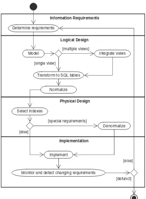
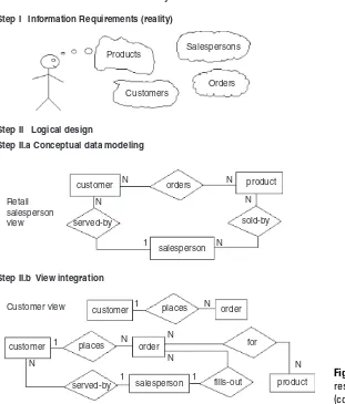
The database life cycle incorporates the basic steps involved in designing a global schema of the logical database, allocating data across a computer network, and defining local DBMS-specific schemas. Once the design is completed, the life cycle continues with database implementation and maintenance. This chapter contains an overview of the data-base life cycle, as shown inFigure 1.1. In succeeding chapters we will focus on the database design process from the modeling of requirements through logical design (Steps I and II below). We illustrate the result of each step of the life cycle with a series of diagrams inFigure 1.2. Each diagram shows a possible form of the output of each step so the reader can see the progression of the design process from an idea to an actual database implementation. These forms are discussed in much more detail in Chapters 2–6.
I. Requirements analysis. The database requirements are determined by interviewing both the producers and users of data and using the information to produce a formal requirements specification. That specification includes the data required for processing, the natural data relationships, and the software platform for the database implementation. As an example,Figure 1.2(Step I) shows the concepts of products, customers, salespersons, and orders being formulated in the mind of the end user dur-ing the interview process.
a. Conceptual data modeling.The data requirements are analyzed and modeled by using an ER or UML dia-gram that includes many features we will study in Chapters 2 and 3, for example, semantics for optional relationships, ternary relationships, supertypes, and subtypes (categories). Processing requirements are typically specified using natural language expressions or SQL commands along with the frequency of occur-rence. Figure 1.2 (Step II.a) shows a possible ER
Information Requirements
Determine requirements
Logical Design
[multiple views]
Model Integrate views
[single view]
Transform to SQL tables
Normalize
Physical Design
Select indexes
[special requirements]
Denormalize [else]
Implementation
Implement
[else]
Monitor and detect changing requirements
[defunct]
model representation of the product/customer data-base in the mind of the end user.
b. View integration.Usually, when the design is large and more than one person is involved in requirements anal-ysis, multiple views of data and relationships occur, resulting in inconsistencies due to variance in taxon-omy, context, or perception. To eliminate redundancy and inconsistency from the model, these views must
Customers
Retail salesperson view
Customer view
Integration of retail salesperson’s and customer’s views customer Step I Information Requirements (reality)
Step II Logical design
Step II.b View integration
Step II.a Conceptual data modeling
salesperson
be “rationalized” and consolidated into a single global view. View integration requires the use of ER semantic tools such as identification of synonyms, aggregation, and generalization. InFigure 1.2(Step II.b), two possi-ble views of the product/customer database are merged into a single global view based on common data for customer and order. View integration is also important when applications have to be integrated, and each may be written with its own view of the database.
Step II.c Transformation of the conceptual data model to SQL tables
Step II.d Normalization of SQL tables
Step III Physical Design
create table customer
Customer
Decomposition of tables and removal of update anomalies.
Salesperson SalesVacations Product
Salesperson sales-name
Order Order-product
order-no sales-name cust-no order-no prod-no addr dept job-level
cust-name ... (cust–no integer, cust–name char(15),
c. Transformation of the conceptual data model to SQL tables. Based on a categorization of data modeling con-structs and a set of mapping rules, each relationship and its associated entities are transformed into a set of DBMS-specific candidate relational tables. We will show these transformations in standard SQL in Chapter 5. Redundant tables are eliminated as part of this pro-cess. In our example, the tables in Step II.c ofFigure 1.2
are the result of transformation of the integrated ER model in Step II.b.
d. Normalization of tables. Given a table (R), a set of attributes (B) is functionally dependent on another set of attributes (A) if, at each instant of time, each A value is associated with exactly one B value. Func-tional dependencies (FDs) are derived from the con-ceptual data model diagram and the semantics of data relationships in the requirements analysis. They represent the dependencies among data elements that are unique identifiers (keys) of entities. Addi-tional FDs, which represent the dependencies between key and nonkey attributes within entities, can be derived from the requirements specification. Candidate relational tables associated with all derived FDs are normalized (i.e., modified by decomposing or splitting tables into smaller tables) using standard normalization techniques. Finally, redundancies in the data that occur in normalized candidate tables are analyzed further for possible elimination, with the constraint that data integrity must be preserved. An example of normalization of the Salesperson table into the new Salesperson and SalesVacations tables is shown in Figure 1.2 from Step II.c to Step II.d.
III.Physical design. The physical design step involves the selection of indexes (access methods), partitioning, and clustering of data. The logical design methodology in Step II simplifies the approach to designing large rela-tional databases by reducing the number of data dependencies that need to be analyzed. This is accom-plished by inserting the conceptual data modeling and integration steps (Steps II.a and II.b of Figure 1.2) into the traditional relational design approach. The objective of these steps is an accurate representation of reality. Data integrity is preserved through normalization of the candidate tables created when the conceptual data model is transformed into a relational model. The pur-pose of physical design is to then optimize performance. As part of the physical design, the global schema can sometimes be refined in limited ways to reflect pro-cessing (query and transaction) requirements if there are obvious large gains to be made in efficiency. This is calleddenormalization. It consists of selecting domi-nant processes on the basis of high frequency, high vol-ume, or explicit priority; defining simple extensions to tables that will improve query performance; evaluating total cost for query, update, and storage; and consider-ing the side effects, such as possible loss of integrity. This is particularly important for online analytical pro-cessing (OLAP) applications.
IV.Database implementation, monitoring, and modifica-tion. Once the design is completed, the database can be created through implementation of the formal schema using the data definition language (DDL) of a DBMS. Then the data manipulation language (DML) can be used to query and update the database, as well as to set up indexes and establish constraints, such as referential integrity. The language SQL contains both DDL and DML con-structs; for example, thecreate tablecommand represents DDL, and theselectcommand represents DML.
user expectations increase with good performance. Thus, the life cycle continues with monitoring, redesign, and modifications. In the next two chapters we look first at the basic data modeling concepts; then, starting in Chapter 4, we apply these concepts to the database design process.
Conceptual Data Modeling
Conceptual data modeling is the driving component of logical database design. Let us take a look of how this important component came about and why it is important. Schema diagrams were formalized in the 1960s by Charles Bachman. He used rectangles to denote record types and directed arrows from one record type to another to denote a one-to-many relationship among instances of records of the two types. The entity-relationship (ER) approach for conceptual data modeling, one of the two approaches emphasized in this book, and described in detail in Chapter 2, was first presented in 1976 by Peter Chen. The Chen form of ER models uses rectangles to specify entities, which are somewhat analogous to records. It also uses diamond-shaped objects to represent the various types of relationships, which are differentiated by numbers or letters placed on the lines connecting the diamonds to the rectangles.
The Unified Modeling Language (UML) was introduced in 1997 by Grady Booch and James Rumbaugh and has become a standard graphical language for specifying and documenting large-scale software systems. The data modeling component of UML (now UML-2) has a great deal of similarity with the ER model, and will be presented in detail in Chapter 3. We will use both the ER model and UML to illustrate the data modeling and logical database design examples throughout this book.
executing queries and updates through the use of DBMS software, and therefore has a vested interest in the data-base design process.
Summary
Knowledge of data modeling and database design tec-hniques is important for database practitioners and appli-cation developers. The database life cycle shows what steps are needed in a methodical approach to designing a database, from logical design, which is independent of the system environment, to physical design, which is based on the details of the database management system chosen to implement the database. Among the variety of data modeling approaches, the ER and UML data models are arguably the most popular in use today because of their simplicity and readability.
Tips and Insights for Database
Professionals
Tip 1. Work methodically through the steps of the life cycle. Each step is clearly defined and has pro-duced a result that can serve as a valid input to the next step.
Tip 2. Correct design errors as soon as possible by going back to the previous step and trying new alternatives. The later you wait, the more costly the errors and the lon-ger the fixes.
Tip 3. Separate the logical and physical design com-pletely because you are trying to satisfy comcom-pletely dif-ferent objectives.
Logical design. The objective is to obtain a feasible solution to satisfy all known and potential queries and updates. There are many possible designs; it is not necessary to find a “best” logical design, just a feasible one. Save the effort for optimization for phys-ical design.
Literature Summary
Much of the early data modeling work was done by Bachman (1969, 1972), Chen (1976), Senko et al. (1973), and others. Database design textbooks that adhere to a sig-nificant portion of the relational database life cycle described in this chapter are Teorey and Fry (1982), Muller (1999), Stephens and Plew (2000), Silverston (2001), Harrington (2002), Bagui (2003), Hernandez and Getz (2003), Simsion and Witt (2004), Powell (2005), Ambler and Sadalage (2006), Scamell and Umanath (2007), Halpin and Morgan (2008), Mannino (2008), Stephens (2008), Churcher (2009), and Hoberman (2009).
2
THE ENTITY–RELATIONSHIP
MODEL
CHAPTER OUTLINE
Fundamental ER Constructs 15
Basic Objects: Entities, Relationships, Attributes 15
Degree of a Relationship 19
Connectivity of a Relationship 20
Attributes of a Relationship 21
Existence of an Entity in a Relationship 22
Alternative Conceptual Data Modeling Notations 23
Advanced ER Constructs 23
Generalization: Supertypes and Subtypes 23
Aggregation 27
Ternary Relationships 28
General n-ary Relationships 31
Exclusion Constraint 31
Foreign Keys and Referential Integrity 32
Summary 32
Tips and Insights for Database Professionals 33
Literature Summary 34
This chapter defines all the major entity–relationship (ER) concepts that can be applied to the conceptual data modeling phase of the database life cycle.
The ER model has two levels of definition—one that is quite simple and another that is considerably more com-plex. The simple level is the one used by most current design tools. It is quite helpful to the database designer who must communicate with end users about their data requirements. At this level you simply describe, in diagram
form, the entities, attributes, and relationships that occur in the system to be conceptualized, using semantics that are definable in a data dictionary. Specialized constructs, such as “weak” entities or mandatory/optional existence notation, are also usually included in the simple form. But very little else is included, in order to avoid cluttering up the ER diagram while the designer’s and end user’s understandings of the model are being reconciled.
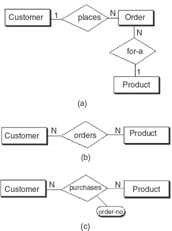
An example of a simple form of ER model using the Chen notation is shown in Figure 2.1. In this example we want to keep track of videotapes and customers in a video store. Videos and customers are represented as entities Video and Customer, and the relationship “rents” shows a many-to-many association between them. Both Video and Customer entities have a few attributes that describe their characteristics, and the relationship “rents” has an attribute due date that represents the date that a particular video rented by a specific customer must be returned.
From the database practitioner’s standpoint, the simple form of the ER model (or UML) is the preferred form for both data modeling and end user verification. It is easy to learn and applicable to a wide variety of design problems that might be encountered in industry and small businesses. As we will demonstrate, the simple form is easily translatable into SQL data definitions, and thus it has an immediate use as an aid for database implementation.
The complex level of ER model definition includes con-cepts that go well beyond the simple model. It includes concepts from the semantic models of artificial intelli-gence and from competing conceptual data models. Data modeling at this level helps the database designer capture more semantics without having to resort to narrative explanations. It is also useful to the database application
Customer N rents N
due-date cust-id
cust-name
video-id
copy-no
title Video
programmer, because certain integrity constraints defined in the ER model relate directly to code—code that checks range limits on data values and null values, for example. However, such detail in very large data model diagrams actually detracts from end user understanding. Therefore, the simple level is recommended as the basic communica-tion tool for database design verificacommunica-tion.
In the next section, we will look at the simple level of ER modeling described in the original work by Chen and extended by others. The following section presents the more advanced concepts that are less generally accepted but useful to describe certain semantics that cannot be constructed with the simple model.
Fundamental ER Constructs
Basic Objects: Entities, Relationships, Attributes
The basic ER model consists of three classes of objects: entities, relationships, and attributes.Entities
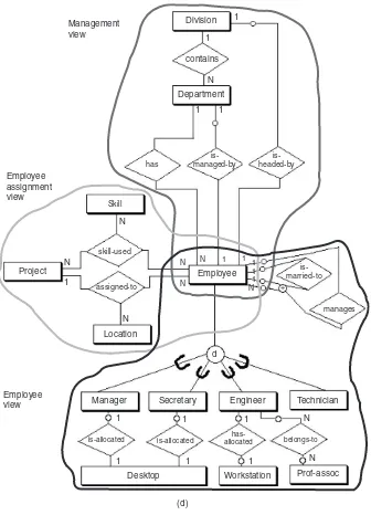
Entitiesare the principal data objects about which infor-mation is to be collected; they usually denote a person, place, thing, or event of informational interest. A particular occurrence of an entity is called an entity instance, or sometimes anentity occurrence. In our example, Employee, Department, Division, Project, Skill, and Location are all examples of entities (for easy reference, entity names will be capitalized throughout this text). The entity construct is a rectangle as depicted in Figure 2.2. The entity name is written inside the rectangle.
Relationships
Relationships represent real-world associations among
connectivity between entity occurrences: to-one, one-to-many, and many-to-many. The relationship construct is a diamond that connects the associated entities, as shown in
Figure 2.2. The relationship name can be written inside or just outside the diamond.
Aroleis the name of one end of a relationship when each end needs a distinct name for clarity of the relationship. In most of the examples given inFigure 2.3, role names are not required because the entity names combined with the relationship name clearly define the individual roles of each entity in the relationship. However, in some cases role names should be used to clarify ambiguities. For example, in the first case inFigure 2.3, the recursive binary relation-ship “manages” uses two roles, “manager” and “subordi-nate,” to associate the proper connectivities with the two different roles of the single entity. Role names are typically nouns. In this diagram one role of an employee is to be the “manager” of up tonother employees. The other role is for a particular “subordinate” to be managed by exactly one other employee.
Concept Representation & Example
Entity
Weak entity
Relationship
Attribute identifier (key)
descriptor (nonkey)
multivalued descriptor
complex attribute
Employee
works-in
emp-id
emp-name
degrees
street city state
zip-code
address Employee-job-history
Employee
Concept Representation & Example
Attributes and Keys
Attributes are characteristics of entities that provide descriptive detail about them. A particular instance (or occurrence) of an attribute within an entity or relationship is called anattribute value. Attributes of an entity such as Employee may include emp-id, emp-name, emp-address, phone-no, fax-no, job-title, and so on. The attribute con-struct is an ellipse with the attribute name inside (or oblong as shown inFigure 2.2). The attribute is connected to the entity it characterizes.
There are two types of attributes: identifiers and descriptors. Anidentifier(or key) is used to uniquely determine an instance of an entity. For example, an identifier or key of Employee is emp-id; each instance of Employee has a different value for emp-id, and thus there are no duplicates of emp-id in the set of Employees. Key attributes are underlined in the ER diagram, as shown in Figure 2.2. We note, briefly, that you can have more than one identifier (key) for an entity, or you can have a set of attributes that compose a key (see the “Super-keys, Candidate Keys, and Primary Keys” section in Chapter 6). Adescriptor(or nonkey attribute) is used to specify a non-unique characteristic of a particular entity instance. For example, a descriptor of Employee might be emp-name or job-title; different instances of Employee may have the same value for emp-name (two John Smiths) or job-title (many Senior Programmers).
Both identifiers and descriptors may consist of either a single attribute or some composite of attributes. Some attributes, such as specialty-area, may be multivalued. The notation for multivalued attributes is shown with a double attachment line, as shown in Figure 2.2. Other attributes may be complex, such as an address that further subdivides into street, city, state, and zip code.
Weak Entities
Entities have internal identifiers or keys that uniquely determine each entity occurrence, but weak entities are entities that derive their identity from the key of a connected “parent” entity. Weak entities are often depicted with a dou-ble-bordered rectangle (seeFigure 2.2), which denotes that all instances (occurrences) of that entity are dependent for their existence in the database on an associated entity. For example, inFigure 2.2, the weak entity his-tory is related to the entity Employee. The Employee-job-history for a particular employee only can exist if there exists an Employee entity for that employee.
Degree of a Relationship
The degree of a relationship is the number of entities associated in the relationship. Binary and ternary relationships are special cases where the degree is 2 and 3, respectively. An n-ary relationship is the general form for any degree n. The notation for degree is illustrated in
Figure 2.3. The binary relationship, an association between two entities, is by far the most common type in the natural world. In fact, many modeling systems use only this type. In Figure 2.3 we see many examples of the association of two entities in different ways: Department and Division, Department and Employee, Employee and Project, and so on. A binary recursive relationship (e.g., “manages” in
Figure 2.3) relates a particular Employee to another Employee by management. It is called recursive because the entity relates only to another instance of its own type. The binary recursive relationship construct is a diamond with both connections to the same entity.
achieve both simplicity and semantic purity. Ternary relationships are discussed in greater detail in the “Ternary Relationships” section below and in Chapter 5.
An entity may be involved in any number of relationships, and each relationship may be of any degree. Furthermore, two entities may have any number of binary relationships between them, and so on for any n entities (see n-ary relationships defined in the “General n-ary Relationships” section below).
Connectivity of a Relationship
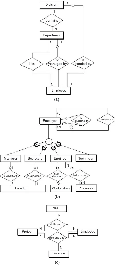
Theconnectivity of a relationship describes a constraint on the connection of the associated entity occurrences in the relationship. Values for connectivity are either “one” or “many.” For a relationship between entities Department and Employee, a connectivity of one for Department and many for Employee means that there is at most one entity occurrence of Department associated with many occurrences of Employee. The actual count of elements associated with the connectivity is called the cardinality of the relationship connectivity; it is used much less fre-quently than the connectivity constraint because the actual values are usually variable across instances of relationships. Note that there are no standard terms for the connectivity concept, so the reader is admonished to look at the definition of these terms carefully when using a particular database design methodology.
Figure 2.3 shows the basic constructs for connectivity for binary relationships: one-to-one, one-to-many, and many-to-many. On the “one” side, the number 1 is shown on the connection between the relationship and one of the entities, and on the “many” side, the letter N is used on the connection between the relationship and the entity to designate the concept of many.
In the one-to-one case, the entity Department is man-aged by exactly one Employee, and each Employee manages exactly one Department. Therefore, the minimum and max-imum connectivities on the “is-managed-by” relationship are exactly one for both Department and Employee.
connectivity is given on the Employee (many) side as the unknown value N, but the minimum connectivity is known as one. On the Department side the minimum and maxi-mum connectivities are both one—that is, each Employee works within exactly one Department.
In the many-to-many case, a particular Employee may work on many Projects and each Project may have many Employees. We see that the maximum connectivity for Employee and Project is N in both directions, and the minimum connectivities are each defined (implied) as one.
Some situations, though rare, are such that the actual maximum connectivity is known. For example, a profes-sional basketball team may be limited by conference rules to 12 players. In such a case, the number 12 could be placed next to an entity called Team Members on the many side of a relationship with an entity Team. Most situations, however, have variable connectivity on the many side, as shown in all the examples ofFigure 2.3.
Attributes of a Relationship
Attributes can be assigned to certain types of relationships as well as to entities. An attribute of a many-to-many relation-ship such as the “works-on” relationrelation-ship between the entities Employee and Project (Figure 2.3) could be “task-assign-ment” or “start-date.” In this case, a given task assignment or start date only has meaning when it is common to an instance of the assignment of a particular Employee to a par-ticular Project via the relationship “works-on.”
that an employee can manage many departments over time, then the attribute start-date must shift to the rela-tionship so each instance of the relarela-tionship that matches one employee with one department can have a unique start date for that employee as the manager of that department.
Existence of an Entity in a Relationship
Existence of an entity occurrence in a relationship is defined as either mandatory or optional. If an occurrence of either the “one” or “many” side entity must always exist for the entity to be included in the relationship, then it is mandatory. When an occurrence of that entity need not always exist, it is considered optional. For example, in
Figure 2.3 the entity Employee may or may not be the manager of any Department, thus making the entity Department in the “is-managed-by” relationship between Employee and Department optional.
Optional existence, defined by a 0 on the connection line between an entity and a relationship, defines a minimum connectivity of zero. Mandatory existence defines a mini-mum connectivity of one. When existence is unknown, we assume the minimum connectivity is one—that is, mandatory.
Maximum connectivities are defined explicitly on the ER diagram as a constant (if a number is shown on the ER diagram next to an entity) or a variable (by default if no number is shown on the ER diagram next to an entity). For example, in Figure 2.3 the relationship “is-occupied-by” between the entity Office and Employee implies that an Office may house from zero to some var-iable maximum (N) number of Employees, but an Employee must be housed in exactly one Office—that is, it is mandatory.
Alternative Conceptual Data Modeling Notations
At this point we need to digress briefly to look at other conceptual data modeling notations that are commonly used today and compare them with the Chen approach. A popular alternative form for one-to-many and many-to-many relationships uses “crow’s foot” notation for the “many” side (see Figure 2.4a). This form was used by some CASE tools, such as KnowledgeWare’s Information Engineering Workbench (IEW). Relationships have no explicit construct but are implied by the connection line between entities and a relationship name on the connec-tion line. Minimum connectivity is specified by either a 0 (for zero) or perpendicular line (for one) on the connec-tion lines between entities. The term intersection entity is used to designate a weak entity, especially an entity that is equivalent to a many-to-many relationship. Another popular form used today is the IDEF1X notation (IDEF1X, 2005), conceived by Robert G. Brown (Bruce, 1992). The similarities with the Chen notation are obvious fromFigure 2.4(b). Fortunately, any of these forms is reasonably easy to learn and read, and their equivalence for the basic ER concepts is obvious from the diagrams. Without a clear standard for the ER model, however, many other constructs are being used today in addition to the three types shown here.
Advanced ER Constructs
Generalization: Supertypes and Subtypes
ER model constructs
weak entity intersection entity
is-group-leader-of
ER model constructs using the “crow’s foot” approach
[Knowledgeware]
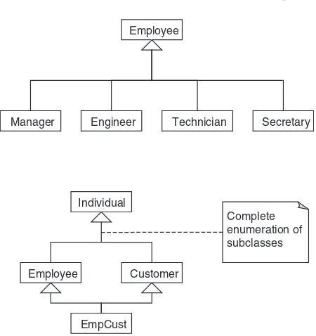
entities—subtypes in a generalization hierarchy—can be either disjoint or overlapping subsets of the supertype entity. As an example, inFigure 2.5the entity Employee is a higher-level abstraction of Manager, Engineer, Techni-cian, and Secretary, all of which are disjoint types of Employee. The ER model construct for the generalization abstraction is the connection of a supertype entity with its subtypes, using a circle and the subset symbol on the connecting lines from the circle to the subtype entities. The circle contains a letter specifying a disjointness con-straint (see the following discussion). Specialization, the reverse of generalization, is an inversion of the same con-cept; it indicates that subtypes specialize the supertype.
A supertype entity in one relationship may be a subtype entity in another relationship. When a structure comprises a combination of supertype/subtype relationships, that structure is called asupertype/subtype hierarchy, or generali-zation hierarchy. Generalization can also be described in terms of inheritance, which specifies that all the attributes of a supertype are propagated down the hierarchy to entities of a lower type. Generalization may occur when a generic
Manager Engineer Technician
supertype
subtypes
(a)
(b) Employee
Employee Customer o
Individual d
Secretary
entity, which we call the supertype entity, is partitioned by different values of a common attribute. For example, in
Figure 2.5, the entity Employee is a generalization of Manager, Engineer, Technician, and Secretary over the attribute job-title in Employee.
Generalization can be further classified by two important constraints on the subtype entities: disjointness and com-pleteness. The disjointness constraint requires the subtype entities to be mutually exclusive. We denote this type of con-straint by the letter “d” written inside the generalization cir-cle (Figure 2.5a). Subtypes that are not disjoint (i.e., that overlap) are designated by using the letter “o” inside the cir-cle. As an example, the supertype entity Individual has two subtype entities, Employee and Customer; these subtypes could be described as overlapping or not mutually exclusive (Figure 2.5b). Regardless of whether the subtypes are dis-joint or overlapping, they may have additional special attributes in addition to the generic (inherited) attributes from the supertype.
The completeness constraint requires the subtypes to be all-inclusive of the supertype. Thus, subtypes can be defined as either total or partial coverage of the supertype. For example, in a generalization hierarchy with supertype Individual and subtypes Employee and Customer, the subtypes may be described as all-inclusive or total. We denote this type of constraint by a double line between the supertype entity and the circle. This is indicated in
Figure 2.5(b), which implies that the only types of individuals to be considered in the database are employees and customers.
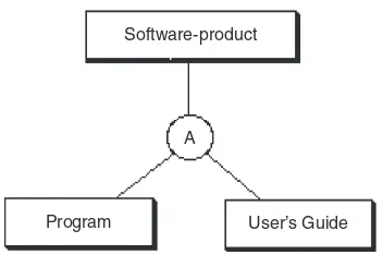
Aggregation
in Figure 2.6 the entity Software-product is seen to consist of component parts Program and User’s Guide. The construct for aggrega-tion is similar to generalizaaggrega-tion in that the supertype entity is connected with the sub-type entities with a circle; in this case, the let-ter A is shown in the circle. However, there are no subset symbols because the “part-of” relationship is not a subset. Furthermore, there are no inherited attributes in aggrega-tion; each entity has its own unique set of attributes.
Ternary Relationships
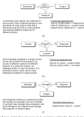
Ternary relationships are required when binary relationships are not sufficient to accurately describe the semantics of an association among three entities. Ternary relationships are somewhat more complex than binary relationships, however. The ER notation for a ternary rela-tionship is shown inFigure 2.7with three entities attached to a single relationship diamond, and the connectivity of each entity is designated as either “one” or “many.” An entity in a ternary relationship is considered to be “one” if only one instance of it can be associated with one instance of each of the other two associated entities. It is “many” if more than one instance of it can be associated with one instance of each of the other two associated entities. In either case, it is assumed that one instance of each of the other entities is given.
As an example, the relationship “manages” inFigure 2.7(c)
associates the entities Manager, Engineer, and Project. The entities Engineer and Project are considered “many”; the entity Manager is considered “one.” This is represented by the following assertions:
Assertion 1: One engineer, working under one manager,
could be working on many projects.
Assertion 2: One project, under the direction of one
manager, could have many engineers.
Assertion 3:One engineer, working on one project, must have only a single manager.
Software-product
Program User’s Guide A
Project Project
Each employee assigned to a project works at only one location for that project, but can be at different locations for different projects. At a particular location, an employee works on only one project. At a particular location, there can be many employees assigned to a given project.
assigned-to
Employee
Functional dependencies Location
emp-id, loc-name -> project-name emp-id, project-name -> loc-name
Engineer
Each engineer working on a particular project has exactly one manager, but each manager of a project may manage many engineers, and each manager of an engineer may manage that engineer on many projects.
(c) (b) (a)
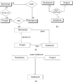
project-name, emp-id -> mgr-id Functional dependency Technician notebookuses- Project
Functional dependencies Notebook
1
1 1
A technician uses exactly one notebook for each project. Each notebook belongs to one technician for each project. Note that a technician may still work on many projects and maintain different notebooks for different projects.
emp-id, project-name -> notebook-no emp-id, notebook-no -> project-name project-name, notebook-no -> emp-id
Figure 2.7 Ternary relationships: (a) one-to-one-to-one ternary relationship, (b) one-to-one-to-many ternary relationship, (c) one-to-many-to-many ternary relationship, and
Assertion 3 could also be written in another form, using an arrow (->) in a kind of shorthand called a functional dependency. For example:
emp-id, project-name ->mgr-id
where emp-id is the key (unique identifier) associated with the entity Engineer, project-name is the key associated with the entity Project, and mgr-id is the key of the entity Manager. In general, for an n-ary relationship, each entity considered to be a “one” has its key appearing on the right side of exactly one functional dependency (FD). No entity considered “many” ever has its key appear on the right side of an FD.
All four forms of ternary relationships are illustrated in
Figure 2.7. In each case the number of “one” entities implies the number of FDs used to define the relationship semantics, and the key of each “one” entity appears on the right side of exactly one FD for that relationship.
Ternary relationships can have attributes in the same way as many-to-many binary relationships can. The values of these attributes are uniquely determined by some combina-tion of the keys of the entities associated with the relacombina-tion- relation-ship. For example, in Figure 2.7(d) the relationship “skill-used” might have the attribute “tool” associated with a given employee using a particular skill on a certain project, indicating that a value for tool is uniquely determined by the combination of employee, skill, and project.
Employee N N Project
Skill skill-used
Functional dependencies None
N
Employees can use many skills on any one of many projects, and each project has many employees with various skills.
(d)
General
n
-ary Relationships
Generalizing the ternary form to higher-degree relationships, an n-ary relationship that describes some associa-tion among n entities is represented by a single relationship diamond with n connections, one to each entity (Figure 2.8). The meaning of this form can best be described in terms of thefunc-tional dependencies among the keys of the n associated entities. There can be anywhere from zero to n FDs, depending on the number of “one” entities. The collection of FDs that describe an n-ary relationship must each have n components:n 1 on the left side (determinant) and 1 on the right side. A ternary relationship (n ¼ 3), for example,
has two components on the left and one on the right, as we saw in the example inFigure 2.7. In a more complex database, other types of FDs may also exist within ann-ary relationship. When this occurs, the ER model does not provide enough semantics by itself, and it must be supplemented with a narra-tive description of these dependencies.
Exclusion Constraint
The normal, or default, treatment of multiple relation-ships is the inclusive OR, which allows any or all of the entities to participate. In some situations, however, multiple relationships may be affected by the exclusive OR (exclu-sion) constraint, which allows at most one entity instance among several entity types to participate in the relationship with a single root entity. For example, inFigure 2.9suppose the root entity Work-task has two associated entities,
Student enrolls-in
Day
Room Time
Class
Figure 2.8 n-ary relationships.
Work-task
A work task can be assigned to either an external project or an internal project, but not both.
is-for
Internal-project Figure 2.9 Exclusion
External-project and Internal-project. At most, one of the associated entity instances could apply to an instance of Work-task.
Foreign Keys and Referential Integrity
A foreign key is an attribute of an entity or an equiva-lent SQL table, which may be either an identifier or a descriptor. A foreign key in one entity (or table) is taken from the same domain of values as the (primary) key in another (parent) table in order for the two tables to be connected to satisfy certain queries on the database.
Ref-erential integrity requires that for every foreign key
instance that exists in a table, the row (and thus the key instance) of the parent table associated with that for-eign key instance must also exist. The referential integ-rity constraint has become integral to relational database design and is usually implied as a requirement for the resulting relational database implementation. (Chapter 5 illustrates the SQL implementation of refer-ential integrity constraints.)
Summary
The basic concepts of the ER model and their constructs are described in this chapter. An entity is a person, place, thing, or event of informational interest. Attributes are objects that provide descriptive information about entities. Attributes may be unique identifiers or nonunique descriptors. Relationships describe the connectivity between entity instances: one-to-one, one-to-many, or many-to-many. The degree of a relationship is the number of associated entities: two (binary), three (ternary), or any n (n-ary). The role (name), or relationship name, defines the function of an entity in a relationship.
The concept of existence in a relationship determines whether an entity instance must exist (mandatory) or not (optional). So, for example, the minimum connectivity of a binary relationship—that is, the number of entity instances on one side that are associated with one instance on the other side—can either be zero, if
generalization allows for the implementation of super-type and subsuper-type abstractions.
This simple form of ER models is used in most design tools and is easy to learn and apply to a variety of indus-trial and business applications. It is also a very useful tool for communicating with the end user about the conceptual model and for verifying the assumptions made in the modeling process.
A more complex form, a superset of the simple form, is useful for the more experienced designer who wants to capture greater semantic detail in diagram form, while avoiding having to write long and tedious narrative to explain certain requirements and constraints. The more advanced constructs in ER diagrams are sporadically used and have no generally accepted form as yet. They include ternary relationships, which we define in terms of the FD concept of relational databases; constraints on exclusion; and the implicit constraints from the relational model such as referential integrity.
Tips and Insights for Database
Professionals
Tip 1. ER is a much better level of abstraction than
specifying individual data items or functional
dependencies, and it is easier to use to develop a con-ceptual model for large databases. The main advantages of ER modeling are that it is easy to learn, easy to use, and very easy to transform to SQL table definitions.
Tip 2. Identify entities first, then relationships, and finally the attributes of entities.
Tip 3. Identify binary relationships first whenever pos-sible. Only use ternary relationships as a last resort. Tip 4. ER model notations are all very similar.Pick the notation that works best for you unless your client or boss prefers a specific notation for their purposes. Remember that ER notation is the primary tool for com-municating data concepts with your client.
Tip 5. Keep the ER model simple. Too much detail
Literature Summary
3
THE UNIFIED MODELING
LANGUAGE
CHAPTER OUTLINE
Class Diagrams 36
Basic Class Diagram Notation 37
Class Diagrams for Database Design 39
Example from the Music Industry 44
Activity Diagrams 47
Activity Diagram Notation Description 48
Activity Diagrams for Workflow 50
Summary 52
Tips and Insights for Database Professionals 52
Literature Summary 53
The Unified Modeling Language (UML) is a graphical language for communicating design specifications for soft-ware. The object-oriented software development commu-nity created UML to meet the special needs of describing object-oriented software design. UML has grown into a standard for the design of digital systems in general.
There are a number of different types of UML diagrams serving various purposes (Rumbaugh et al., 2005). Theclass and the activity diagram types are particularly useful for discussing database design issues. UML class diagrams capture the structural aspects found in database schemas. UML activity diagrams facilitate discussion on the dynamic processes involved in database design. This chapter is an overview of the syntax and semantics of the UML class and activity diagram constructs used in this book. These same concepts are useful for planning, documenting, discussing,
and implementing databases. We are using UML 2.0, although for the purposes of the class diagrams and activity diagrams shown in this book, if you are familiar with UML 1.4 or 1.5 you will probably not see any differences.
UML class diagrams and entity–relationship (ER) models (Chen, 1976; Chen, 1987) are similar in both form and semantics. The original creators of UML point out the influence of ER models on the origins of class diagrams (Rumbaugh et al., 2005). The influence of UML has in turn affected the database community. Class diagrams now appear frequently in the database literature to describe database schemas.
UML activity diagrams are similar in purpose to flow charts. Processes are partitioned into constituent activities along with control flow specifications.
This chapter is organized into three main sections. The first section presents class diagram notation, along with examples. The next section covers activity diagram nota-tion, along with illustrative examples. Finally, the last sec-tion concludes with a few tips for UML usage.
Class Diagrams
A class is a descriptor for a set of objectsthat share some attributes and/or operations. We conceptualize classes of objects in our everyday lives. For example, a car has attri-butes, such as a vehicle identification number (VIN) and mileage. A car also has operations, such as accelerate and brake. All cars have these attributes and operations. Indivi-dual cars differ in the details. A given car has a value for the VIN and mileage. For example, a given car might have a VIN of 1NXBR32ES3Z126369 with a mileage of 22,137 miles. Individual cars are objects that are instances of the Car class. Classes and objects are a natural way of conceptualizing the world around us. The concepts of classes and objects are also the paradigms that form the foundation of object-oriented programming. The development of object-object-oriented programming led to the need for a language to describe object-oriented design, giving rise to UML.
Database schemas can be diagrammed using UML. It is possible to conceptualize a database table as a class. The columns in the table are the attributes, and the rows are objects of that class. For example, we could have a table namedCarwith columns named “vin” and “mileage” (note that we put table names in boldface throughout the book for readability). Each row in the table would have values for these columns, representing an individual car. A given car might be represented by a row with the value 1NXBR32ES3Z126369 in the vin column, and 22,137 in the mileage column.
The major difference between classes and entities is the lack of operations in entities. Note that the termoperation is used here in the UML sense of the word. Stored pro-cedures, functions, triggers, and constraints are forms of named behavior that can be defined in databases; however, these are not associated with the behavior of individual rows. The term operations in UML refers to the methods inherent in classes of objects. These behaviors are not stored in the definition of rows within the database. There are no operations named “accelerate” or “brake” associated with rows in our Car table in Figure 3.1. Classes can be shown with attributes and no operations in UML, which is the typical usage for database schemas.
Basic Class Diagram Notation
The class notation has some variations, reflecting empha-sis. Classes can be written without the attribute com-partment and/or the operations comcom-partment. Operations are important in software. If the software designer wishes to focus on the operations, the class can be shown with only the class name and operations compartments. Showing operations and hiding attributes is a very common syntax used by software designers. Database designers, on the other hand, do not generally deal with class operations; however, the attributes are of paramount importance. The needs of the database designer can be met by writing the class with only the class name and attribute compartments showing. Hiding operations and showing attributes is an uncommon syntax for a software designer, but it is common for database
Class Name
design. Lastly, in high-level diagrams, it is often desirable to illustrate the relationships of the classes without becoming entangled in the details of the attributes and operations. Classes can be written with just the class name compart-ment when simplicity is desired.
Various types of relationships may exist between clas-ses. Associations are one type of relationship. The most generic form of association is drawn with a line connecting two classes. For example, inFigure 3.1there is an associa-tion between the Car class and the Driver class.
A few types of associations, such as aggregation and
composition, are very common. UML has designated
symbols for these associations. Aggregation indicates “part of” associations, where the parts have an independent existence. For example, a Car may be part of a Car Pool. The Car also exists on its own, independent of any Car Pool. Another distinguishing feature of aggregation is that the part may be shared among multiple objects. For exam-ple, a Car may belong to more than one Car Pool. The aggregation association is indicated with a hollow diamond attached to the class that holds the parts.Figure 3.1 indi-cates that a Car Pool aggregates Cars.
Composition is another “part of” association, where the parts are strictly owned, not shared. For example, a Frame is part of a single Car. The notation for composition is an association adorned with a solid black diamond attached to the class that owns the parts. Figure 3.1 indicates that a Frame is part of the composition of a Car.
Generalization is another common relationship. For example, Sedan is a type of car. The Car class is more general than the Sedan class. Generalization is indicated by a solid line adorned with a hollow arrowhead pointing to the more general class. Figure 3.1 shows generalization from the Sedan class to the Car class.
Class Diagrams for Database Design
The reader may be interested in the similarities and differences between UML class diagrams and ER models.
Figure 3.6. We conclude this section with an example database schema of the music industry, illustrated by
Figures 3.7 through 3.10.
Figure 3.2 illustrates UML constructs for relationships with various degrees of association and multiplicities. These examples are parallel to the ER models shown in Figure 2.3. You may refer back to Figure 2.3 if you wish to contrast the UML constructs with ER constructs.
Associations between classes may be reflexive, binary, or n-ary. Reflexive association is a term we are carrying over from ER modeling. It is not a term defined in UML, although it is worth discussing. Reflexive association
Employee
managed manager 1
*
Department * 1 Division
Skill skill used Project
*