PLC-based process controller is a process control system which has the base of SYSMAC SC/CJ series. It can be adopted for both loop control which controls analog signals and sequence control which mainly handles contacts.
By combining a loop controller and process I/O units, loop control functionality can be added onto the PLC, maintaining the basic PLC function.When developing a system, operating environment, such as initial setting of PLC is required, so that the PLC can operate.
Then, utilize CX-Process, the tool software of loop controller to build the system. HMI can be se-lected from the Touch panel (NS series), special monitoring software CX-Process Monitor Plus, and general HMI software, depending on the application.
About this Manual
This manual describes the procedure to build a PLC-based Process Control system and includes the sections below.
Section1 outlines the features and mechanism of the Loop Controllers
Section2 describes the procedure to build an example system on the Loop Controller.
Section3 provides the names and functions of parts, and provides other information required toin-stall and operate Loop Controllers.
Section 4 describes application cases of PLC-based Process Control system.
The CS-series CS1W-LCB01 and CS1W-LCB05 Loop Control Boards, CS1D-CPU**P Process-control CPU Units, and CJ1G-CPU**P Loop-Process-control CPU Units help you build an instrumentation system comprising multiple loops. A Loop Control Board is installed as an Inner Board in the CPU Unit of a CS-series PLC (Programmable Controller).
The CS1W-LCB01 and CS1W-LCB05 Loop Control Boards must be installed in CS1-H CPU Units.They cannot be used in CS1 CPU Units.
Please read this manual and the other manuals related to the CS1W-LCB01 and CS1W-LCB05 Loop Control Boards, CS1D-CPU**P Process-control CPU Units, and CJ1G-CPU**P Loop-control CPU Units carefully and be sure you understand the information provided before attempting to in-stall and operate the products. The manuals used with the CS1W-LCB01 and CS1W-LCB05 Loop Control Boards, CS1D-CPU**P Process-control CPU Units, and CJ1G-CPU**P Loop-control CPU Units are listed in the following table. The suffixes have been omitted from the catalog numbers. Be sure you are using the most recent version for your area.
When using CS1D Process-control CPU Units, refer to the following manuals for information on theCS1D CPU Unit elements.
Name Contents Cat. No.(suffixes
omitted) PLC-based Process Control Engineering
Guide (This manual)
Describes the procedure to build a PLC-based Process Control system.
W468
SYSMAC CS/CJ SeriesCS1W-LCB01, CS1W-LCB05, CS1D-CPU**P, and CJ1G-CPU**P Operation Manuals
Describes the basic running of the Loop Con-trol Boards (excluding detailed descriptions of the function blocks).
W406
SYSMAC CS/CJ SeriesCS1W-LCB01, CS1W-LCB05,CS1DCPU**P, and CJ1G-CPU**P Function Block Reference Man-ual
Provides detailed information on the function blocks.
W407
CXONE-AL**C-ECX-One FA Integrated Tool Package Setup Manual
Provides an overview of the CX-One FA Inte-grated Tool and installation procedures.
W444
SYSMAC CS/CJ SeriesCX-Process ToolOperation Manual
Describes operation of the CX-Process Tool. W372
Faceplate Auto-Builder for NSOperation Manual
Describes operation of the software that gen-erates NS-series PT projects from a CSV file output by the CX-Process Tool.
W418
Name Contents Cat. No.(suffixes
omitted)
Name Contents Cat. No.(suffix-es omitted) SYSMAC CJ SeriesProgrammable
Con-trollers Operation ManualCJ1G/H-CPU**H, CJ1G-CPU**P,CJ1M-CPU**,CJ1G-CPU**
Provides an outlines of and describes the de-sign, installation, maintenance, and otherbasic operations for the CJ-series PLCs.
W393
SYSMAC CS/CJ SeriesProgrammable ControllersProgramming ManualCS1G/ H-CPU**-EV1,
CS1G/H-CPU**H,CS1DCPU**H, CS1D-CPU**S,CJ1G/H-CPU**H, CJ1G-CPU**P,CJ1M-CPU**, CJ1G-CPU**
This manual describes programming andother methods to use the functions of theCS/CJ-se-ries PLCs.
W394
SYSMAC CS/CJ SeriesProgrammable ControllersInstructions Reference ManualCPU**-EV1, CS1G/H-CPU**H,CS1DCPU**H, CS1D-CPU**S,CJ1G/H-CPU**H, CJ1G-CPU**P,CJ1M-CPU**, CJ1G-CPU**
This manual describes programming andother methods to use the functions of theCS/CJ-se-ries PLCs.
W340
About Loop Controllers
Loop Control Types, Functional Elements, and Versions
Loop Controller Types
There are two types of Loop Controller: Separate Loop Controllers and Loop Controllers Pre-in-stalled in CPU Units.
Loop Controller Function Elements
Separate Loop Controllers consist of only the Loop Controller functional element (i.e., the Loop Controller element).
CPU Units with Pre-installed Loop Controller consist of a CPU Unit functional element (i.e., the CPU Unit element) and the Loop Controller functional element (i.e., the Loop Controller ele-ment).
Versions
The functional elements (i.e., the CPU Unit element and Loop Controller element) have ver-sions.
Human-Machine Interface Recommended by Omron
Notation in this manual
This manual uses the following notation.
"Loop Controller" is used as a generic term to refer to the Loop Controllers in general.
"LCB**" is used to refer to specific Loop Controller functional elements. For example, the Loop Controller function element in a CS1W-LCB05 Loop Controller Board is the LCB05, so "LCB05" is used to refer to the Loop Controller functional element.
EX.) "LCB05 functional elements" is used to refer to Loop Controller functional element of "CS1W-LCB05". "LCB03 functional elements" is used to refer to Loop Controller functional element of Loop CPU Unit CJ1G-CPU44P, because the Loop Controller elements pre-installed in the CPU is LCB03.
Model numbers are used to refer to specific Loop Controller models. Loop Controller
Type
Type name Product name Model PLC series and Unit type
Separate Separate Loop Loop Control Unit CS1W-LC001 CS-series CPU Bus Unit Loop Con-troller
Controller Loop Control Board
CS1W-LCB** CS-series Inner Board Loop Con-troller
Pre-installed in CPU Unit
CPU Unit with Pre-installed Loop Controller
Process-control CPU Unit
CS1D-CPU**P A one-Unit Loop Controller consist-ing of an Inner Board Pre-installed in a CS-series CS1D-H CPU Unit
Loop-control CPU Unit
CJ1G-CPU**P A one-Unit Loop Controller consist-ing of an Inner Board pre-installed in a CJ-series CJ1-H CPU Unit.
Human-machine interface Recommended Software/ Device
HMI Software Omron, CX-Process Monitor Plus
for the purposes described in this manual.The following conventions are used to indicate and classify precau-tions in this manual. Always heed the information provided with them. Failure to heed precauprecau-tions can result in injury to people or damage to property.
OMRON Product Reference
All OMRON products are capitalized in this manual. The work "Unit" is also capitalized when it refers to an OMRON product, regardless of whether or not it appears in the proper name of the product.
The abbreviation "Ch" which appears in some displays and on some OMRON products, often means "word" and is abbreviated "Wd" in documentation in this sense.
The abbreviation "PLC" means Programmable Controller. "PC" is used, however, in some Programming De-vice displays to mean Programmable Controller.
Visual Aids
The following headings appear in the left column of the manual to help you locate different types of informa-tion.
Indicates information of particular interest for efficient and convenient operation of the product.
1, 2,3···
1 indicates lists of one sort or another, such as procedures, checklists, etc.
OMRON, 2007
All rights reserved. No part of this publication may be reproduced, stored in a retrieval system, or transmitted, in any form, or by any means, mechanical, electronic, photocopying, recording, or otherwise, without the prior written permission of OMRON.
No patent liability is assumed with respect to the use of the information contained herein. Moreover, because OMRON is constantly striving to improve its high-quality products, the information contained in this manual is subject to change without notice. Every precaution has been taken in the preparation of this manual. Never-theless, OMRON assumes no responsibility for errors or omissions. Neither is any liability assumed for dam-ages resulting from the user of the information contained in this publication.
Indicates an imminently hazardous situation which, if not avoided, could result in death or serious injury. Additionally, there may be severe property damage.
Read and Understand this Manual
Please read and understand this manual before using the product. Please consult your OMRON representative if you have any questions or comments.
Warranty and Limitations of Liability
WARRANTRY
OMRON's exclusive warranty is that the products are free from defects in materials and workmanship for a period of one year (or other period if specified) from date of sale by OMRON
OMRON MAKES NO WARRANTRY OR REPRESENTATION, EXPRESS OR IMPLIED, REGARDING NONINFRINGEMENT, MERCHANTABILITY, OR FITNESS FOR PARTICULAR PURPOSE OF THE PRODUCTS. ANY BUYER OR USER ACKNOWLEDGES THAT THE BUYER OR USER ALONE HAS DETERMINED THAT THE PRODUCTS WILL SUITABLY MEET THE REQUIREMENTS OF THEIR IN-TENDED USE. OMRON DISCLAIMS ALL OTHER WARRANTIES, EXPRESS OR IMPLIED.
LIMITATIONS OF LIABILITY
OMRON SHALL NOT BE RESPONSIBLE FOR SPECIAL, INDIRECT, OR CONSEQUENTIAL DAMEG-ES, LOSS OF PROFITS OR COMMERCIAL LOSS IN ANY WAY CONNECTED WITH THE PROD-UCTS, WHETHER SUCH CLAIM IS BASED ON CONTRACT, WARRANTRY, NEGLIGENCE, OR STRICT LIABILITY.
In no event shall the responsibility of OMRON for any act exceed the individual price of the product on which liability is asserted.
SUITABILITY FOR USE
OMRON shall not be responsible for conformity with any standards, codes, or regulations that apply to the combination of products in the customer's application or use of the products.
At the customer's request, OMRON will provide applicable third party certification documents identifying ratings and limitations of use that apply to the products. This information by itself is not sufficient for a complete determination of the suitability of the products in combination with the end product, machine, system ot other application or use.
The following are some examples of applications for which particular attention must be given. This is not intended to be an exhaustive list of all possible uses of the products, nor is it intended to imply that the uses listed may be suitable for the products:
•Outdoor use, uses involving potential chemical contamination or electrical interference, or conditions or uses not described in this manual.
•Nuclear energy control systems, combustion systems, railroad systems, aviation systems, medical equipment, amusement machines, vehicles, safety equipment, and installations subject to separate in-dustry or government regulations.
•Systems, machines, and equipment that could present a risk to life or property.
Please know and observe all prohibitions of use applicable to the products.
NEVER USE THE PRODUCTS FOR AN APPLICATION INVOLVING SERIOUS RISK TO LIFE OR PROPERTY WITHOUT ENSURING THAT THE SYSTEM AS A WHOLE HAS BEEN DESIGNED TO AD-DRESS THE RISKS, AND THAT THE OMRON PRODUCTS ARE PROPERLY RATED AND IN-STALLED FOR THE INTENDED USE WITHIN THE OVERALL EQUIPMENT OR SYSTEM.
PROGRAMMABLE PRODUCTS
Disclaimers
CHANGE IN SPECIFICATIONS
Products specifications and accessories may be changed at any time based on improvements and other reasons.
It is our practice to change model numbers when published ratings or features are changed, or when significant construction changes are made. However, some specifications of the products may be changed without any notice. When in doubt, special model numbers may be assigned to fix or establish key specifications for your application on your request. Please consult with your OMRON representative at any time to confirm actual specifications of purchased products.
DIMENSIONS AND WEIGHTS
Dimensions and weights are nominal and are not to be used for manufacturing purposes, even when torelances are shown.
PERFORMANCE DATA
Performance data given in this manual is provided as a guide for the user in determining suitability and does not con-stitute a warrantry. It may represent the result of OMRON's test conditions, and the users must correlate it to actual application requirements. Actual performance is subject to the OMRON Warrantry and Limitations of Liability.
ERRORS AND OMISSIONS
Introduction...
1
About this Manual ...
2
About Loop Controllers ...
4
Notice: ...
5
Read and Understand this Manual ...
6
SECTION 1
Outline of PLC-based Process Controller
1-1 Features of PLC-based Process Control ... 1-1 1-2 Point of Loop Controller... 1-3 1-3 Internal Mechanism of Loop Controller ... 1-4 1-4 Outline Outline of Procedures to build PLC-based Process Control System... 1-5
SECTION 2
Procedures to Build PLC-based Process Control System
2-1 Design ... 2-1 2-2 Setting up the Hardwares... 2-13 2-3 Initial Setting of PLC on CX-Programmer... 2-15 2-4 Programming Offline for Loop Controller. ... 2-25 2-5 Transferring the program to the Loop Controller. ... 2-41 2-6 Test Run with CX-Process Tool. ... 2-45 2-7 Creating Monitor Screen for NS Series PT. ... 2-59
SECTION 3
Appendix
3-1 HMI Function ... 3-1 3-2 Connections via Ethernet... 3-5 3-3 Monitoring by CX-Process Monitor Plus ... 3-12 3-4 Scaling ... 3-37 3-5 Order of Operations ... 3-42 3-6 Load Rate of the Loop Controller... 3-43 3-7 External I/O Response Time... 3-45 3-8 Errors and Alarm Troubleshooting... 3-46 3-9 Contents of a CSV Tag File... 3-54 3-10 List of Function Blocks ... 3-56
TABLE OF CONTENTS
Application Cases
1-1 Features of PLC-based Process Control ... 1-1
1-1-1 Outline ... 1-1
1-1-2 Features ... 1-2
1-1-3 Basic System Configuration... 1-2
1-2 Point of Loop Controller... 1-3
1-3 Internal Mechanism of Loop Controller ... 1-4
1-3-1 Loop Controller Mechanism ... 1-4
Features of PLC-based Process Control
Section 1-1
1Outline of PLC-based Process Controller
1-1
Features of PLC-based Process Control
1-1-1
Outline
The PLC-based Process Control is a process control system which is built on the base of CS/CJ series PLC. Loop control functions can be added on the base of general PLC function, by mounting the PLC-based Process Control components. The basic functionality of the PLC can be utilized, too.
In the PLC-based Process Control system, the Loop Controller handles analog operation and CS/ CJ series PLC CPU Unit handles ladder operation. Data exchange between the Loop Controller and CPU Unit is executed through the data table in the memory area.
The operation processing of analog control and ladder operation are separately handled. There-fore, the program can be simpler compared with the program which is built by only ladder program. This feature will contribute to reduce bugs because engineering to build the system becomes eas-ier.
Allocated Area Analog Input
Unit
Analog Output Unit
Loop
Controller CPU Unit
PT (NS series)
CX-Programmer ? Initial setting for PLC ? Ladder program creation CX-Process Tool ? LCB data creation Network
Communication Unit
Building Block-type PLC Network (Ethernet, Controller Link, etc.)
Data in the Loop Controller and data exchanged with the CPU Unit is handled in percentage unit.
PLC CPU Unit manages the total system. Function Block
Loop Control Communication network
can be freely selected.
Serial or other communication network
User can select the host,. HMI Software
1-1-2
Features
PLC CPU Unit manages the total system.
Loop Controller, analog I/O unit, and contact I/O unit can be selected and mounted on this building block-type PLC system.
Communication type to connect with host system (HMI software, PT, etc.) can be freely select-ed from Ethernet, Controller Link, Serial communication, and etc.
The Loop Controller has the Function block data in it, and peforms loop operation.
Analog data in the Loop Controller is handled in percentage unit, not in engineering units.
Loop Controller automatically exchanges the data in percentage unit with HMI data area (allo-cated area in the CPU Unit).
Based on the CSV Tag File (corresponding table of tags and allocated area address in the CPU Unit with setting data for scaling, etc.), HMI software and special monitoring software (CX-Process Monitor Plus) can access to the HMI data area. (Analog data is converted from percentage unit into the engineering unit depending on the scaling setting which is set with other tag data).
For NS series PT, screen data can be automatically created from the CSV Tag file by Face Plate Auto-Builder for NS (automatic screen creation software).
1-1-3
Basic System Configuration
1.Unit Having External Interface Functions
The Loop Controller itself does not have external analog I/O and external contact I/O functions. So, it must be used in combination with a Unit as shown in the example figures below.
2.CX-Process Tool
The Loop Controller itself does not have a HMI for preparing function block data. So, function block data must be prepared on CX-ProcessTool, and then downloaded to the Loop Controller for use as shown in the example figures below.
3.HMI Software
The Loop Controller itself does not have a HMI for setting the Set Point and PID constant values, and displaying the PV. So, the Set Point and PID constant values must be set, and PV monitored using HMI software or a PT (Programmable Termnal).
Analog output signals For example, 4 to 20 mA Loop Controller
Analog Output Unit
Analog Input Unit
CPU Unit
Personal computer
CX-Process Tool: Create function block data.
Analog input signals For example, 4 to 20 mA
Point of Loop Controller
Section 1-2
1-2
Point of Loop Controller
Loop Controller handles analog data in percentage unit.
The Loop Controller handles analog I/O signals in percentage unit (-15.00 to +115.00%, -320.00 to +320.00%).Values in percentage unit can be converted into the engineering units by the HMI software, and PT. The scaling data is determined depending on the settings called "CSV tags". (HMI software and NS series PT can acquire scaling settings by importing this CSV tags).
Example1: At analog input, the converted values 0000 to 0FA0 (FF38 to 1068) Hex from the Analog Input Unit for input 4 to 20 mA (3.2 to 20.8 mA) are converted to 0.00 to 100.00% (-5.00 to 105.00%) before they are processed by the Loop Controller.
Example2: At analog output, the values 0.00 to 100.00% (-5.00 to 105.00) are converted to setting value 0000 to 0FA0 (FF38 to 1068) Hex before 4 to 20 mA (3.2 to 20 mA) is output from the analog Output Unit.
Example3: At input from the CPU Unit, the values of 0000 to 0FA0 Hex in the I/O memory words are converted to 0.00 to 100.00% before they are input to the Loop Controller, when the range 0 to 4000 (0000 to 0FA0 Hex) is specified.
Example4: At output to the CPU unit, the values of 0 .00 to 100.00% are converted to 0000 to 0FA0 Hex before they are output to the I/O memory when the range 0 to 4000 (0000 to 0FA0 Hex) is specified.
Refer to Appendix3-4 Scaling for the scaling in the PLC-based Process Control system. L oop C ontroller C P U Unit
P T (NS S eries )
In L C B, analog data is handled in percentage unit. (-15.00 to +115.00%, -320.00 to +320.00%)
IT E M data in the L C B is input/output to/from the external s ys tem through the HMI data area in the C P U Unit. (E M area of the s pecified No,)
P V
HMI data area F unction B lock
R efres hing Or
Acces s
0000 to 2710Hex is s et for 0.00 to 100.00% in the HMI data area.
T IC001 P V 500.0 0.0 4 200
Data is read in percentage unit (0.00 to 100.00% corres ponds to 0000 to2710Hex) and indicated after converted into the engineering unit.
W hen data is written, the data in the engineering unit is revers ely converted into percentage unit before writing.
HMI software
1-3
Internal Mechanism of Loop Controller
1-3-1
Loop Controller Mechanism
Loop Controller Mechanism
The program of the Loop Controller can be built by combining operation loops called Function block.CX-Process Tool is utilized for the programming of Loop Controller.The following illustration shows the image of the overall mechanism.
Note: The functions differ with the Loop Controller models.
1
Basic I/O Unit
I/O memory
Computer
User Program
Ex: Wiring of ITEM data in operation blocks using FINS commands
Input 1 of Analog Input Unit
Input 2 of Analog Input Unit
Output of Analog Output Unit
All functions are achieved by software wiring between any combinations of function blocks.
Operation block
∗1: Data is exchanged via allocated words in the CPU Unit's Control and
operation blocks
External controller blocks
Outline Outline of Procedures to build PLC-based Process Control System
Section 1-4
1-4
Outline Outline of Procedures to build PLC-based Process
Control System
Step 1. Design: In this section, determine the system configuration of PLC-based Process Control Sys-tem.
P.2-1
Step2. Setting up the Hardwares: Set the hardwares of PLC-based Process Control System following the procesure in this section.
P.2-13
Step3. Initial Setting of PLC on CX-Programmer: This section describes the software settings of the PLC-based Process Control System. The procedure to create a new project and I/O table.
P.2-15
Utilized software: CX-Programmer II/O points?
Program Load?
Unit No. setting
Step4. Programming Offline for Loop Controller: Before setting up the actual system, build a program for the Loop Controller on the CX-Process Tool.
P.2-25
Utilized software: CX-Process Tool
Step 5. Transferring the program to the Loop Controller: Download the program created in Step 2 to the Loop Controller.
P.2-41
Utilized Software: CX-Process Tool
Step 6. Test Run with CX-Process Tool: Run the downloaded Loop Controller program. P.2-45
Utilized Software: CX-Process Tool Starting a new project of CX-Process Tool
PLC-based Process Control
Block Diagram Tag Settings Initial settings of Loop Controller
Registering a node in the project
Initial settings Registering and connecting Function blocks
Tag Settings
Outline Outline of Procedures to build PLC-based Process Control System
Section 1-4
Step 7. Creating Monitor Screen for NS Series PT: Monitor the data which is handled by the Loop Con-troller utilizing graphical interface, such as HMI software and PT.
P.2-59
Utilized Software:
2-1 Design ... 2-1
2-1-1 Determining the System Configuration... 2-1
2-1-2 System Example ... 2-5
2-2 Setting up the Hardwares... 2-13
2-3 Initial Setting of PLC on CX-Programmer... 2-15
2-4 Programming Offline for Loop Controller. ... 2-25
2-5 Transferring the program to the Loop Controller. ... 2-41
2-6 Test Run with CX-Process Tool. ... 2-45
Design
Section 2-1
2Procedures to Build PLC-based Process Control System
2-1
Design
2-1-1
Determining the System Configuration
This chapter describes the example to build a one-loop system which executes Ramp Program control and simple sequence control on a CJ Series Loop-control CPU Unit.
Determine the following configuration below.
Input and Output of the system
In the PLC-based Process Control System, external analog signals are taken into the system from "Analog I/O Unit (Special I/O Unit)" to "Field Terminal Function block" in the Loop Controller. Ex-ternal contact signals are taken into the system from "Digital Contact I/O Unit (Basic I/O Unit)" to "Field Terminal Function block".
In the internal processing of PLC-based Process Control system, the data is exchanged between the Loop Controller and CPU Unit through the User Link Table.
For Input and Output, determine the following:
E xternal Analog Input
Analog
Type and Number of External Analog I/O
Determine the analog signal types.
Determine the necessary analog input/output number and how many of them will be controlled by the Loop Controller.
PLC Analog Input/Output Unit and the number of the units can be decided, depending on the an-alog input/output signal type and number. Below is the list of anan-alog I/O units.
CJ series Special I/O Unit
Other Input/Output Unit
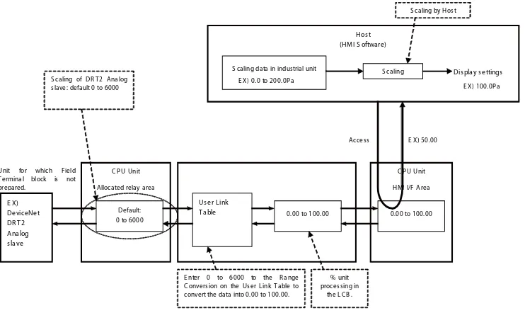
Analog signals of Analog I/O Unit for which Field Terminal Block is not prepared (DeviceNet DRT2 Analog Terminal, etc.) can be taken in through "User Link Table".
User Link Table is utilized when data is exchanged between the CPU Unit and Loop Controller. The input value of DRT2 Analog Terminal is taken into the memory area of the CPU Unit; therefore, the Loop Controller can acquire the input data through the User Link Table.
Number of external contact I/O points used for the system
Determine the necessary contact input/output number and how many of them will be controlled by the Loop Controller.
Unit Specification Type Block Name
Analog Input/Output Unit
4 inputs (1 to 5 V, 4 to 20 mA, etc.)
CJ1W-MAD42 Ai4-point/Ao2-point
Terminal (Block Model 592)
2 outputs (1 to 5 V, 0 to 10V, etc.)
Analog Input Unit 4 inputs (1 to 5 V, 4 to
20 mA, etc.)
CJ1W-AD041-V1 Ai4-point Terminal
(Block Model 586) 8 inputs (1 to 5 V, 4 to
20 mA, etc.)
CJ1W-AD081-V1 Ai8-point Terminal
(Block Model 584) Analog Output Unit 4 outputs (1 to 5 V/ 4 to
20 mA, etc.)
CJ1W-DA041 Ao4-point Terminal
(Block Model 587) 8 outputs (1 to 5 V,
etc.)
CJ1W-DA08V Ao8-point Terminal
(Block Model 585)
8 outputs (4 to 20 mA) CJ1W-DA08C Ao8-point Terminal
(Block Model 585) 2 outputs (1 to 5 V/ 4 to
20 mA, etc.)
CJ1W-DA021 Ao2- point Teminal
(Block Model 591) Isolated-type
Thermo-couple Input Unit
4 inputs (B, E, J, K, L, N, R, S, T, U, WRe5-26, PLII, mV)
CJ1W-PTS51 Ai4- point Terminal
(Block Model 566)
2 inputs (B, E, J, K, L, N, R, S, T, U, WRe5-26, PLII)
CJ1W-PTS15 Ai2- point Terminal
(Block Model 571)
Isolated-type Resis-tance Thermometer In-put Unit
4 inputs (Pt100, JPt) CJ1W-PTS52 Ai4- point Terminal
(Block Model 567)
2 inputs (Pt100, JPt100, Pt50, Ni508.4)
CJ1W-PTS16 Ai2- point Terminal
(Block Model 571) Isolated-type DC Input
Unit
2 inputs (1 to 5 V, 4 to 20 mA, etc.)
CJ1W-PDC15 Ai2-point Terminal
Design
Section 2-1
Number of analog/contact I/O points used on the Loop Controller
How many analog/contact signal data will be exchanged between the Loop Controller and CPU Unit in the inner processing of PLC-based Process Control System?
"User Link Table", the table through which LCB can exchange data with CPU Unit enables pro-gramming for the Loop Controller, such as wiring Function blocks and creating sequence table without knowing the I/O Memory address in the CPU Unit.
Current Consumption
Confirm if the current consumption of the Units mounted on the rack is less than the current capac-ity of the Power Supply Unit.
Evaluation of Load Rate
The Loop Controller cyclically processes operation of its own function blocks asynchronously with I/O refreshing of the CPU Unit. The cycle by which operations are processed, or the "operation cy-cle," is dependent on the type and number of function blocks used.
For this reason, when many function blocks whose operation takes a long time to process are used, the actual operation cycle of the entire Loop Controller or an individual function block increases. As a result, the desired preset operation cycle sometimes cannot be satisfied.
The ratio between the actual execution time required for processing operation and the preset op-eration cycle is called the "load rate." The maximum values and current value of each opop-eration cycle group can be confirmed on CX-Process Tool. A load rate of 80% or less is required in all op-eration cycle groups on this Loop Controller.
The High Load Alarm Flag (A42408) turns ON if the load rate exceeds 80% for 6 seconds. If this happens, select the function blocks that can have longer operation cycles and increase their oper-ation cycles. If the load rate is still too high, add on a CPU Unit or a CPU Unit and a Loop Control Unit and distribute function block processing between the mounted Units.
Maximum number of loops
The load rate of the Loop Controller should be 80% or less; therefore, in general cases, such as when each loop consists of an Ai4-point Terminal, a Segment Linearizer, a Basic PID, and an Ao4-point Terminal block, the maximum number of control loops would be as shown in the following ta-bles.
Loop-control CPU Units CJ1G-CPU43P/44P/45P (LCB03)
CJ1G-CPU42P (LCB01) Operation cycle Maximum
num-ber of loops
Operation cycle Maximum num-ber of loops
Operation cycle Maximum num-ber of loops
0.01s 20 loops 0.02 s 35 loops 0.05 s 70 loops
0.1 s 100 loops 0.2 s 150 loops 0.5 s 150 loops
1 s 150 loops 2 s 150 loops
Operation cycle Maximum num-ber of loops
Operation cycle Maximum num-ber of loops
Operation cycle Maximum num-ber of loops
Evaluation of External I/O Response Cycle (Dependent on CPU Unit's Cycle Time)
The operating speed (operation cycle) itself of each function block on the Loop Controller is not related to the CPU Unit's cycle time. However, as the CPU Unit's I/O memory is accessed during data exchange, for example, between Analog I/O Units and the Basic I/O Unit, the timing of data exchange is greatly influenced by the CPU Unit's cycle time.
The external analog I/O response cycle (equivalent to the I/O response cycle on a general control-ler) when the Loop Controller is configured as part of an instrumentation system is not the same as the operation cycle of the function blocks; but is a cycle heavily dependent on the CPU Unit's cycle time.
Total time of input conversion time, ladder cycle time, Loop Controller operation cycle and output conversion time is equal to operation cycle of a controller.
Design
Section 2-1
2-1-2
System Example
System Configuration
Execute Time-sharing proportional temperature control with the PV input of temperature and con-trol object of SSR.
Input the RSP from the Ramp Program as a SP of the temperature control.
Configuration, monitoring, and tuning can be executed on the NS series PT (programmable termi-nal) sceens for the Loop Controller through Ethernet.
Initial setting and process programming are executed by CX-Process Tool installed on the personal computer which is coneected by serial communication.
T hermocouple type K
F unction block
F ield T erminal
Ai
C ontroller C onverter
S etting device
S egment Program
F ield T erminal
Di
S witch
(F or centralized monitoring) HMI Software
NS s eries (F or monitoring)
E thernet
E thernet unit (Unit No.1) C X-P rogrammer
C X-P roces s T ool (F or development)
MV 0.0 to 500.0 degree
R amp program
T emperature s etting device
P ID R S P
(S S R )
Heater P V (temperature) P V
T emperature controller
T hermocouple S S R
Digital output unit: C J 1W-OD211
T hermocouple Input Unit: C J 1W-P T S 51 (Unit No.0)
S erial Ins trumentation Diagram
Analog/P uls e
Solid state relay
Advanced
Details of the control
Build control system described below.
Loop Control
Temperature control of time-sharing proportional PID is peformed according to the Segment Pro-gram. The SP is changed at the time set in the Segment ProPro-gram.
Analog signal (MV) from PID is converted into time-sharing ON/OFF signal by Analog/Pulse Width Converter to control a heater by operating SSR which is controlled by contact signal (transistor) to which voltage is applied from external source.
Sequence Control
Pepare the program for a simple sequence control operation below.
Operation 1 described below is performed when Condition1 or Condition2 is met.
Condition1: (When both of the two conditions below are met.)
High High Limit alarm (HH) output of the temperature controller is ON.
Auto is selected for Auto/ Manual
Condition 2
Emergency stop button is turned ON. (Internal contact allocated in the PLC I/O Memory)
Operation 1
MV is set to 0%.
The lamp is turned ON.(Turn ON the internal contact allocated in the PLC I/O Memory).
S P
T emperature s etting device
Analog/P uls e C onvers ion ON/O F F Output
OR P ID
P V (T emperature)
Upper upper-limit (HH)
ON
Design
Section 2-1
Units used in this system
Function blocks used in this system
MEMO: Execution order of Function Block
The execution proceeds in the following order: Field Input Terminal, Control/Operation Block (in the order of Block Address *1), Field Output Terminal.
*1: User defined order can be set for the execution (Specify the execution order in ITEM005: Exe-cution order). It is also possible to execute the program in the order of location on the Block Dia-gram. (Select Settings - Setting Operation Order).
Connected De-vice
Unit Model Unit Type Unit No. for
ien-tification
Terminal which is connected.
- CJ series CJ1G-CPU4*P CPU Unit with
Pre-installed
CJ1W-PTS51 Special I/O Unit Unit No.0 Input No.1
Solid State Re-lay (SSR)
Output Unit CJ1W-OD211 Basic I/O Unit Output No.1
Ethernet to Per-sonal Computer
Ethernet Unit CJ1W-ETN21 CPU Bus Unit Unit No.1
Function Block Type Block Model Block Name
Program setting Operation Block 157 Segment Program 2
Thermocouple Input Field Terminal 566 Ai4-point Terminal
(PTS51)
PID operation Control Block 012 Advanced PID
Analog/Pulse Width Converter
Operation Block 192 Analog/Pulse Width
Converter (Analog Input ON/OFF
period ratio conver-sion)
Digital Output Field Terminal 514 Do16-point Terminal
(OD211)
Details of the Sequence Operation
Loop Controllers can perform sequence control based on its "Sequence Table" or "Step Ladder". However, only "Step Ladder" can be utilized for the Loop-control CPU Unit.
Sequence Logic 1
ConditionsManipulation
Sequence Logic 2
ConditionsField Terminal
PV
Block Model 012
MV Segment Program2
Block Model 157
PID Thermocouple Input Unit
Program Setting
Output Unit Y1
Do16-point Terminal (OD211)
Block Model 514 RSP
Analog/ Pulse Width Converter
PWM Block model
192
User Link Table
CPU Unit
Step Ladder Control Contact
Condiitons Data for Condition Judgement
High/High Limit alarm (HH) output of Temperature Controller is ON
PID ITEM013 (High/High Limit (HH) Alarm output) is ON
Auto is set in Auto/ Manual PID ITEM086 (A/M switch)=ON
Manipulaton Value to be Manipulated
Set MV to 0%. PID ITEM080 (Preset MV switch) = ON
PID1 ITEM081 (Preset MV value) is set to 0, before.
Turn ON the Lamp. 0100CH 00 bit (Internal contact allocated in the PLC
I/O Memory) = ON
Conditions Data for Condition Judgement
Emergency Stop Button is ON 0200CH 00 bit (Internal contact allocated in the PLC
Design
Section 2-1
Manipulation
Explanation of Step Ladder
Sequence operation can be programmed in Ladder language for the Loop Controller.
Step Ladder is programmed in the Function block of Block Model 301. Maximum 200 blocks can be pasted (Allocated to Block address 701 to 900).
The Step Ladder Program block is used in the following cases:
When logical operations such as AND, OR and NOT are to be performed on the Loop Control-ler
When input of changes in the contact state (OFF to ON or ON to OFF) are to be converted to one-shot contact outputs that are ON for only one operation cycle
When system contacts such as constantly ON contacts are to be used on the Loop Controller
When step progression control, for example, is to be performed on the Loop Controller
ITEMs that can be specified by sequence commands are ITEMs whose ITEM category is "con-tact input" or "con"con-tact output." For details, see the Setting Method item in the ITEM lists in the descriptions for each function block.
Stap ladder can be used to execute sequence control which is necessary for the loop control. It is useful to use step ladder for switching auto/ manual or alarm handling. Step ladder is not suit-able for high speed or complex sequence control. For high speed or complex sequence control applications, use ladder proram of the CPU Unit.
Manipulaton Value to be Manipulated
Set MV to 0%. PID ITEM080 (Preset MV switch) = ON
PID1 ITEM081 (Presset MV value) is set to 0, be-fore.
Turn ON the Warning Lamp. 0100CH 00 bit (Internal contact allocated in the PLC
I/O Memory) = ON
Command type Settable ITEM type "According to Step Ladder Program" at
"Setta-ble Method" Item Input type commands such
as LOAD
Contact output R (read-enabled)
Contact input R/W (read/write-enabled)
Output type commands such as OUT
Contact input S tep Ladder (B lock model 301)
One of
Lgical operations S ys tem contact us e S tep progres s ion control
User Link Table used in this system
Explanation of the User Link Table
The User Link Table is a table in the Loop Controller that is used to exchange data with the CPU Unit.
Set the necessary data in each line, including the user-defined tag name and other parameters such as the CPU Unit's I/O memory address, 0%/100% scaling values, refresh period, and function block ITEMs to be read/ written.
Each tag can read or write data in the specified CPU Unit I/O memory for the specified conditions. It is also possible to exchange data regularly or refresh a particular function block's ITEM data when there is a change in the CPU Unit's I/O memory. Up to 2,400 tags can be created.
Use the CX-Process Tool to register tags in the User Link Table.
Once the tags have been registered in the User Link Table, the tag names can be used in Loop Controller programming such as connections or sequence tables, so it isn't necessary to know the specific CPU Unit I/O memory addresses associated with each tag when programming.
The User Link Table can also be pasted in a block diagram as a virtual function block.
Scaling
PID: 0.0 to 500.0°C
MEMO: Scaling performed by the Loop Controller
Analog data in the Loop Controller is handled in percentage unit (0 to 100.0%).
In Loop Controller, scaling data can be set for each Function block. The scaling data is included in CSV tags. HMI software or PT utilizes the CSV tags for communication with the CPU Unit. Exaple: For PID Function block, scaling settings for SP and PV is common.
Refer to Appendix3-4 Scaling.
Conditions
Operation cycle: 0.1 s
Start Mode at power ON: Cold start
EM bank No.0 is utilized for HMI data area
HMI Function operation cycle: 0.1 s
Data Writing Direction Tag Name I/O Memory Address of CPU Unit
CPU Unit to Loop Controller Emergency Stop 200.00
Loop Controller to CPU Unit Lamp 100.00
C P U Unit
F unction B lock Data
Us er Link T able T ag A T ag B T ag C
I/O Memory E quivalent
V irtual Link T able B lock
T ag A T ag C
Design
Section 2-1
Operation Cycle
All of the function blocks (for example, all Field Terminals and the Step Ladder Program block) on the Loop Controller are executed cyclically.
Basically, all function blocks (including the Step Ladder Program block) are executed at a default common operation cycle of one second that is set in the System Common block (Block Model 000). (There are some function blocks whose operation cycle is set to not common operation cycle but 1 s.)
To change the system common operation cycle to a value other than one second, set one of the following values to the system common operation cycle (ITEM004) of the System Common block (Block Model 000).
1: 0.1 sec, 2: 0.2 sec, 3: 0.5 sec, 4: 1 sec, 5: 2 sec (default is 4: 1 sec)
When changing the operation cycle of a specific function block, change ITEM004 (operation cycle) of the respective function block to one of 1: 0.1 sec, 2: 0.2 sec, 3: 0.5 sec, 4: 1 sec, 5: 2 sec, 6: 0.01 sec, 7: 0.02 sec, or 8: 0.05 sec from the default "0: common to each block."
Start Mode at Power ON
There are three ways that the Loop Controller can start operation: a hot start, a cold start and a hot start within specified time. With the default settings, the Loop Controller will perform a hot start when the power is turned ON or the Loop Controller is restarted. To start operation in hot start with-in specified time when the power is turned ON or the Loop Controller is restarted, set "0" (hot start within specified time) to the ITEM018 of the System Common Block (Model000). To start operation in cold start, set "2" (cold start) to the ITEM018 of the System Common Block (Model000).
Hot start within specified time
When operation is started in hot start mode (ITEM018 = 0), a hot start is performed after recovering from a power interruption if the time that power is interrupted is a within the time specified in ITEM037 (Hot start enabled time: 0 to 3,600 s (1 hour)). Cold starts are performed if power is in-terrupted for longer than this time.
Cold start
Use the cold start method when it isn't necessary to continue operation with the same values that existed before the power was turned OFF and it is acceptable for the Board to start operation with the following settings: Local Set Point, MV = 0, and Manual mode.
Hot start
Use the hot start method when it is preferable to continue operations after a short power interrup-tion or it is necessary to use the same Remote/Local setting, MV output value, and Auto/Manual setting that existed before the power went OFF.
Hot starts are not performed and cold starts are performed after power interruption of 24 hours.
HMI Function
HMI software and PT read/ write the ITEM of Control/Operation Block, External Control Block, and System Common Block via this allocated HMI I/Fdata area.
See Appendix3-1 HMI Function for reference.
The EM bank number where the ITEM data is allocated (known as the HMI data area) is spec-ified by ITEM050 of the System Common Block (block model 000.) The setting range for the HMI EM bank number is 0 to 12.
The refresh period for the HMI data is specified by ITEM051 of the System Common Block (block model 000.) ITEM051 is known as the "HMI function's operation cycle".
CPU Unit
E M area (Human-machine
interface data area)
Loop C ontroller
I/O Memory
and read data. C ontrol block
ITE Ms
Operation block ITE Ms
E xternal controller block ITE Ms
At each Operation Cycle *1 Human-machine
interface Function System
common blocks ITE Ms
*1: S pecify the human-machine interface function's operation cycle time (in seconds) with ITE M 051 of the S ystem C ommon Block (Block model 000).
HMI Software or PT
Specify CSV tag
Setting up the Hardwares.
Section 2-2
2-2
Setting up the Hardwares.
This chapter describes the procedure to set up the hardwares designed in "Step1. Design".
1. Installing and wiring the Loop Control Board and Analog I/O Unit.
The Loop Controller is built in the Loop-control CPU Unit (CJ1G-CPU**P); therefore, it is not nec-essary to install and wire the Loop Controller.
2. Wiring Analog I/O Unit and Communication Unit
Example
Unit Type Wiring
Thermocouple Input Unit CJ1W-PTS51 Input 1 (Wire the thermocouple to B4+ and A4-)
Digital Output Unit CJ1W-OD211 Output 1 (B8: Common)
Ethernet Unit CJ1W-ETN21 Twisted-pair cable
C X-One C X-P rogrammer C X-P roces s T ool
E thernet Unit (Unit No.1)
SSR S erial C ommunication
T hermocouple T ype-K
Loop-control CPU Unit CJ1W-CPU**P
Thermocouple Input Unit CJ1W-PTS51 (Unit No.00)
Digital Input Unit CJ1W-OD211
B 4 A4
+ + T hermocouple
Type K
B 0
B 8
CJ1W-OD211 C J1W-E T N21
S C R
Ethernet cable
3. Setting the Unit Number and Node Address
(1)Set the No. below for each unit.
Special I/O Unit (Ex. Analog I/O Unit): Unit number 0 to 95
NOTE: If two or more Special I/O Units are assigned the same unit number, a "UNIT No. DPL ERR" error (in the Programming Console) will occur and PLC will not continue operation. "ERR/ ALM" LED on the CPU Unit will be lit.
CPU Bus Unit (Example: Ethernet unit):Unit number 0 to F(digit hexadecimal: 0-15), Node No. 01 to FE (1 to 254 decimal)
Note: Do not set a Unit number that has already been set for another CPU Bus Unit. If a Unit No. is duplicated, "ERC" indicator on the CPU Bus Unit will be lit.
Example
Unit No, Node No,
Unit Name Model Unit Type Rotary switch
Thermocouple Input Unit
CJ1W-PTS51 Special I/O Unit Unit No.: 0
Ethernet Unit CJ1W-ETN21 CPU Bus Unit Unit No.: 1
Initial Setting of PLC on CX-Programmer.
Section 2-3
2-3
Initial Setting of PLC on CX-Programmer.
This chapter describes the procedure of initial setting of PLC with CX-Programmer.
In case that the PLC model or communication method is unknown, Auto Online enables auto-matic connection with connected PLC, recognizing the PLC model and communication method. When Auto Online is executed, it is possible to upload and monitor the program after connecting CX-Programmer and PLC. (In case that CX-Programmer is connected to PLC by Auto Online, it is not necessary to execute 2) Starting a New Project on CX-Programmer, 3) Setting the De-vice Type, and 4) Setting the Network Type.
Procedure: Select PLC - Auto Online - Auto Online. A "New Project" will be automatically cre-ated. The Program, PLC Settings, and I/O Table are uploaded from the PLC. Auto Online can be utilized when Communication Settings of PLC is set to any of 9600(default), 19200, 38400, or 115200 bit/s and communicaton mode is set to either of Tool Bus or Host Link.
1. Starting CX-Programmer
Start the CX-Prorammer following the procedure described below.
Program - Omron - CX-One - CX-Programmer - CX-Programmer. CX-Programmer can be started from the CX-Integrator, too.
2. Starting a New Project on CX-Programmer
Use the following procedure to create a new project. Select File - New.
Personal Computer CX-Programmer
Initial setting
CPU Unit
Serial communication
3. Setting the Device Type
(1)Change PLC dialogue box will be displayed on the display
(2)Select Device Type in the pull-down list to specify the PLC type.
(3)Click the Settings button.
(4)Set the CPU Type (CPU** in the table above) and click the OK button.
4. Selecting the Network Type
Set the network type to communicate with PLC.
(1)For serial comunciation, select Toolbus. Connect the personal computer to the CPU Peripheal port.
(2)Click the OK button.
Note: The network settings must be identical to the settings in the CPU Unit.(DIP sw and PLC Set-tings).
PLC series Device type to be set.
Loop-Control CPU Unit CJ1G-CPU42P CJ1G-CPU42H
CJ1G-CPU43P CJ1G-CPU43H
CJ1G-CPU44P CJ1G-CPU44H
Initial Setting of PLC on CX-Programmer.
Section 2-3
5. Connecting the Personal Computer and CPU Unit with Serial Cable.
Connect CX-Programmer to the CPU Unit with a serial cable. (CPU Peripheral port or RS232C port)
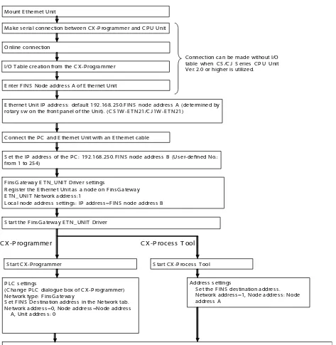
Refer to Appendix3-2 Connections via Ethernet to directly connect the CX-Programmer to PLCs. via Ethernet
6. Setting the DIP Switch of the CPU Unit
Set the initial hardware configuration for the CPU Unit.
Set the parameters for Serial port (Peripheral or RS232C port) communication and automatic pro-gram transfer enabled/disabled when power is turned ON.
Example: When PLC Settings is in default setting.
When connecting to Peripheral port through Toolbus: SW4=OFF
When connecting to RS232C port through "SYSMAC WAY": SW5=OFF
7. Turning ON the PLC Power
Turn ON the PLC Power.
Connection Figure Network type
Direct serial con-netcion
Peripheral Bus (Tool-bus): Select Toolbus or
Host Link : Select SYS-MAC WAY
SW4: ON : Use peropheral port parameters set in the PLC Setup.
OFF: Auto-detect Programming console or CX-Programmer parameters at the periferal port. SW5: ON: Auto-detect CX-Programmer parameters at the RS232C port.
OFF: Use RS-232C port parameters set in the PLC Setup.
CX-Programmer
Serial connection
CJ series
Cables:
Connection to Peripheral port: CS1W-CN226/626 Connection to RS-232C port: XW2Z-200S-CV/500S-CV
Peripheral port
RS-232C Port
8. Going Online with the PLC and Creating I/O Tables
Allocate I/O Memory based on the actual I/O (Basic I/O Unit) and CPU Bus Unit.
Registered I/O table
The information of mounted unit type and locations of all Units is called "Resistered I/O tables". CPU Unit recognizes the mounted Units according to this information.
I/O tables can be created by the following two procedures: a) Create I/O table: Creating I/O tables based on mounted Units
b) Configure I/O table: I/O tables creation offline without mounted Units on the Pesonal Computer. The I/O tables are transferred to the CPU Unit.
I/O Memory address of DIO (contact I/O) and AIO (analog I/O)
I/O Memory address of DIO (contact I/O) is automatically determined by I/O table creation ac-cording to the mounted location of the Basic I/O Unit.
I/O Memory address of AIO (analog I/O) is determined with the rotary switchs (Unit No.) on the front panel of the Analog I/O Unit.
C X-P rogrammer G o online and create I/O T able.
C reating I/O T able
R egis tered I/O T able S lot No. Model
0 C J 1W-OD211
1 S pecial I/O Unit (Unit No.0) 2 S pecial I/O Unit (Unit No.1)
Initial Setting of PLC on CX-Programmer.
Section 2-3
"I/O table creation" Procedure
Create an I/O Table online following the steps below.
(1)Select PLC - Work Online. (Or, right-click on the PLC in the project tree and select Work On-line).
NOTE:When going online with the CPU Unit and connection can not be made with the message of "Failed to connect the PLC because the PLC type does not match.", right-click on the PLC in the project tree on the left window and select Change to change the Device Type or CPU Type. (2)Select PLC - Operating Mode - Program (or, double-click on the PLC in the project tree and select Operating Mode - Program).
(3)Select PLC - PLC Information - I/O Table (or, double click I/O Table on the project tree). (4)Select Option - Create.
Memory Allocation of each Unit on the CS/CJ series CPU Unit
Memory allocation of each Unit on the CS/CJ series CPU Unit differs depending on the Unit type. The table below shows the allocation of each Uint type.
Unit Type Example Allocated Area
CIO Area DM Area
1) Basic I/O Unit Contact I/O Unit I/O Area (0000 to 0319CH) Memory is allocated based on mounting position in the Racks.
-2) Special I/O Unit Analog I/O Unit Special I/O Unit Area (2000 to 2959CH) Each Unit is allocated ten words based on its unit number (0 to 95) setting.
DM Area for Special I/O Units (D20000 to 29599) is allocated 100 words for each Special I/O Unit based on unit number (0 to 95).
3) CPU Bus Unit Communication Unit in-cluding Ethernet Unit
CPU Bus Unit Area (1500 to 1899CH) Each unit is al-located 25 words based on its unit number setting (0 to F).
DM Area for CPU Bus Units (D30000 to 31599) is allocated based on unit number (0 to F).
I/O table creation
CS/CJ series
CX-Programmer
Registration
Information of the mounted Units is transferred to the CPU Unit
Basic I/O Unit (Contact I/O Unit)
When I/O tables are created with CX-Programmer, I/O words are automatically allocated for the Basic I/O Units based on the position that Units are mounted (from left to right order) in I/O Area (0000 to 0319CH).
NOTE:CH means Word data (16 bit).
Special I/O Unit, including Analog I/O Unit
Each Unit is allocated ten words in the Special Unit I/O Area (2000 to 2959CH) based on its unit number (0 to 95) setting.
Each Special I/O Unit is allocated 100 words in DM Area for Special I/O Units (D20000 to 29599) based on the unit number (0 to 95).
Example: Analog I/O Unit
Operation data such as Analog Input/Output values are allocated in Special I/O Unit Area (2000 to 2959CH).
15
Basic I/O Unit: Automatic alloction depending on the position.
PLC CPU Unit
From Left to Right order
0000CH Special I/O Unit: Allocation determined by rotary switch setting
Rotary Switch: Unit No.0 to 95
2000CH
Special I/O Unit Area CPU Unit
Special I/O Unit DM Area
15 0
Initial Setting of PLC on CX-Programmer.
Section 2-3
Initial setting values such as sensor/input type and settings for rate of change are allocated in DM area for Special I/O Units (D20000 to 29599). (This area is used to set the user-defined settings).
CPU Bus Unit, including Communication Unit
Each unit is allocated 25 words in the CPU Bus Unit Area (1500 to 1899CH) based on its unit num-ber setting (0 to F) set by roraty switch. Each Unit is allocated 100 words in the DM Area for CPU Bus Units (D30000 to 31599) based on its unit number (0 to F).
Access Method of LCB to DI/O and AI/O
LCB inputs/outputs contact signal or analog signal from/to an external device, by exchanging data with contact or analog I/O Units.
Data exchange requires the operation below on the CX-Process Tool.
(1)Field Terminal block which corresponds to the Input/Output Unit must be registered on the Block Diagram.
(2)To corelate the Field Terminal block with the Unit, it is necessary to set the following:
For Contact I/O block, enter leading word No, allocated to the Unit to the ITEM007 (CIO word No.).*1
For Analog I/O block, enter the Unit No, (0 to 95) which is set by the rotary switchs on the front panel of the unit to the ITEM007 (Unit No.).*2
*1: I/O Memory address of DI/O (Contact I/O) in the CPU Unit is automatically determined based on the mounted Basic I/O Unit location when I/O table is created.
*2: I/O Memory address of AI/O (Analog input) in the CPU Unit is determined based on the rotary switchs on the front panel of the Analog I/O Unit.
9. Setting Analog/ Process I/O Units
Settings for Process I/O Unit
Initial Setting of PLC on CX-Programmer.
Section 2-3
Settings for Thermocouple Input Unit CJ1W-PTS51 (Setting for
In-put Sensor type=K)
Double-click on the Unit (CJ1W-PTS51) in the I/O Table window of the PLC. Edit Parameters win-dow will be displayed. From the Displayed parameter, select Common (Initial settings area) and set K (with decimal point) for the Input Sensor type.
10. Transferring the DM Area for Special I/O Unit to the CPU Unit
Transfer DM Area for Special I/O Unit to the CPU Unit.
(1)Select PLC - Work Online on the CX-Programmer.
(2)On the PLC Memory window, select PLC - Transfer - to PLC.
C X-P rogrammer DM Area s etting O nline connection and trans fer T rans fer
C P U Unit
DM Area S ettings PLC Memory
Addres s D20030 D20040 D20030
Programming Offline for Loop Controller.
Section 2-4
2-4
Programming Offline for Loop Controller.
1. Starting CX-Process Tool
Start the CX-Process Tool from the Start button in the Microsoft Windows taskbar. Select Omron
- CX-One - CX-Process Tool - CX-Process Tool.
NOTE: CX-Process Tool can be started with settings inherited from the CX-Programmer.
(OT)
S tep Ladder
Analog/Pulse Width C onverter
Di
User Link Table
Do
S etting Device
C ontrolle
P oint:
It is neces s ary to s elect Advanced – T ag S etting – C S V T ag.
C S V T ag (T ag name, S caling, and Unit).
F ield T erminal F unction block s electing by T ool S oftware. S oftware connection of F unction blocks . IT E M s etting for each
C S V C S V
NS face plate creation
F unction block P oint:
(Unit No,), s et the value s et by the rotary s witch on the front panel of the Unit.
P oint:
s eparately from B lock Diagram.
For FIeld terminal ITEM007
PID block -Settings
Complete the settings in
Point
Register CPU I/O Memory as a tag
Register and edit Step ladder
Function blocks tag settings
tag file creation (Compiling) To Lamp
From Switch
2. Starting a New Project
Next, start a new project by selecting File - New.
A folder to save the project file must be selected.
The window below will be displayed.
Specify a file name in the New Project Name field.
A new folder with the project name (Ex. PLC-based Process Control CJ) entered in this dialogue box will be created in the folder which was selected in 2). In the folder, a new prroject file (exten-sion: mul) with the same project name will be automamtically created (Ex. PLC-based Process ControlCJ.mul).
3. Creating (Inserting) a New Function Block File for the Node
(1) Select Settings - Insert - Insert Node.
(2)Insert LCB/LCU dialogue box below will be displayed.
Select Loop-control CPU Unit/Process CPU in the LC Type.
Programming Offline for Loop Controller.
Section 2-4
When V3.00 or later version is set for the LCB Unit Ver., the version can not be changed to Ver.2.00 or ealier version by executing Change LC Type. Check the LCB Unit Ver. before insert-ing the LCB.
(3)Function Block File for the Node will be displayed in the Project Workspace Tree. (4)Below is an example for Node00 [CJ1G-H CPU43].
4. Software Initial Setting for the Loop Controller
Set the initial settings common to each function block in the System Common block (Block Model 000).
Workspace Tree.
(2)Double-click on each ITEM and enter the value in the table below. Data settings for System Common block
NOTE: EM bank No. for CJ1G-CPU45P is selectable from No. 0 to 2.
ITEM Data Name Setting Discription Options Discription
004 System
com-mon opera-tion cycle (s)
1 0.1s 1: 0.1sec, 2:
0.2 sec, 3: 0.5 sec, 4: 1 sec, 5: 2 sec
Total program in the Loop Controller is cyclically pefomed every operation cycle. Specifies operation cycle.
018 Start mode at
power ON.
2 COLD start 0: Hot start
within speci-fied time 1: HOT start 2: COLD start
There are three ways that the Loop Con-troller can start operation:
·Hot start within specified time: A hot start performed after recovering from a power interruption within the specified time.
·COLD Start
Operation is started after all values in the program is initialized,
·HOT Start
Operation is started with values that ex-isted before the power was turned OFF.
050 EM Bank No. 0 EM Bank
No.0 (Note)
EM Bank No.: 0 to 1
Specifies allocated area for HMI inter-face and update cycle of HMI data area.
051 Operation
Programming Offline for Loop Controller.
Section 2-4
HMI Function
HMI Function always allocates ITEM data of the Function blocks in a specified EM bank in the CPU Unit.
HMI Software and PT read/write ITEMs in the Contol/Operation Block, External Control Block, and System Common Block thtough this allocated HMI data area.
Refer to Appendix3-1 HMI Function.
5. Registaring Function Blocks
Register necessary Function blocks.
Once a Function block is registered, it will be displayed on the Project Workspace.
(1)Select a Block Diagram to be pasted in the Project Workspace and double-click on it.
(2)Click the right mouse button at the pasting position in the Block Diagram window and click on the Register to select Function block type from the pop-up menu. In CX-Process Tool V3.0 or later version, Function blocks can be freely pasted on the desired position.
(3)Select Resister - Control Block. In the Insert FunctionBlock for Blick Diagram dialogue box, select Control Block for Function Block Type and 012: Advanced PID for Block Name.
(4)Select Resister - Control Block. In the Insert Function Block for Blick Diagram dialogue box, select Others, Contact Type Operation Teminal for Function Block Type and then spec-ify 192: Analog/Pulse Width Converter for Block Name.
Programming Offline for Loop Controller.
Section 2-4
(6)Select Resister - Field Terminal. In the Insert field terminal dialogue box, select 566 Ai 4-point (PTS51), 514 Do 16-point Terminal, 501 Di 8-point Termnal, and 512 Do 8-point Ter-minal for Block Name
(7)Click the Insert button. Block Address will be incremented by one.
Order of Execution in Block Diagram and Block Address
Block address of the Control block is automatically assigned in the order of registration, if it is not specified.
The order of execution is in the order of Input-type Field Terminal block, Control/ Operation block (in the order of block address), and Output-type Field Terminal block. Therefore, in the default set-ting, order of registration is equal to the order of execution.
6. Making Software Connection between Function Blocks
Make software connection between the analog signal and integrated values of the registered Func-tion blocks.
(1)Click on the ITEM for a starting point of the connection and the double-click an ITEM for the end point. Software connection will be made. To connect function blocks by going around other blocks, bent connection lines at right angles by clicking at the corner to bend.
P V
Ai4 T erminal
Block Model 566
Advanced P ID MV
S egent Program 2 Block Model 157
P ID T hermocouple Input Unit
Program Setting
Y 1
0 to 500 degree 0 to 100%
R S P
Analog P uls e W idth C onverter
F ield T erminal
Do16 T erminal (O D211)
B lock Model 514
Us er Link T able
C P U Unit I/O Memory
C ontact
C P U Unit I/O Memory
C ontact
= S caling value
C ontrol output unit S tep Ladder C ontrol C ontact (PTS51)
Block Model 012
PID PV PID MV
CSV tag settings for each Function block. Each ITEM is automatically regarded as a tag of the Function block.
Programming Offline for Loop Controller.
Section 2-4
Delete the line connected to the block first, and then delete the block. If the block is deleted first, registation of the deleted block will be left in the block of starting point. In such case, the ITEM data of starting point must be set to 0. Otherwise, the line cannot be changed.
To delete a line, select the line to be deleted, click the right mouse button (the line will be dis-played in red), and select Delete Line from the pop-up menu.
The ITEM name will be displayed if you point at the ITEM at the end point. Confirm ITEM names when making connections.
To change the position of a function block or line, select the block or line and drag it to the desired position.
(2)It is possible to insert annotations onto the block diagrams. Click the right mouse button and se-lect Annotations - Insert. To change the size of the font in the annotation, select the annota-tion, click the right mouse button to display the pop-up menu and select Annotations
-Selected Annotation - Font Size. (The default font size is 12 points.)
7. Setting ITEMs in Function Blocks
Setting Unit No. of Analog I/O Field Terminal Block
Set the Unit No. of Analog I/O Units which is set by the rotary switchs on the front panel to the ITEM007 (Unit No.) of analog I/O field terminal block (Ai 4-point, Ao 4-point).
Analog I/O Unit
Field Terminal
Setting Example: Unit No. (ITEM007) of Ai 4-point terminal (Block model 561) =00
Set the Unit No. of Analog I/O Unit in Data for Field Terminal blocks.
For the ITEM007 (Unit No.) of Analog I/O field terminal, set the correct Unit No. of Analog I/O Unit which is specified by rotary switchs on the front panel. If the wrong Unit No. is set to the ITEM, data of other Special I/O Unit will be input/output (read/written).
Settings for ITEMs for Advanced PID block (Block Model012)
Example:
Thermocouple Input Contact Output
Model CJ1W-PTS51 CJ1W-OD211
Rotaty switch setting 0
-Block model 566 514
Function block name Ai 4-point Do16-point
ITEM007 (Unit No./CIO CH) Unit No. 0 0CH
ITEM Data Description Setting Description Options
024 Set Point setting
mode
1 Remote/Local 0: Local only
Programming Offline for Loop Controller.
Section 2-4
8. Creating Step Ladder
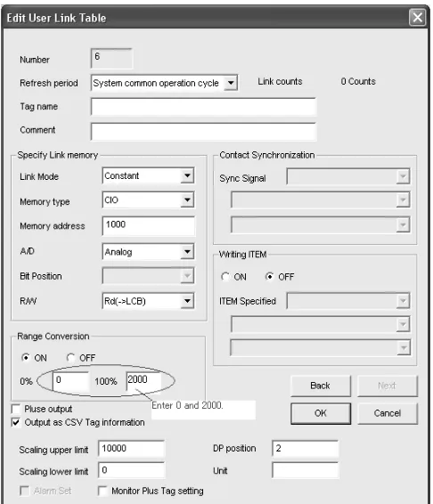
(1)Before starting step ladder creation, register CPU memory area to be used in the User Link Ta-ble.
Select Settings - Edit - User Link Table. The dialogue box shown below is displayed.