Automobile
Electrical and
Electronic
Systems
Fifth Edition
This textbook will help you learn all the skills you need to pass all Vehicle Electrical and Electronic Systems courses and qualifications.
As electrical and electronic systems become increasingly more complex and fundamental to the workings of modern vehicles, understanding these systems is essential for automotive technicians. For students new to the subject, this book will help to develop this knowledge, but will also assist experienced technicians in keeping up with recent technological advances. This new edition includes information on developments in pass-through technology, multiplexing, and engine control systems. In full colour and covering the latest course specifications, this is the guide that no student enrolled on an automotive maintenance and repair course should be without.
Designed to make learning easier, this book contains:
• Photographs, flow charts, quick reference tables, overview descriptions and step-by-step instructions. • Case studies to help you put the principles covered into a real-life context.
• Useful margin features throughout, including definitions, key facts and ‘safety first’ considerations. • Free access to the support website where you will find lots of additional information and useful learning
materials: www.automotive-technology.org.
Tom Denton is a Fellow of the Institute of the Motor Industry, a Member of the Institute of Road Transport
Automobile
Electrical and
Electronic
Systems
Fifth Edition
Fifth edition published 2018 by Routledge
2 Park Square, Milton Park, Abingdon, Oxon, OX14 4RN and by Routledge
711 Third Avenue, New York, NY 10017
Routledge is an imprint of the Taylor & Francis Group, an informa business
© 2018 Tom Denton
All rights reserved. No part of this book may be reprinted or reproduced or utilised in any
form or by any electronic, mechanical, or other means, now known or hereafter invented, including photocopying and recording, or in any information storage or retrieval system,
without permission in writing from the publishers.
Trademark notice: Product or corporate names may be trademarks or registered
trademarks, and are used only for identification and explanation without intent to infringe. First edition published 1996 by Arnold, a member of Hodder Headline plc.
Fourth edition published 2012 by Routledge
British Library Cataloguing-in-Publication Data
A catalogue record for this book is available from the British Library
Library of Congress Cataloging-in-Publication Data
Names: Denton, Tom, author.
Title: Automobile electrical and electronic systems / Tom Denton.
Description: 5th edition. | Abingdon, Oxon ; New York, NY : Routledge, 2017. | Includes bibliographical references and index.
Identifiers: LCCN 2017002757 | ISBN 9781138310490 (hardcover) | ISBN 9780415725774 (pbk. : alk. paper) | ISBN 9781315856629 (ebook) Subjects: LCSH: Automobiles—Electric equipment. | Automobiles—
Electronic equipment.
Classification: LCC TL272 .D43 2017 | DDC 629.2/7—dc23 LC record available at https://lccn.loc.gov/2017002757 ISBN: 978-1-138-31049-0 (hbk)
ISBN: 978-0-415-72577-4 (pbk) ISBN: 978-1-315-85662-9 (ebk)
Typeset in Arial
Preface xxiii
Acknowledgements xxv
Chapter 1 Electrical and electronic principles
1
1.1 Safe working practices 1
1.1.1 Introduction 1
1.1.2 Risk assessment and reduction 1
1.2 Basic electrical principles 1
1.2.1 Introduction 1
1.2.2 Electron flow and conventional flow 2
1.2.3 Effects of current flow 3
1.2.4 Fundamental quantities 4
1.2.5 Describing electrical circuits 4 1.2.6 Conductors, insulators and semiconductors 5 1.2.7 Factors affecting the resistance of a conductor 5 1.2.8 Resistors and circuit networks 5 1.2.9 Magnetism and electromagnetism 7 1.2.10 Electromagnetic induction 8
1.2.11 Mutual induction 8
1.2.12 Definitions and laws 8
1.3 Electronic components and circuits 11
1.3.1 Introduction 11
1.3.2 Components 11
1.3.3 Integrated circuits 15
1.3.4 Amplifiers 16
1.3.5 Bridge circuits 19
1.3.6 Schmitt trigger 19
1.3.7 Timers 20
1.3.8 Filters 20
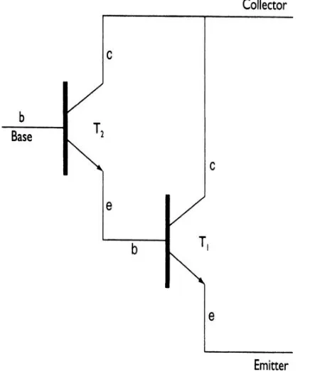
1.3.9 Darlington pair 22
1.3.10 Stepper motor driver 22
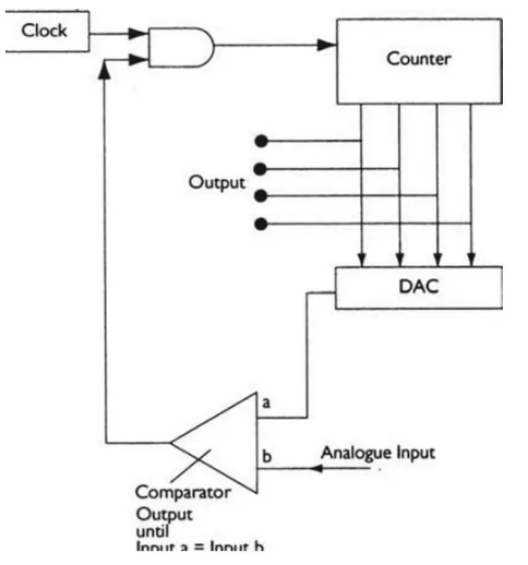
1.3.11 Digital-to-analogue conversion 23 1.3.12 Analogue-to-digital conversion 24
1.4 Digital electronics 25
1.4.1 Introduction to digital circuits 25
1.4.2 Logic gates 25
Contents
vi
1.4.3 Combinational logic 26
1.4.4 Sequential logic 27
1.4.5 Timers and counters 28
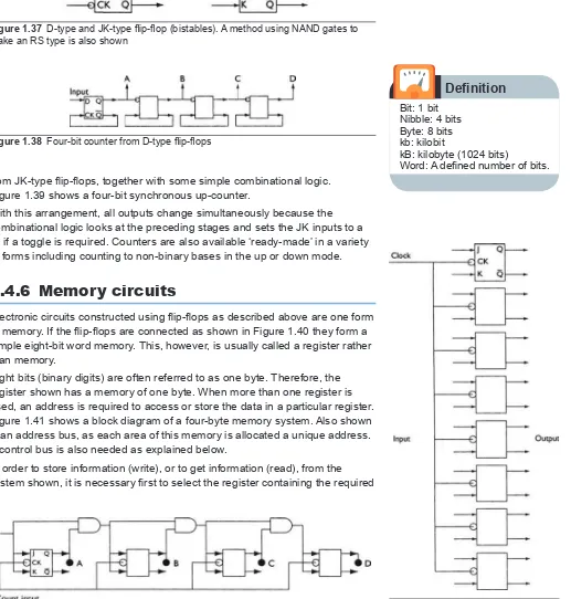
1.4.6 Memory circuits 29
1.4.7 Clock or astable circuits 31
1.5 Microprocessor systems 31
1.5.1 Introduction 31
1.5.2 Ports 31
1.5.3 Central processing unit (CPU) 32
1.5.4 Memory 32
1.5.5 Buses 32
1.5.6 Fetch–execute sequence 33 1.5.7 A typical microprocessor 33
1.5.8 Microcontrollers 35
1.5.9 Testing microcontroller systems 36
1.5.10 Programming 36
1.6 Measurement 37
1.6.1 What is measurement? 37 1.6.2 A measurement system 38 1.6.3 Sources of error in measurement 38
1.7 Sensors 40
1.7.1 Thermistors 40
1.7.2 Thermocouples 41
1.7.3 Inductive sensors 42
1.7.4 Hall Effect 43
1.7.5 Strain gauges 44
1.7.6 Variable capacitance 45
1.7.7 Variable resistance 46
1.7.8 Accelerometer (knock sensors) 48 1.7.9 Linear variable differential transformer
(LVDT) 50
1.7.10 Hot wire air flow sensor 51 1.7.11 Thin film air flow sensor 52
1.7.12 Vortex flow sensor 52
1.7.13 Pitot tube 53
1.7.14 Turbine fluid flow sensor 53
1.7.15 Optical sensors 54
1.7.16 Oxygen sensors 54
1.7.17 Light sensors 55
1.7.18 Thick-film air temperature sensor 56
1.7.19 Methanol sensor 56
Contents
vii
1.7.21 Oil sensor 57
1.7.22 Dynamic vehicle position sensors 57
1.7.23 Summary 58
1.8 Actuators 59
1.8.1 Introduction 59
1.8.2 Solenoid actuators 59
1.8.3 EGR valve 60
1.8.4 Motorized actuators 61
1.8.5 Stepper motors 62
1.8.6 Synchronous motors 66
1.8.7 Thermal actuators 66
1.9 Testing electronic components, sensors and
actuators 66
1.9.1 Introduction 66
1.9.2 Testing sensors 67
1.9.3 Testing actuators 68
1.10 Updates 69
1.10.1 Sensors overview and
developments 69
Chapter 2 Tools and equipment
71
2.1 Basic equipment 71
2.1.1 Introduction 71
2.1.2 Basic hand tools 71
2.1.3 Accuracy of test equipment 71
2.1.4 Multimeters 74
2.1.5 Logic probe 75
2.2 Oscilloscopes 77
2.2.1 Introduction 77
2.2.2 Waveforms 78
2.3 Scanners/fault code readers and analysers 79 2.3.1 On-board diagnostics introduction 79 2.3.2 Serial port communications 79 2.3.3 OBD2 signal protocols 80 2.3.4 Entry level scanners 81 2.3.5 Bosch KTS diagnostic equipment 86
2.3.6 Engine analysers 88
2.4 Emission testing 90
2.4.1 Introduction 90
2.4.2 Exhaust gas measurement 90
2.4.3 Exhaust analyser 91
Contents
viii
2.5 Pressure testing 93
2.5.1 Introduction 93
2.5.2 Automotive pressure oscilloscope
transducer 94
2.5.3 Breakout boxes 96
2.6 Diagnostic procedures 96
2.6.1 Introduction 96
2.6.2 The ‘theory’ of diagnostics 96
2.7 Pass-through technology 97
2.7.1 Introduction 97
2.7.2 J2534 99
2.7.3 Hardware and software requirements 100
2.7.4 Legislation 100
2.7.5 OEM software and data links 101
Chapter 3 Electrical systems and circuits
103
3.1 The systems approach 103
3.1.1 What is a system? 103
3.1.2 Vehicle systems 104
3.1.3 Open loop systems 104
3.1.4 Closed loop systems 105
3.1.5 Summary 105
3.2 Electrical wiring, terminals and switching 105
3.2.1 Cables 105
3.2.2 Colour codes and terminal designations 106
3.2.3 Harness design 109
3.2.4 Printed circuits 112
3.2.5 Fuses and circuit breakers 113
3.2.6 Terminations 115
3.2.7 Switches 117
3.3 Multiplexing 119
3.3.1 Limits of the conventional wiring system 119
3.3.2 Multiplex data bus 121
3.3.3 Overview 121
3.3.4 Controller Area Network (CAN) 123
3.3.5 CAN data signal 125
3.3.6 Local Interconnect Network (LIN) 129
3.3.7 FlexRay 131
3.4 Media oriented systems transport (MOST) 134
3.4.1 Introduction 134
3.4.2 MOST network 134
3.4.3 Protocol 135
Contents
ix
3.4.5 Consumer device gateway 138
3.4.6 Summary 138
3.5 Automotive Ethernet 139
3.5.1 Introduction 139
3.5.2 Overview 139
3.6 Circuit diagrams and symbols 139
3.6.1 Symbols 139
3.6.2 Conventional circuit diagrams 140 3.6.3 Layout or wiring diagrams 140
3.6.4 Terminal diagrams 140
3.6.5 Current flow diagrams 140 3.7 Electromagnetic compatibility 140
3.7.1 Introduction 140
3.7.2 EMC problems 140
3.8 Central electrical control 145
3.8.1 Overview 145
3.8.2 Ford generic electronic module (GEM) 152 3.8.3 Communication between modules 153
3.8.4 Summary 157
3.9 Connected cars 158
3.9.1 Introduction 158
3.9.2 Smart cars and traffic systems 158
3.9.3 Wi-Fi cars 160
3.9.4 Bluetooth 161
3.9.5 Applications (apps) 162
3.9.6 Vision enhancement 163
3.9.7 Self-help 165
3.9.8 Big Brother 165
3.9.9 When computers go wrong 166
3.9.10 Summary 167
3.10 Updates 167
3.10.1 Multiplexing 167
3.10.2 Bluetooth to displace cables? 176 3.10.3 Update on 48 V technology 178
Chapter 4 Batteries
181
4.1 Vehicle batteries 181
4.1.1 Requirements of the vehicle battery 181 4.1.2 Choosing the correct battery 181 4.1.3 Positioning the vehicle battery 182
4.2 Lead-acid batteries 183
4.2.1 Construction 183
Contents
x
4.3 Maintenance, charging and testing batteries 186
4.3.1 Maintenance 186
4.3.2 Charging the lead-acid battery 186 4.3.3 Servicing batteries 189
4.3.4 Battery faults 189
4.3.5 Testing batteries 189
4.3.6 Safety 193
4.4 Advanced battery technology 193
4.4.1 Electrochemistry 193
4.4.2 Electrolytic conduction 194 4.4.3 Ohm’s law and electrolytic
resistance 194
4.4.4 Electrochemical action of the lead-acid
battery 195
4.4.5 Characteristics 197
4.4.6 Peukert’s law 198
4.5 Developments in electrical storage 198
4.5.1 Lead-acid 198
4.5.2 Alkaline 199
4.5.3 ZEBRA 201
4.5.4 Sodium sulphur 201
4.5.5 Swing 201
4.5.6 Fuel cells 202
4.5.7 Super-capacitors 205
4.5.8 Summary 205
4.6 Updates 207
4.6.1 Micro batteries research 207 4.6.2 Lead-acid batteries update 208 4.6.3 Battery diagnostics 210
Chapter 5 Charging
213
5.1 Requirements of the charging system 213
5.1.1 Introduction 213
5.1.2 Basic operating principles 213 5.1.3 Vehicle electrical loads 214 5.2 Charging system principles 216
5.2.1 Basic principles 216
5.2.2 Charging voltages 216
5.2.3 Charging circuits 217
Contents
xi
5.3 Alternators 226
5.3.1 Bosch compact alternator 226 5.3.2 Efficient alternators 228 5.3.3 Water-cooled alternators 229 5.3.4 Denso high-output alternators 230 5.3.5 Charging system testing procedure 230
5.4 Smart charging 231
5.4.1 Introduction and closed loop regulation 231 5.4.2 Open loop regulation 233
5.4.3 Engine performance 233
5.4.4 Fault conditions 235
5.4.5 Summary 235
5.5 Advanced charging system technology 235 5.5.1 Charging system – problems and
solutions 235
5.5.2 Charge balance calculation 238 5.5.3 Alternator characteristics 239 5.5.4 Mechanical and external
considerations 240
5.6 Updates 241
5.6.1 Alternator developments 241
Chapter 6 Starting
245
6.1 Requirements of the starting system 245 6.1.1 Engine starting requirements 245 6.1.2 Starting system design 247 6.1.3 Choosing a starter motor 248 6.2 Starter motors and circuits 250 6.2.1 Starting system circuits 250
6.2.2 Example circuits 250
6.2.3 Starter circuit testing 253 6.2.4 Principle of operation 254 6.2.5 DC motor characteristics 257
6.3 Types of starter motor 258
6.3.1 Inertia starters 258
6.3.2 Pre-engaged starters 259 6.3.3 Permanent magnet starters 261 6.3.4 Integrated starters 263 6.3.5 Electronic starter control 263 6.3.6 Starter installation 263 6.3.7 Belt-driven starter-generator 264
Contents
xii
6.4 Advanced starting system technology 265 6.4.1 Speed, torque and power 265
6.4.2 Efficiency 267
6.5 Updates 268
6.5.1 Electronic starter motor control and
stop-start system 268
6.5.2 Jump start without a battery 270
Chapter 7 Ignition
273
7.1 Ignition system fundamentals 273 7.1.1 Functional requirements 273 7.1.2 Generation of high tension 274 7.1.3 Advance angle (timing) 274 7.1.4 Fuel consumption and exhaust emissions 275 7.1.5 Contact breaker ignition 275
7.1.6 Plug leads 276
7.1.7 Ignition coil cores 278
7.2 Electronic ignition 278
7.2.1 Introduction 278
7.2.2 Constant dwell systems 279 7.2.3 Constant energy systems 279 7.2.4 Hall Effect pulse generator 279 7.2.5 Inductive pulse generator 280 7.2.6 Other pulse generators 281 7.2.7 Dwell angle control (open loop) 281 7.2.8 Current limiting and closed loop dwell 283 7.2.9 Capacitor discharge ignition 284 7.3 Electronic spark advance 285
7.3.1 Overview 285
7.3.2 Sensors and input information 286 7.3.3 Electronic control unit 287 7.4 Distributorless ignition 290 7.4.1 Principle of operation 290
7.4.2 System components 291
7.5 Coil on plug (COP) ignition 291 7.5.1 General description 291 7.5.2 Control of ignition 293
7.6 Spark plugs 293
7.6.1 Functional requirements 293
7.6.2 Construction 294
7.6.3 Heat range 295
7.6.4 Electrode materials 296
Contents
xiii
7.6.6 V-grooved spark plug 297 7.6.7 Choosing the correct plug 298 7.6.8 Spark plugs development 299
7.7 Summary 299
7.7.1 Overview 299
7.7.2 Testing procedure 301
7.8 Advanced ignition technology 303 7.8.1 Ignition coil performance 303
7.9 Updates 304
7.9.1 Spark plug electrode designs 304
Chapter 8 Fuel control
307
8.1 Combustion 307
8.1.1 Introduction 307
8.1.2 Spark ignition engine combustion process 307 8.1.3 Range and rate of burning 309
8.1.4 Detonation 311
8.1.5 Pre-ignition 311
8.1.6 Combustion chamber 312
8.1.7 Stratification of cylinder charge 312 8.1.8 Mixture strength and performance 313 8.1.9 Compression ignition (CI) engines 313 8.1.10 Combustion chamber design –
diesel engine 316
8.1.11 Summary of combustion 316 8.2 Engine fuelling and exhaust emissions 317 8.2.1 Operating conditions 317
8.2.2 Exhaust emissions 317
8.2.3 Other sources of emissions 318 8.2.4 Leaded and unleaded fuel 319 8.3 Emissions and driving cycles 320 8.3.1 Exhaust emission regulations 320
8.3.2 Test cycles 321
8.4 Fuel injection 324
8.4.1 Advantages of fuel injection 324
8.4.2 System overview 324
8.4.3 Components of a fuel injection system 328 8.4.4 Bosch ‘L’ Jetronic – variations 332 8.4.5 Bosch Mono Jetronic – single point
injection 333
Contents
xiv
8.5 Diesel fuel injection 339
8.5.1 Introduction 339
8.5.2 Injection overview 344
8.5.3 Diesel exhaust emissions 345 8.5.4 Electronic control of diesel injection 346
8.5.5 Rotary pump system 347
8.5.6 Common rail system 350
8.5.7 Electronic unit injection (EUI) –
diesel fuel 355
8.5.8 Diesel lambda sensor 357
8.6 Summary 358
8.6.1 Overview 358
8.6.2 Diagnosing fuel control systems 358 8.7 Advanced fuel control technology 359 8.7.1 Air–fuel ratio calculations 359
8.8 Updates 360
8.8.1 Under pressure... 360
8.8.2 Euro 6 overview 362
Chapter 9 Engine management
365
9.1 Combined ignition and fuel introduction 3659.1.1 Introduction 365
9.1.2 Variable inlet tract 366 9.1.3 Combustion flame and pressure sensing 366 9.1.4 Wide range lambda sensors 367 9.1.5 Injectors with air shrouding 367 9.2 Exhaust emission control 367
9.2.1 Engine design 367
9.2.2 Combustion chamber design 367
9.2.3 Compression ratio 368
9.2.4 Valve timing 368
9.2.5 Manifold designs 368
9.2.6 Charge stratification 368
9.2.7 Warm-up time 369
9.2.8 Exhaust gas recirculation 369
9.2.9 Ignition system 370
9.2.10 Thermal after-burning 370 9.2.11 Catalytic converters 370 9.2.12 Closed loop lambda control 373 9.3 Engine management systems 374
9.3.1 Motronic M3 374
9.3.2 DI-Motronic 385
Contents
xv
9.4 Other aspects of engine management 391
9.4.1 Introduction 391
9.4.2 Variable valve timing 391
9.4.3 Lean burn engines 394
9.4.4 Two-stroke engines 394 9.4.5 Combustion control system 395
9.4.6 Active cooling 397
9.4.7 Engine trends – spark ignition 399 9.4.8 Transonic combustion 400 9.4.9 Diagnosing engine management
systems 401
9.5 Advanced engine management technology 405 9.5.1 Speed density and fuel calculations 405 9.5.2 Ignition timing calculation 406
9.5.3 Dwell calculation 408
9.5.4 Injection duration calculation 408 9.5.5 Developing and testing software 409 9.5.6 Artificial Intelligence 411
9.5.7 Neural computing 412
9.6 Updates 413
9.6.1 Gasoline direct injection electronic
control technology 413
9.6.2 Common rail diesels – intelligent
injectors 415
9.6.3 eSupercharger 417
9.6.4 GPS data for powertrains, apps,
other systems 417
9.6.5 V6 diesel with electric turbocharging 418
9.6.6 Water injection 418
9.6.7 Cylinder deactivation 419
9.6.8 Dynamic skip fire 421
9.6.9 Diesel particulate filters 421
9.6.10 Miller cycle 424
9.6.11 Cooled EGR 426
9.6.12 Nissan variable compression (VC)
engine 427
Chapter 10 Lighting
429
10.1 Lighting fundamentals 429
10.1.1 Introduction 429
10.1.2 Bulbs 429
10.1.3 External lights 431
Contents
xvi
10.1.6 Headlight lenses 435
10.1.7 Headlight levelling 436 10.1.8 Headlight beam setting 438
10.2 Lighting circuits 439
10.2.1 Basic lighting circuit 439
10.2.2 Dim-dip circuit 439
10.2.3 General lighting circuit 441 10.2.4 Flow diagram lighting circuit 442 10.2.5 Central lighting control circuit 442 10.2.6 Testing procedure 442 10.3 Gas discharge, LED and infrared lighting 445 10.3.1 Gas discharge lamps 445
10.3.2 Xenon lighting 447
10.3.3 Ultraviolet headlights 449
10.3.4 LED lighting 450
10.3.5 Infrared lights 451
10.4 Other lighting techniques 452 10.4.1 Mono-colour signal lamps 452
10.4.2 Linear lighting 452
10.4.3 Neon technology 452
10.4.4 Bending Light 453
10.4.5 Intelligent front lighting 454 10.5 Advanced lighting technology 455 10.5.1 Lighting terms and definitions 455 10.5.2 Single light-source lighting 456
10.6 Updates 457
10.6.1 BMW laser headlamps 457
Chapter 11 Auxiliaries
459
11.1 Windscreen washers and wipers 459 11.1.1 Functional requirements 459
11.1.2 Wiper blades 460
11.1.3 Wiper linkages 460
11.1.4 Wiper motors 462
11.1.5 Windscreen washers 462 11.1.6 Washer and wiper circuits 464 11.1.7 Electronic control of windscreen
wipers 466
Contents
xvii
11.2 Signalling circuits 470
11.2.1 Introduction 470
11.2.2 Flasher units 470
11.2.3 Brake lights 472
11.2.4 Indicators and hazard circuit 472 11.3 Other auxiliary systems 473
11.3.1 Electric horns 473
11.3.2 Engine cooling fan motors 474 11.3.3 Headlight wipers and washers 475
11.3.4 Other circuits 475
11.3.5 Diagnosing auxiliary system faults 476 11.4 Advanced auxiliary systems technology 476 11.4.1 Wiper motor torque calculations 476 11.4.2 PM Motor – electronic speed control 477
Chapter 12 Instrumentation
479
12.1 Gauges and sensors 479
12.1.1 Introduction 479
12.1.2 Sensors 480
12.1.3 Thermal-type gauges 480 12.1.4 Moving iron gauges 482
12.1.5 Air-cored gauges 483
12.1.6 Other types of gauges 485 12.1.7 A digital instrumentation system 486
12.2 Visual displays 488
12.2.1 Choosing the best display –
readability 488
12.2.2 Light-emitting diode displays 489 12.2.3 Liquid crystal displays 489 12.2.4 Vacuum fluorescent displays 491
12.2.5 Head-up displays 492
12.2.6 Electroluminescent instrument
lighting 493
12.2.7 Display techniques summary 494 12.2.8 Instrumentation system faults 496 12.3 Global Positioning System (GPS) 497
12.3.1 Introduction 497
12.3.2 Calculating position 498
12.3.3 Sensors 499
12.3.4 Data input and output 499
Contents
xviii
12.4 Driver information 500
12.4.1 Vehicle condition monitoring 500
12.4.2 Trip computer 503
12.5 Advanced instrumentation technology 504 12.5.1 Multiplexed displays 504
12.5.2 Quantization 505
12.5.3 Holography 505
12.5.4 Telematics 505
12.6 Updates 509
12.6.1 Touch screen with haptic feedback 509 12.6.2 Navigation and the new NDS data
standard 510
12.6.3 Laser head-up displays (HUDs) 512
Chapter 13 Heating ventilation and air conditioning
515
13.1 Conventional heating and ventilation 51513.1.1 Introduction 515
13.1.2 Ventilation 516
13.1.3 Heating system – water-cooled engine 518 13.1.4 Heater blower motors 518 13.1.5 Electronic heating control 518
13.2 Air conditioning 519
13.2.1 Introduction 519
13.2.2 Principle of refrigeration 520 13.2.3 Air conditioning overview 521 13.2.4 Air conditioning system and
components 522
13.2.5 Automatic temperature control 528 13.2.6 Electrically driven air conditioning 528
13.3 Other heating systems 529
13.3.1 Seat heating 529
13.3.2 Screen heating 530
13.3.3 Heating development 531 13.3.4 Air conditioning system faults 531 13.4 Advanced temperature control technology 532
13.4.1 Heat transfer 532
13.4.2 Types of heat and temperature 533 13.4.3 Armature reaction 533 13.4.4 Refrigerant developments 534
13.5 Updates 536
13.5.1 Heat pumps 536
Contents
xix
Chapter 14 Chassis electrical
541
14.1 Anti-lock brakes 541
14.1.1 Introduction 541
14.1.2 Requirements of ABS 541 14.1.3 General system description 543
14.1.4 Components 544
14.1.5 Anti-lock brake system control 546
14.1.6 Control strategy 548
14.1.7 Honda anti-lock brakes 548 14.2 Traction and stability control 549
14.2.1 Introduction 549
14.2.2 Control functions 550
14.2.3 System operation 551
14.2.4 Electronic Stability Program (ESP) 551
14.3 Active suspension 555
14.3.1 Overview 555
14.3.2 Sensors and actuators 557
14.3.3 Delphi MagneRide 558
14.4 Automatic transmission 561
14.4.1 Introduction 561
14.4.2 Control of gear shift and torque
converter 561
14.4.3 Tiptronic 563
14.4.4 Summary 565
14.5 Other chassis electrical systems 565 14.5.1 Electric power steering 565 14.5.2 Robotized manual transmission 568 14.5.3 Active roll reduction 568 14.5.4 Electronic limited slip differential 569 14.5.5 Brake assist systems 570
14.5.6 X-by-wire 571
14.5.7 Diagnosing chassis electrical system
faults 575
14.6 Advanced chassis systems technology 577 14.6.1 Road surface and tyre friction 577 14.6.2 ABS control cycles 580 14.6.3 Traction control calculations 581
14.7 Updates 582
Contents
xx
14.7.5 Electronic clutch 589
14.7.6 Active driveline 590
14.7.7 Transmission control and GPS 591
Chapter 15 Comfort and safety
593
15.1 Seats, mirrors and sun-roofs 59315.1.1 Introduction 593
15.1.2 Electric seat adjustment 594
15.1.3 Electric mirrors 595
15.1.4 Electric sun-roof operation 596 15.1.5 Seat control circuit 596 15.2 Central locking and electric windows 597 15.2.1 Door locking circuit 597 15.2.2 Electric window operation 598 15.2.3 Electric windows example circuit 601
15.3 Cruise control 602
15.3.1 Introduction 602
15.3.2 System description 603
15.3.3 Components 604
15.3.4 Adaptive cruise control 605
15.4 In-car multimedia 606
15.4.1 Introduction 606
15.4.2 Speakers 607
15.4.3 In-car entertainment (ICE) 608 15.4.4 Radio data system (RDS) 608 15.4.5 Radio broadcast data system (RBDS) 609
15.4.6 Radio reception 610
15.4.7 Digital audio broadcast (DAB) 611 15.4.8 Interference suppression 611 15.4.9 Mobile communications 614
15.5 Security 615
15.5.1 Introduction 615
15.5.2 Basic security 616
15.5.3 Top of the range security 616 15.5.4 Security-coded ECUs 618 15.5.5 Alarms and immobilizers 618
15.5.6 Keys 621
15.6 Airbags and belt tensioners 623
15.6.1 Introduction 623
Contents
xxi
15.6.5 Side airbags 628
15.6.6 Intelligent airbag sensing system 628 15.7 Other safety and comfort systems 630 15.7.1 Obstacle avoidance radar 630 15.7.2 Tyre pressure warning 632
15.7.3 Noise control 633
15.7.4 Auto dimming mirrors 635 15.7.5 Automatic parking system 635 15.7.6 General systems diagnostic
procedure 637
15.8 Advanced comfort and safety systems
technology 638
15.8.1 Cruise control and system response 638 15.8.2 Radio suppression calculations 639
15.9 Updates 640
15.9.1 Advanced driver assistance systems
(ADAS) 640
15.9.2 The connected car 652
15.9.3 Hacking 655
15.9.4 Key jammers 656
15.9.5 Proximity awareness 656
Chapter 16 Automotive Technology Academy
659
16.1 Introduction 659
16.2 Resources 660
References 661
Automobile electrical and electronic systems are at the same time the most complex yet most interesting aspects of a vehicle. Well, they are to me anyway, which is why I am particularly pleased to have produced the fifth edition of this book! However, it was becoming too big so we had to remove the chapters on History and development, which is now available free on my website, and EVs and Hybrids, which has become a separate book.
Ideally, you will have studied the mechanical book, or have some experience, before reading this one. If not, it does start with the basics so don’t worry! This book is the second in the ‘Automotive Technology: Vehicle Maintenance and Repair’ series:
• Automobile Mechanical and Electrical Systems • Automobile Electrical and Electronic Systems • Automobile Advanced Fault Diagnosis • Electric and Hybrid Vehicles
• Alternative Fuel Vehicles
The content concentrates on electrical and electronic principles as well as comprehensive case studies and examples. It will cover everything you need to advance your studies to a higher level, no matter what qualification (if any) you are working towards.
Comments, suggestions and feedback are always welcome at my website:
www.automotive-technology.org
Acknowledgements
Over the years many people have helped in the production of my books. I am therefore very grateful to the following companies who provided information and/or permission to reproduce photographs and/or diagrams:
AA
Institute of the Motor Industry Jaguar Cars
Society of Motor Manufacturers and Traders (SMMT)
Sofanou Sun Electric
T&M Auto-Electrical Tesla Motors
Thrust SSC Land Speed Team Toyota
Electrical and
electronic principles
C H A P T E R
1
1.1 Safe working practices
1.1.1 Introduction
Safe working practices in relation to electrical and electronic systems are essential, for your safety as well as that of others. You only have to follow two rules to be safe.
• Use your common sense – don’t fool about. • If in doubt – seek help.
The following section lists some particular risks when working with electricity or electrical systems, together with suggestions for reducing them. This is known as risk assessment.
1.1.2 Risk assessment and reduction
Table 1.1 lists some identified risks involved with working on vehicles, in particular the electrical and electronic systems. The table is by no means exhaustive but serves as a good guide.
1.2 Basic electrical principles
1.2.1 Introduction
To understand electricity properly we must start by finding out what it really is. This means we must think very small (Figure 1.1 shows a representation of an atom). The molecule is the smallest part of matter that can be recognized as that particular matter. Sub-division of the molecule results in atoms, which are the smallest part of matter. An element is a substance that comprises atoms of one kind only.
The key to safe working: Common sense.
Safety first
Electrical and electronic principles
2
Table 1.1 Risks and risk reduction
Identified risk Reducing the risk
Electric shock Ignition HT is the most likely place to suffer a shock, up to 40 000 volts is quite normal. Use insulated tools if it is necessary to work on HT circuits with the engine running. Note that high voltages are also present on circuits containing windings due to back emf as they are switched off, a few hundred volts is common. Mains supplied power tools and their leads should be in good condition and using an earth leakage trip is highly recommended. Only work on HEV and EVs if training in the high voltage systems.
Battery acid Sulphuric acid is corrosive so always use good PPE. In this case, overalls and if necessary rubber gloves. A rubber apron is ideal, as are goggles if working with batteries a lot.
Raising or lifting vehicles
Apply brakes and/or chock the wheels and when raising a vehicle on a jack or drive on lift. Only jack under substantial chassis and suspension structures. Use axle stands in case the jack fails. Running
engines
Do not wear loose clothing, good overalls are ideal. Keep the keys in your possession when working on an engine to prevent others starting it. Take extra care if working near running drive belts.
Exhaust gases Suitable extraction must be used if the engine is running indoors. Remember it is not just the CO that might make you ill or even kill you, other exhaust components could cause asthma or even cancer.
Moving loads Only lift what is comfortable for you; ask for help if necessary and/or use lifting equipment. As a general guide, do not lift on your own if it feels too heavy!
Short circuits Use a jump lead with an in-line fuse to prevent damage due to a short when testing. Disconnect the battery (earth lead off first and back on last) if any danger of a short exists. A very high current can flow from a vehicle battery; it will burn you as well as the vehicle.
Fire Do not smoke when working on a vehicle. Fuel leaks must be attended to immediately. Remember the triangle of fire – (Heat/Fuel/Oxygen) – don’t let the three sides come together. Skin problems Use a good barrier cream and/or latex gloves. Wash skin and clothes regularly.
The atom consists of a central nucleus made up of protons and neutrons. Around this nucleus orbit electrons, like planets around the sun. The neutron is a very small part of the nucleus. It has equal positive and negative charges and is therefore neutral and has no polarity. The proton is another small part of the nucleus, it is positively charged. The neutron is neutral and the proton is positively charged, which means that the nucleus of the atom is positively charged. The electron is an even smaller part of the atom, and is negatively charged. It orbits the nucleus and is held in orbit by the attraction of the positively charged proton. All electrons are similar no matter what type of atom they come from.
When atoms are in a balanced state, the number of electrons orbiting the nucleus equals the number of protons. The atoms of some materials have electrons that are easily detached from the parent atom and can therefore join an adjacent atom. In so doing these atoms move an electron from the parent atom to another atom (like polarities repel) and so on through material. This is a random movement and the electrons involved are called free electrons. Materials are called conductors if the electrons can move easily. In some materials it is extremely difficult to move electrons from their parent atoms. These materials are called insulators.
Electrical and electronic principles
3
Figure 1.2 Electronic components have made technology such as the 200+ km/h Tesla Roadster possible (Source: Tesla Motors)
Figure 1.3 A simple electrical circuit when connecting a battery to a wire). This is because the electrons are
attracted to the positive side and repelled from the negative side. Certain conditions are necessary to cause an electron flow:
• A pressure source, e.g. from a battery or generator.
• A complete conducting path in which the electrons can move (e.g. wires). An electron flow is termed an electric current. Figure 1.3 shows a simple electric circuit where the battery positive terminal is connected, through a switch and lamp, to the battery negative terminal. With the switch open the chemical energy of the battery will remove electrons from the positive terminal to the negative terminal via the battery. This leaves the positive terminal with fewer electrons and the negative terminal with a surplus of electrons. An electrical pressure therefore exists between the battery terminals.
With the switch closed, the surplus electrons at the negative terminal will flow through the lamp back to the electron-deficient positive terminal. The lamp will light and the chemical energy of the battery will keep the electrons moving in this circuit from negative to positive. This movement from negative to positive is called the electron flow and will continue whilst the battery supplies the pressure – in other words, whilst it remains charged.
• Electron flow is from negative to positive.
It was once thought, however, that current flowed from positive to negative and this convention is still followed for most practical purposes. Therefore, although this current flow is not correct, the most important point is that we all follow the same convention.
• Conventional current flow is said to be from positive to negative.
1.2.3 Effects of current flow
When a current flows in a circuit, it can produce only three effects:
• Heat • Magnetism • Chemical.
Key fact
Conventional current flow is
Electrical and electronic principles
Figure 1.4 A bulb, motor and battery – heat, magnetic and chemical effects
The heating effect is the basis of electrical components such as lights and heater plugs. The magnetic effect is the basis of relays and motors and generators. The chemical effect is the basis for electroplating and battery charging.
In the circuit shown in Figure 1.4 the chemical energy of the battery is first converted to electrical energy, and then into heat energy in the lamp filament. The three electrical effects are reversible. Heat applied to a thermocouple will cause a small electromotive force and therefore a small current to flow. Practical use of this is mainly in instruments. A coil of wire rotated in the field of a magnet will produce an electromotive force and can cause current to flow. This is the basis of a generator. Chemical action, such as in a battery, produces an electromotive force, which can cause current to flow.
1.2.4 Fundamental quantities
In Figure 1.5, the number of electrons through the lamp every second is described as the rate of flow. The cause of the electron flow is the electrical pressure. The lamp produces an opposition to the rate of flow set up by the electrical pressure. Power is the rate of doing work, or changing energy from one form to another. These quantities, as well as several others, are given names as shown in Table 1.2 on page 28.
If the voltage pressure applied to the circuit was increased but the lamp
resistance stayed the same, then the current would also increase. If the voltage was maintained constant but the lamp was changed for one with a higher resistance the current would decrease. Ohm’s law describes this relationship. Ohm’s law states that in a closed circuit ‘current is proportional to the voltage and inversely proportional to the resistance’. When 1 volt causes 1 ampere to flow the power used (P) is 1 watt.
Using symbols this means: Voltage = Current 3 Resistance (V = IR) or (R = V/ I) or (I = V/R) Power = Voltage 3 Current (P = VI) or (I = P/ V) or (V = P/I)
1.2.5 Describing electrical circuits
Three descriptive terms are useful when discussing electrical circuits.
• Open circuit. This means the circuit is broken therefore no current can flow. • Short circuit. This means that a fault has caused a wire to touch another
conductor and the current uses this as an easier way to complete the circuit.
Key fact
Electrical and electronic principles
5
• High resistance. This means a part of the circuit has developed a high resistance (such as a dirty connection), which will reduce the amount of current that can flow.
1.2.6 Conductors, insulators and
semiconductors
All metals are conductors. Silver, copper and aluminium are among the best and are frequently used. Liquids that will conduct an electric current are called electrolytes. Insulators are generally non-metallic and include rubber, porcelain, glass, plastics, cotton, silk, wax paper and some liquids. Some materials can act as either insulators or conductors depending on conditions. These are called semiconductors and are used to make transistors and diodes.
1.2.7 Factors affecting the resistance
of a conductor
In an insulator, a large voltage applied will produce a very small electron movement. In a conductor, a small voltage applied will produce a large electron flow or current. The amount of resistance offered by the conductor is determined by a number of factors (Figure 1.6).
• Length – the greater the length of a conductor the greater is the resistance. • Cross-sectional area (CSA) – the larger the cross-sectional area the smaller
the resistance.
• The material from which the conductor is made – the resistance offered by a conductor will vary according to the material from which it is made. This is known as the resistivity or specific resistance of the material.
• Temperature – most metals increase in resistance as temperature increases.
1.2.8 Resistors and circuit networks
Good conductors are used to carry the current with minimum voltage loss due to their low resistance. Resistors are used to control the current flow in a circuit or to set voltage levels. They are made of materials that have a high resistance. Resistors intended to carry low currents are often made of carbon. Resistors for high currents are usually wire wound.
Figure 1.5 An electrical circuit demonstrating links between voltage, current, resistance and power
Key fact
Resistors are used to control
the current flow in a circuit or to
Electrical and electronic principles
6
Figure 1.6 Factors affecting electrical resistance
Figure 1.7 An equivalent circuit
Figure 1.8 Series circuit
Figure 1.9 Parallel circuit
Resistors are often shown as part of basic electrical circuits to explain the principles involved. The circuits shown as Figure 1.7 are equivalent. In other words, the circuit just showing resistors is used to represent the other circuit. When resistors are connected so that there is only one path (Figure 1.8), for the same current to flow through each bulb they are connected in series and the following rules apply.
• Current is the same in all parts of the circuit.
• The applied voltage equals the sum of the volt drops around the circuit. • Total resistance of the circuit (RT) equals the sum of the individual
resistance values (R1 + R2 etc.).
Electrical and electronic principles
7
same voltage across each component they are connected in parallel and the following rules apply.
• The voltage across all components of a parallel circuit is the same. • The total current equals the sum of the current flowing in each branch. • The current splits up depending on each component resistance. • The total resistance of the circuit (RT) can be calculated by
1/RT = 1/R1 + 1/R2 or RT = (R13 R2)/(R1 + R2)
1.2.9 Magnetism and electromagnetism
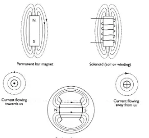
Magnetism can be created by a permanent magnet or by an electromagnet (it is one of the three effects of electricity remember). The space around a magnet in which the magnetic effect can be detected is called the magnetic field. The shape of magnetic fields in diagrams is represented by flux lines or lines of force. Some rules about magnetism:• Unlike poles attract. Like poles repel.
• Lines of force in the same direction repel sideways, in the opposite direction they attract.
• Current flowing in a conductor will set up a magnetic field around the conductor.
The strength of the magnetic field is determined by how much current is flowing.
• If a conductor is wound into a coil or solenoid, the resulting magnetism is the same as a permanent bar magnet.
Electromagnets are used in motors, relays and fuel injectors, to name just a few applications. Force on a current-carrying conductor in a magnetic field is caused because of two magnetic fields interacting. This is the basic principle of how a motor works. Figure 1.10 shows a representation of these magnetic fields.
Electrical and electronic principles
8
1.2.10 Electromagnetic induction
Basic laws:• When a conductor cuts or is cut by magnetism, a voltage is induced in the conductor.
• The direction of the induced voltage depends upon the direction of the magnetic field and the direction in which the field moves relative to the conductor.
• The voltage level is proportional to the rate at which the conductor cuts or is cut by the magnetism.
This effect of induction, meaning that voltage is made in the wire, is the basic principle of how generators such as the alternator on a car work. A generator is a machine that converts mechanical energy into electrical energy. Figure 1.11 shows a wire moving in a magnetic field.
1.2.11 Mutual induction
If two coils (known as the primary and secondary) are wound on to the same iron core then any change in magnetism of one coil will induce a voltage in to the other. This happens when a current to the primary coil is switched on and off. If the number of turns of wire on the secondary coil is more than the primary, a higher voltage can be produced. If the number of turns of wire on the secondary coil is less than the primary a lower voltage is obtained. This is called ‘transformer action’ and is the principle of the ignition coil. Figure 1.12 shows the principle of mutual induction. The value of this ‘mutually induced’ voltage depends on:
• The primary current.
• The turns ratio between primary and secondary coils. • The speed at which the magnetism changes.
1.2.12 Definitions and laws
Ohm’s law
• For most conductors, the current which will flow through them is directly proportional to the voltage applied to them.
The ratio of voltage to current is referred to as resistance. If this ratio remains constant over a wide range of voltages, the material is said to be ‘ohmic’.
V = I/R
where: I = Current in amps, V = Voltage in volts, R = Resistance in ohms.
Georg Simon Ohm was a German physicist, well known for his work on electrical currents.
Lenz’s law
• The emf induced in an electric circuit always acts in a direction so that the current it creates around the circuit will oppose the change in magnetic flux which caused it.
Lenz’s law gives the direction of the induced emf resulting from electromagnetic induction. The ‘opposing’ emf is often described as a ‘back emf’.
The law is named after the Estonian physicist Heinrich Lenz. Figure 1.11 Induction
Figure 1.12 Mutual induction
Definition
A generator is a machine that converts mechanical energy into electrical energy.
Key fact
Electrical and electronic principles
9
Kirchhoff’s laws
Kirchhoff’s 1st law:
• The current flowing into a junction in a circuit must equal the current flowing out of the junction.
This law is a direct result of the conservation of charge; no charge can be lost in the junction, so any charge that flows in must also flow out.
Kirchhoff’s 2nd law:
• For any closed loop path around a circuit the sum of the voltage gains and drops always equals zero.
This is effectively the same as the series circuit statement that the sum of all the voltage drops will always equal the supply voltage.
Gustav Robert Kirchhoff was a German physicist; he also discovered caesium and rubidium.
Faraday’s law
• Any change in the magnetic field around a coil of wire will cause an emf (voltage) to be induced in the coil.
It is important to note here that no matter how the change is produced, the voltage will be generated. In other words, the change could be produced by changing the magnetic field strength, moving the magnetic field towards or away from the coil, moving the coil in or out of the magnetic field, rotating the coil relative to the magnetic field and so on!
Michael Faraday was a British physicist and chemist, well known for his discoveries of electromagnetic induction and of the laws of electrolysis.
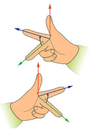
Fleming’s rules
• In an electrical machine, the First Finger lines up with the magnetic Field, the seCond finger lines up with the Current and the thuMb lines up with the Motion.
Fleming’s rules relate to the direction of the magnetic field, motion and current in electrical machines. The left hand is used for motors, and the right hand for generators (remember gener-righters).
The English physicist John Fleming devised these rules.
Ampère’s law
• For any closed loop path, the sum of the length elements times the magnetic field in the direction of the elements is equal to the permeability times the electric current enclosed in the loop.
In other words, the magnetic field around an electric current is proportional to the electric current which creates it and the electric field is proportional to the charge which creates it.
André Marie Ampère was a French scientist, known for his significant contributions to the study of electrodynamics.
Summary
It was tempting to conclude this section by stating some of Murphy’s laws, for example:
• If anything can go wrong, it will go wrong …
• You will always find something in the last place you look …
Electrical and electronic principles
10
• In a traffic jam, the lane on the motorway that you are not in always goes faster …
… but I decided against it!
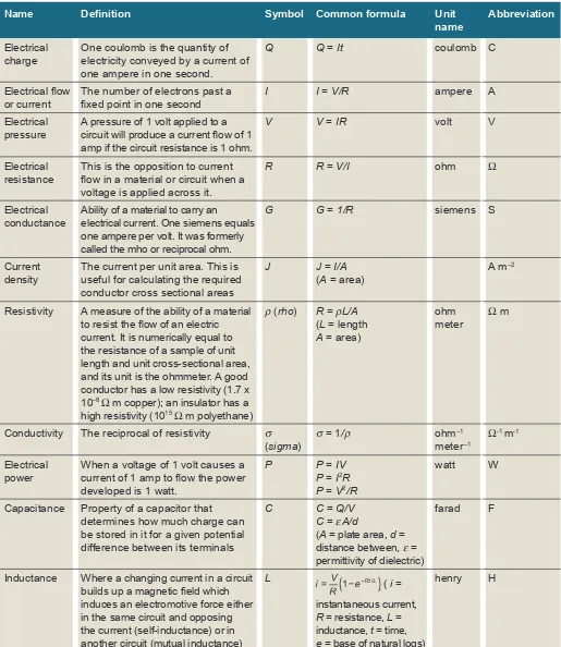
Table 1.2 Quantities, symbols and units
Name Definition Symbol Common formula Unit name
Abbreviation
Electrical charge
One coulomb is the quantity of electricity conveyed by a current of one ampere in one second.
Q Q = It coulomb C
Electrical flow or current
The number of electrons past a
fixed point in one second I I = V/R ampere A
Electrical pressure
A pressure of 1 volt applied to a circuit will produce a current flow of 1 amp if the circuit resistance is 1 ohm.
V V = IR volt V
Electrical resistance
This is the opposition to current flow in a material or circuit when a voltage is applied across it.
R R = V/I ohm Ω
Electrical conductance
Ability of a material to carry an
electrical current. One siemens equals one ampere per volt. It was formerly called the mho or reciprocal ohm.
G G = 1/R siemens S
Current density
The current per unit area. This is useful for calculating the required conductor cross sectional areas
J J = I/A
(A = area)
A m–2
Resistivity A measure of the ability of a material to resist the flow of an electric current. It is numerically equal to the resistance of a sample of unit length and unit cross-sectional area, and its unit is the ohmmeter. A good conductor has a low resistivity (1.7 x 10⁻⁸ Ω m copper); an insulator has a
high resistivity (1015Ω m polyethane)
ρ(rho) R = ρL/A
Conductivity The reciprocal of resistivity σ
(sigma) current of 1 amp to flow the power developed is 1 watt.
P P = IV P = I2R
P = V2/R
watt W
Capacitance Property of a capacitor that determines how much charge can be stored in it for a given potential difference between its terminals
Electrical and electronic principles
11
Table 1.2 (Continued)
Name Definition Symbol Common formula Unit name
Abbreviation
Magnetic field strength or intensity
Magnetic field strength is one of two ways that the intensity of a magnetic field can be expressed. A distinction is made between magnetic field strength H and magnetic flux density B. Magnetic flux A measure of the strength of a
magnetic field over a given area. Φ (phi) Φ(μ = = magnetic μHA
The density of magnetic flux, one tesla is equal to one weber per square metre. Also measured in Newton-metres per ampere (Nm/A)
1.3 Electronic components and circuits
1.3.1 Introduction
This section, describing the principles and applications of various electronic circuits, is not intended to explain their detailed operation. The intention is to describe briefly how the circuits work and, more importantly, how and where they may be utilized in vehicle applications.
The circuits described are examples of those used and many pure electronics books are available for further details. Overall, an understanding of basic electronic principles will help to show how electronic control units work, ranging from a simple interior light delay unit, to the most complicated engine management system.
1.3.2 Components
The main devices described here are often known as discrete components. Figure 1.14 shows the symbols used for constructing the circuits shown later in this section. A simple and brief description follows for many of the components shown.
Electrical and electronic principles
12
Figure 1.14
Electrical and electronic principles
13
For higher power applications, resistors are usually wire wound. This can, however, introduce inductance into a circuit. Variable forms of most resistors are available in either linear or logarithmic forms. The resistance of a circuit is its opposition to current flow.
A capacitor is a device for storing an electric charge. In its simple form it consists of two plates separated by an insulating material. One plate can have excess electrons compared to the other. On vehicles, its main uses are for reducing arcing across contacts and for radio interference suppression circuits as well as in electronic control units. Capacitors are described as two plates separated by a dielectric. The area of the plates A, the distance between them d, and the permittivity (ε), of the dielectric, determine the value of capacitance. This is modelled by the equation:
C = εA /d
Metal foil sheets insulated by a type of paper are often used to construct capacitors. The sheets are rolled up together inside a tin can. To achieve higher values of capacitance it is necessary to reduce the distance between the plates in order to keep the overall size of the device manageable. This is achieved by immersing one plate in an electrolyte to deposit a layer of oxide typically 104 mm thick, thus ensuring a higher capacitance value. The problem, however, is that this now makes the device polarity conscious and only able to withstand low voltages. Variable capacitors are available that are varied by changing either of the variables given in the previous equation. The unit of capacitance is the farad (F). A circuit has a capacitance of one farad (1 F) when the charge stored is one coulomb and the potential difference is 1 V. Figure 1.15 shows a capacitor charged up from a battery.
Diodes are often described as one-way valves and, for most applications, this is an acceptable description. A diode is a simple PN junction allowing electron flow from the N-type material (negatively biased) to the P-type material (positively biased). The materials are usually constructed from doped silicon. Diodes are not perfect devices and a voltage of about 0.6 V is required
Definition
Negative temperature coefficient
(NTC): As temperature
increases, resistance decreases.
Electrical and electronic principles
14
to switch the diode on in its forward biased direction. Zener diodes are very similar in operation, with the exception that they are designed to breakdown and conduct in the reverse direction at a pre-determined voltage. They can be thought of as a type of pressure relief valve.
Transistors are the devices that have allowed the development of today’s complex and small electronic systems. They replaced the thermal-type valves. The
transistor is used as either a solid-state switch or as an amplifier. Transistors are constructed from the same P- and N-type semiconductor materials as the diodes, and can be either made in NPN or PNP format. The three terminals are known as the base, collector and emitter. When the base is supplied with the correct bias the circuit between the collector and emitter will conduct. The base current can be of the order of 200 times less than the emitter current. The ratio of the current flowing through the base compared with the current through the emitter (Ie/Ib), is an
indication of the amplification factor of the device and is often given the symbol. Another type of transistor is the FET or field effect transistor. This device has higher input impedance than the bipolar type described above. FETs are constructed in their basic form as n-channel or p-channel devices. The three terminals are known as the gate, source and drain. The voltage on the gate terminal controls the conductance of the circuit between the drain and the source. A further and important development in transistor technology is the insulate gate bipolar transistor (IGBT). The insulated gate bipolar transistor (Figure 1.16) is a three-terminal power semiconductor device, noted for high efficiency and fast switching. It switches electric power in many modern appliances: electric cars, trains, variable speed refrigerators, air-conditioners and even stereo systems with switching amplifiers. Since it is designed to rapidly turn on and off, amplifiers that use it often synthesize complex waveforms with pulse width modulation and low-pass filters.
Inductors are most often used as part of an oscillator or amplifier circuit. In these applications, it is essential for the inductor to be stable and to be of reasonable size. The basic construction of an inductor is a coil of wire wound on a former. It is the magnetic effect of the changes in current flow that gives this device the properties of inductance. Inductance is a difficult property to control, particularly as the inductance value increases due to magnetic coupling with other devices. Enclosing the coil in a can will reduce this, but eddy currents are then induced in the can and this affects the overall inductance value. Iron cores are used to increase the inductance value as this changes the permeability of the core. However, this also allows for adjustable devices by moving the position of the core. This only allows the value to change by a few per cent but is useful for tuning a circuit. Inductors, particularly
Electrical and electronic principles
15
of higher values, are often known as chokes and may be used in DC circuits to smooth the voltage. The value of inductance is the henry (H). A circuit has an inductance of one henry (1 H) when a current, which is changing at one ampere per second, induces an electromotive force of one volt in it.
1.3.3 Integrated circuits
Integrated circuits (ICs) are constructed on a single slice of silicon often known as a substrate. In an IC, Some of the components mentioned previously can be combined to carry out various tasks such as switching, amplifying and logic functions. In fact, the components required for these circuits can be made directly on the slice of silicon. The great advantage of this is not just the size of the ICs but the speed at which they can be made to work due to the short distances between components. Switching speeds in excess of 1 MHz is typical. There are four main stages in the construction of an IC. The first of these is oxidization by exposing the silicon slice to an oxygen stream at a high temperature. The oxide formed is an excellent insulator. The next process is photo-etching where part of the oxide is removed. The silicon slice is covered in a material called a photoresist which, when exposed to light, becomes hard. It is now possible to imprint the oxidized silicon slice, which is covered with photoresist, by a pattern from a photographic transparency. The slice can now be washed in acid to etch back to the silicon those areas that were not protected by being exposed to light. The next stage is diffusion, where the slice is heated in an atmosphere of an impurity such as boron or phosphorus, which causes the exposed areas to become p- or n-type silicon. The final stage is epitaxy, which is the name given to crystal growth. New layers of silicon can be grown and doped to become n- or p-type as before. It is possible to form resistors in a similar way and small values of capacitance can be achieved. It is not possible to form any useful inductance on a chip. Figure 1.18 shows a representation of the ‘packages’ that integrated circuits are supplied in for use in electronic circuits. The range and types of integrated circuits now available are so extensive that a chip is available for almost any application. The integration level of chips has now reached, and in many cases is exceeding, that of VLSI (very large scale
Figure 1.17 Integrated circuit components
Electrical and electronic principles
16
integration). This means there can be more than 100 000 active elements on one chip. Development in this area is moving so fast that often the science of electronics is now concerned mostly with choosing the correct combination of chips, and discreet components are only used as final switching or power output stages.
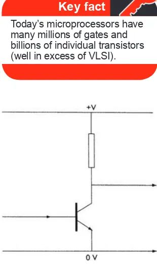
1.3.4 Amplifiers
The simplest form of amplifier involves just one resistor and one transistor, as shown in Figure 1.19. A small change of current on the input terminal will cause a similar change of current through the transistor and an amplified signal will be evident at the output terminal. Note, however, that the output will be inverted compared with the input. This very simple circuit has many applications when used more as a switch than an amplifier. For example, a very small current flowing to the input can be used to operate, say, a relay winding connected in place of the resistor. One of the main problems with this type of transistor amplifier is that the gain of a transistor (β) can be variable and non-linear. To overcome this, some type of feedback is used to make a circuit with more appropriate characteristics. Figure 1.20 shows a more practical AC amplifier.
Resistors Rb1 and Rb2 set the base voltage of the transistor and, because the base–emitter voltage is constant at 0.6 V, this in turn will set the emitter voltage. The standing current through the collector and emitter resistors (Rc and Re) is hence defined and the small signal changes at the input will be reflected in an amplified form at the output, albeit inverted. A reasonable approximation of the voltage gain of this circuit can be calculated as: Rc/Re. Capacitor C1 is used to prevent any change in DC bias at the base terminal and C2 is used to reduce the impedance of the emitter circuit. This ensures that Re does not affect the output.
Key fact
Today’s microprocessors have many millions of gates and billions of individual transistors (well in excess of VLSI).
Figure 1.19 Simple amplifier circuit
Output
Electrical and electronic principles
17
Output Output
Input V2 Input V1
–V +V
Figure 1.21 DC amplifier, long tail pair
For amplification of DC signals, a differential amplifier is often used. This amplifies the voltage difference between two input terminals. The circuit shown in Figure 1.21, known as the long tail pair, is used almost universally for DC amplifiers.
The transistors are chosen such that their characteristics are very similar. For discreet components, they are supplied attached to the same heat sink and, in integrated applications, the method of construction ensures stability. Changes in the input will affect the base–emitter voltage of each transistor in the same way, such that the current flowing through Re will remain constant. Any change in the temperature, for example, will affect both transistors in the same way and therefore the differential output voltage will remain unchanged. The important property of the differential amplifier is its ability to amplify the difference between two signals but not the signals themselves.
Integrated circuit differential amplifiers are very common, one of the most common being the 741 op-amp. This type of amplifier has a DC gain in the region of 100 000. Operational amplifiers are used in many applications and, in particular, can be used as signal amplifiers. A major role for this device is also to act as a buffer between a sensor and a load such as a display. The internal circuit of these types of device can be very complicated, but external connections and components can be kept to a minimum. It is not often that a gain of 100 000 is needed so, with simple connections of a few resistors, the characteristics of the op-amp can be changed to suit the application. Two forms of negative feedback are used to achieve an accurate and appropriate gain. These are shown in Figure 1.22 and are often referred to as shunt feedback and proportional feedback operational amplifier circuits.
The gain with shunt (parallel) feedback is: –R2/R1 The gain with proportional feedback is: R2/(R1 + R2)
Electrical and electronic principles
18
R2 Feedback resistor
R1
Op amp
Feedback Non-inverting
amplifier R1
R2
0 V 0 V
–V +V
+V
–V
Figure 1.22 Operational amplifier feedback circuits
Figure 1.23 Frequency response of a 741 amplifier
An important point to note with this type of amplifier is that its gain is dependent on frequency. This, of course, is only relevant when amplifying AC signals. Figure 1.23 shows the frequency response of a 741 amplifier. Op-amps are basic building blocks of many types of circuit, and some of these will be briefly mentioned later in this section.
Key fact
Operational amplifier gain is
Electrical and electronic principles
19
Figure 1.24 Wheatstone bridge
Figure 1.25 Bridge and amplifier circuit.
1.3.5 Bridge circuits
There are many types of bridge circuits but they are all based on the principle of the Wheatstone bridge, which is shown in Figure 1.24. The meter shown is a very sensitive galvanometer. A simple calculation will show that the meter will read zero when:
R1/R2 = R3/R4
To use a circuit of this type to measure an unknown resistance very accurately (R1), R3 and R4 are pre-set precision resistors and R2 is a precision
resistance box. The meter reads zero when the reading on the resistance box is equal to the unknown resistor. This simple principle can also be applied to AC circuits to determine unknown inductance and capacitance.
A bridge and amplifier circuit, which may be typical of a motor vehicle application, is shown in Figure 1.25. In this circuit R1 has been replaced by a temperature measurement thermistor. The output of the bridge is then amplified with a differential operational amplifier using shunt feedback to set the gain.
1.3.6 Schmitt trigger
Electrical and electronic principles
20
Figure 1.26 Schmitt trigger circuit utilizing an operational amplifier
fed into a Schmitt trigger will emerge as a square wave with the same frequency as the input signal. Figure 1.26 shows a simple Schmitt trigger circuit utilizing an operational amplifier.
The output of this circuit will be either saturated positive or saturated negative due to the high gain of the amplifier. The trigger points are defined as the upper and lower trigger points (UTP and LTP) respectively. The output signal from an inductive type distributor or a crank position sensor on a motor vehicle will need to be passed through a Schmitt trigger. This will ensure that either further processing is easier, or switching is positive. Schmitt triggers can be purchased as integrated circuits in their own right or as part of other ready-made applications.
1.3.7 Timers
In its simplest form, a timer can consist of two components, a resistor and a capacitor. When the capacitor is connected to a supply via the resistor, it is accepted that it will become fully charged in 5CR seconds, where R is the resistor value in ohms and C is the capacitor value in farads. The time constant of this circuit is CR, often-denoted τ.
The voltage across the capacitor (Vc), can be calculated as follows:
Vc = V(I – e–t/CR)
where: V = supply voltage; t = time in seconds; C = capacitor value in farads; R = resistor value in ohms; e = exponential function.
These two components with suitable values can be made to give almost any time delay, within reason, and to operate or switch off a circuit using a transistor. Figure 1.27 shows an example of a timer circuit using this technique.
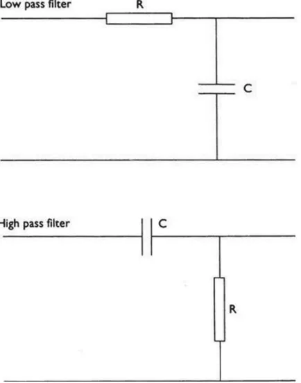
1.3.8 Filters
A filter that prevents large particles of contaminates reaching, for example, a fuel injector is an easy concept to grasp. In electronic circuits the basic idea is just the same except the particle size is the frequency of a signal. Electronic
Key fact
A Schmitt trigger is used to change variable signals square-wave type signals.
Definition
Electrical and electronic principles
21
Figure 1.27 Example of a timer circuit
Figure 1.28 Low pass and high pass filter circuits
filters come in two main types: a low pass filter, which blocks high frequencies, and a high pass filter, which blocks low frequencies.