• • • •
Steam Generators
and
Waste Heat Boilers
Steam Generators
Founding Editor L. L. Faulkner
Columbus Division, Battelle Memorial Institute and Department of Mechanical Engineering
The Ohio State University Columbus, Ohio
RECENTLY PUBLISHED TITLES
Steam Generators and Waste Heat Boilers: For Process and Plant Engineers V. Ganapathy
Maintenance, Replacement, and Reliability: Theory and Applications, Second Edition Andrew K.S. Jardine and Albert H.C. Tsang
Heat Exchanger Design Handbook, Second Edition, Kuppan Thulukkanam
Vehicle Dynamics, Stability, and Control, Second Edition, Dean Karnopp
HVAC Water Chillers and Cooling Towers: Fundamentals, Application, and Operation, Second Edition,
Herbert W. Stanford III
Ultrasonics: Fundamentals, Technologies, and Applications, Third Edition, Dale Ensminger and Leonard J. Bond
Mechanical Tolerance Stackup and Analysis, Second Edition, Bryan R. Fischer
Asset Management Excellence,
John D. Campbell, Andrew K. S. Jardine, and Joel McGlynn
Solid Fuels Combustion and Gasification: Modeling, Simulation, and Equipment Operations, Second Edition, Third Edition,
Marcio L. de Souza-Santos
Mechanical Vibration Analysis, Uncertainties, and Control, Third Edition, Haym Benaroya and Mark L. Nagurka
Principles of Biomechanics, Ronald L. Huston
Practical Stress Analysis in Engineering Design, Third Edition, Ronald L. Huston and Harold Josephs
Practical Guide to the Packaging of Electronics, Second Edition: Thermal and Mechanical Design and Analysis,
CRC Press is an imprint of the
Taylor & Francis Group, an informa business
Boca Raton London New York
Steam Generators
Boca Raton, FL 33487-2742
© 2015 by Taylor & Francis Group, LLC
CRC Press is an imprint of Taylor & Francis Group, an Informa business
No claim to original U.S. Government works Version Date: 20140331
International Standard Book Number-13: 978-1-4822-4714-5 (eBook - PDF)
This book contains information obtained from authentic and highly regarded sources. Reasonable efforts have been made to publish reliable data and information, but the author and publisher cannot assume responsibility for the valid-ity of all materials or the consequences of their use. The authors and publishers have attempted to trace the copyright holders of all material reproduced in this publication and apologize to copyright holders if permission to publish in this form has not been obtained. If any copyright material has not been acknowledged please write and let us know so we may rectify in any future reprint.
Except as permitted under U.S. Copyright Law, no part of this book may be reprinted, reproduced, transmitted, or uti-lized in any form by any electronic, mechanical, or other means, now known or hereafter invented, including photocopy-ing, microfilmphotocopy-ing, and recordphotocopy-ing, or in any information storage or retrieval system, without written permission from the publishers.
For permission to photocopy or use material electronically from this work, please access www.copyright.com (http:// www.copyright.com/) or contact the Copyright Clearance Center, Inc. (CCC), 222 Rosewood Drive, Danvers, MA 01923, 978-750-8400. CCC is a not-for-profit organization that provides licenses and registration for a variety of users. For organizations that have been granted a photocopy license by the CCC, a separate system of payment has been arranged.
Trademark Notice: Product or corporate names may be trademarks or registered trademarks, and are used only for identification and explanation without intent to infringe.
vii
Preface ... xiii
Author ... xxxi
1. Combustion Calculations ...1
Introduction ...1
Moisture in Air ...1
Combustion Calculations ...2
Excess Air from Flue Gas Analysis ...8
Simplified Combustion Calculations ... 10
Estimation of Heating Values ... 12
Burner Selection ... 13
Combustion Temperatures ... 14
Simplified Procedure for Estimating Combustion Temperatures ... 15
Effect of FGR on Combustion Temperature ... 15
Relating FGR and Oxygen in Windbox ... 16
Gas Turbine Exhaust Combustion Calculations ... 17
Relating Oxygen and Energy Input in Turbine Exhaust Gases ... 17
Evaluating Fuel Quantity Required to Raise Turbine Exhaust Gas Temperature ...19
Firing Temperature versus Oxygen, Burner Duty, and Water Vapor ... 21
Boiler Efficiency ... 21
Heat Loss Method ...22
Simplified Formulae for Boiler Efficiency ...23
Simplified Procedure for Obtaining Major Boiler Parameters ... 26
Excess Air versus Efficiency ... 26
Firing Fuels with Low Heating Values ...27
Firing of Multiple Fuels ...29
Emission Conversion Calculations: Steam Generators ... 29
Converting ppmvd of NOx to mg/Nm3 ... 32
Converting Turbine Exhaust Emissions ...34
Low-Temperature Corrosion in Boilers ...35
Condensation of Acid Vapors in Low-Temperature Heat Sinks ...38
Acid Dew Point Temperature Tdp ...38
References ...40
2. Steam Generator Furnace Design ... 41
Advantages of Water-Cooled Furnaces ...43
Ring Header Design ...44
Heat Release Rates ...46
Steam Pressure ...47
Circulation Systems ... 52
Furnace Exit Gas Temperature Evaluation ...53
Furnace Duty with Combination Firing ...60
Distribution of Heat Flux around Tubes and Fins ... 61
Distribution of Radiation to Tube Banks ... 61
Relating Heat Flux from Furnace to inside Tubes ...64
External Radiation to Heat Transfer Surfaces at Furnace Exit ...65
Direct Radiation to Superheater at Part Load ...66
Terms Frequently Used in Furnace Performance... 67
Estimating Boiling Heat Transfer Coefficient ... 67
Estimating Fin Tip Temperature ...68
Boiling Process ... 69
Boiler Circulation ... 70
Thom’s Method for Estimating Losses ...75
Circulation Calculations ...77
Circulation Flow versus Load ... 81
Flow Stratification in Horizontal Tubes ... 82
Correlations for CHF (Critical Heat Flux) and Allowable Steam Quality ... 82
Circulation Problems ...85
Guidelines for Good Circulation System Design ...85
References ...86
3. Steam Generators ... 87
Introduction ... 87
Large Package Boilers ... 87
Water-Cooled Furnaces ...90
Major Changes in Boiler Design ...90
Absence of Air Heater ...90
Emissions Affect Steam Generator Designs ...92
Custom-Designed Boilers ...97
Novel Ideas ...97
O-Type Package Boiler ...98
Dual-Pressure Design ...99
Small Changes, Big Benefits ...99
Boiler Classification ... 103
Improving Boiler Efficiency ... 108
Adding Condensate Heater to Improve Boiler Plant Efficiency ... 109
Understanding Boiler Performance ... 111
Why Economizer Does Not Steam in Steam Generators ... 112
Understanding Boiler Surface Areas ... 113
Steam Generators for Oil Sands Application ... 115
Superheaters ... 118
Radiant versus Convective Superheaters ... 121
How Emissions Impact Radiant and Convective Superheaters ... 124
Arrangement of Superheaters ... 124
Steam Temperature Control ...125
Steam Generators with Import and Export Steam ... 129
Flow in Parallel Paths ... 129
Steam Inlet and Exit Nozzle Location ... 130
Case Study of a Superheater with Tube Failure Problems ... 135
Problem at Low Loads with Inverted-Loop Superheaters ... 137
Steam Generator Design and Performance ... 138
Data Required for Performing Steam Generator Analysis ... 139
Checking Boiler Performance ... 142
Evaluating Part Load Performance ... 146
Performance without Economizer ... 149
Tube Wall Temperature Estimation at Economizer Inlet ... 149
Methods to Minimize Low-Temperature Corrosion Problems ... 151
Precautions to Minimize Corrosion in Operation ... 154
Water Chemistry, Carryover, Steam Purity ... 155
Fire Tube Boilers ... 157
Boiler Horse Power ... 160
Sizing and Performance Calculations ... 160
References ... 163
4. Waste Heat Boilers ... 165
Introduction ... 165
Gas Inlet Temperature and Analysis... 168
Flue Gas Composition and Gas Pressure ... 170
Water Tube versus Fire Tube Boilers ... 173
Circulation Systems ... 174
Heat Recovery in Sulfur Plants ... 178
Heat Recovery in Sulfuric Acid Plant ... 181
Heat Recovery in Hydrogen Plants ... 182
Combining Solar Energy with Heat Recovery Systems ... 184
Gas Turbine HRSGs ... 184
Natural, Forced Circulation, Once-Through Designs, and Special Applications ...188
Natural versus Forced Circulation HRSGs ... 191
Emission Control in HRSGs ... 194
Flow-Accelerated Corrosion ... 195
Water Tube Waste Heat Boilers: Sizing and Performance ... 197
Optimizing Pinch and Approach Points in HRSGs ... 197
HRSG Performance and Evaluating Field Data ... 199
Efficiency of Waste Heat Boiler, HRSG ...204
Advantages of Supplementary Firing in HRSGs ...204
HRSG and Steam Generator Performance ...205
Optimum Utilization of Boilers ... 205
Combined Cycle Plants and Fired HRSGs ...206
HRSGs with Split Superheaters ...208
Performance with and without Export Steam ...208
Providing Margins on Heating Surfaces ... 217
Cement Plant Waste Heat Recovery ... 217
Kalina Cycle ...223
Advantages of Kalina Cycle ... 224
Fluid Heaters and Film Temperature ...227
Design of Fire Tube Boilers ...230
Effect of Scale Formation ...234
Estimation of Loss in Performance Due to Fouling ...236
Tube Wall Thickness Calculations ...236
Off-Design Performance with Addition of Economizer ...238
Simulation of Fire Tube Boiler Performance ... 239
Effect of Gas Analysis on Performance... 241
Critical Heat Flux qc ... 242
Effect of Tube Size on Boiler Design ...244
Estimating Tube Bundle Diameter ... 245
Simplified Approach to Evaluating Performance of Fire Tube Boilers ... 245
Estimating Tube Sheet Thickness ... 248
Estimating Tube Sheet Temperature with Refractory and Ferrules ... 248
Calculation of Tube Sheet Temperature without Refractory on Tube Sheet ... 249
Air Heaters ...250
Heat Pipes ... 251
Design of Tubular Air Heaters ... 252
Heat Transfer Inside and Outside Tubes ...253
Part Load Performance ... 257
Specifying Waste Heat Boilers ...258
Waste Heat Boiler Data (Thermal Design) ...259
References ... 261
5. HRSG Simulation ... 263
Introduction ... 263
What Is HRSG Simulation? ...263
Applications of HRSG Simulation ...265
Understanding Pinch and Approach Points ...266
Estimating Steam Generation and Gas–Steam Temperature Profiles ... 267
Why Cannot We Arbitrarily Select the Pinch and Approach Points? ... 270
Why Should Pinch and Approach Points Be Selected in Unfired Mode? ... 271
Simulation of HRSG Evaporator ...272
Supplementary Firing ... 273
Off-Design Performance Evaluation ... 274
How Accurate Is Simulation? ... 279
Steaming in Economizer ... 281
Methods to Minimize Steaming in Economizer ...283
Field Data Evaluation ...284
Single- or Multiple-Pressure HRSG ...286
Split Superheater Design ... 295
Fresh Air Firing ...299
Efficiency of HRSG ...300
Cogeneration Plant Application ... 301
Optimizing HRSG Arrangement ...303
Application of Simulation to Understand the Effect of Ambient Conditions ...305
Applying Margins on Exhaust Gas Flow and Temperature ...306
Conclusion ...308
6. Miscellaneous Boiler Calculations ...309
Condensing Economizers ...309
Water Dew Point of Flue Gases ... 310
Energy Recoverable through Condensation ... 311
Condensation Heat Transfer Calculations... 312
Condensation over Finned Tubes ... 315
Wall Temperature of Uninsulated Duct, Stack ... 317
Insulation Calculations ... 320
Hot Casing Design ...322
Drum Coil Heater: Bath Heater Sizing ... 323
Checking Heat Transfer Equipment for Noise and Vibration Problems ... 327
Determining Natural Frequency of Vibration of Tubes ... 327
Acoustic Frequency fa ... 328
Vortex Shedding Frequency fe ... 328
Damping Criterion ... 331
Fluid Elastic Instability ... 332
Steam Drum Calculations ...333
Steam Velocity in Drum ...333
Blowdown Calculations ...335
Drum Holdup Calculations ...339
Estimating Flow in Blowdown Lines ...340
Theory ...340
Flow Instability in Two-Phase Circuits ...343
Transient Calculations ...346
Analysis of an Evaporator ...348
Drum-Level Fluctuations ...350
Fan Calculations ... 351
Density of Flue Gas, Air ... 351
Pressure Drop in Ducts ... 352
Fan Selection ...353
Why Should the Fan Capacity Be Reviewed at the Lowest Density Condition? ... 354
Head Developed by Fan ...355
Fan Power Consumption...355
Estimating Stack Effect ...355
References ...356
Appendix A: Boiler Design and Performance Calculations ... 357
Appendix B: Tube-Side Heat Transfer Coefficients and Pressure Drop ...377
Appendix C: Heat Transfer Coefficients Outside Plain Tubes ... 393
Appendix D: Nonluminous Heat Transfer Calculations ...407
Appendix E: Calculations with Finned Tubes ... 413
Appendix F: Properties of Gases ...447
Conversion Factors...485
Glossary ... 491
xiii For over three decades, I was associated with boiler companies designing oil- and gas-fired custom package boilers and waste heat boilers that are in operation worldwide in chemical plants, refineries, cogeneration systems, and power plants. The boilers have been operating well and performing as predicted within the margin of measurement errors. As a spe-cialist in thermal design of heat transfer equipment and out of interest, I would correlate field data from operating units with predicted performance to check the correction factors to be incorporated in heat transfer or gas pressure drop correlations that were used for designing the boilers. I would review operating data such as boiler exit gas temperature, steam generation, fuel input, gas pressure drop, evaporator, superheater performance, their tube wall temperatures, and other process-related parameters and compare the results with predicted data. Over the years this has helped me to fine-tune the calculation procedure and modify the correction factors used in the performance evaluation of vari-ous heat transfer surfaces. Through the publication of hundreds of articles during this period, I have also been sharing thermal design procedures for boilers and HRSGs with the engineering community. I have written a few books, the recent being Industrial Boilers and HRSGs, where the emphasis was on sizing and performance evaluation of steam
gen-erator and waste heat boiler components.
For the past decade, since the publication of the cited book, I have been playing the role of a boiler consultant. The transformation from a boiler designer to a boiler consultant has been gratifying as I can interact with plant engineers worldwide and learn from them about various boiler performance issues and suggest modifications to solve boiler-related prob-lems or improve their performance (the word boiler refers to a steam generator as well as a
waste heat recovery unit). Many plant engineers or even consultants have no clue as to how a boiler should be evaluated before it is bought or what information should be obtained from boiler suppliers regarding its thermal performance aspects. They rely entirely on the sales pitch from boiler suppliers and buy it without giving any critical thought to its design from a thermal performance viewpoint. Purchasing a boiler is thought of as purchasing a commodity. When purchasing a steam generator or HRSG, plant engineers have to evalu-ate several factors keeping in mind that the life of a boiler is about 30 to 40 years and that the plant will have to face the consequence of any wrong decision for a long time. Some of the considerations are
• Is the consultant engaged by the plant well versed in thermal or process engineer-ing aspects?
• Is the boiler design reflecting the latest trends and improvements in technology? • How can one rationalize the differences in surface areas among various proposals
for the same boiler? Selecting the boiler with the maximum surface area is not the answer.
• Can the boiler handle future emission regulations on NOx, CO, or UHC with
mini-mum field modifications?
• Have provisions been made to deal with sulfuric acid dew point corrosion in heat-ing surfaces while firheat-ing high-sulfur fuels or handlheat-ing flue gas containheat-ing SO2 and
SO3?
• While firing fuels containing ash or low-melting point solids, can the boiler front end withstand potential slagging and high-temperature corrosion?
• Has the HRSG supplier evaluated the economics of pinch point and approach point while arriving at the HRSG size and steam generation?
• Has the boiler supplier considered all heat sinks available in the plant and tried to maximize energy recovery? The plant engineer has a major role to play in this matter.
• Why is a dual-pressure HRSG offered? Can a single-pressure HRSG not do the same job?
• Why surface areas in finned heating surfaces vary so much between HRSG designs, and how to rationalize difference?
• Significance of heat flux in steam generators and its relation to circulation. • Relation between superheater tube wall temperature and reduction in its life. • Is the steam-side pressure drop reasonable at the design point considering all
operating loads?
• Advantages of a given design over another, say insulated/refractory lined fur-nace wall over membrane wall furfur-nace design or a convective superheater versus a radiant design in steam generator.
• Has the performance data at various loads and with different fuels been provided? • Has complete geometric data of the boiler heating surfaces such as furnace, super-heater, evaporator, economizer, and air heater been provided so that an indepen-dent evaluation of performance can be done before the boiler is purchased? Many boiler suppliers do not provide this information, and many plant engineers do not know that they should have this important data.
• Will the Kalina cycle be a better choice for their low-gas temperature heat recovery application rather than a steam system?
• Have design features to minimize the boiler or HRSG startup time been provided?
If issues such as those mentioned are not discussed or reviewed before the boiler is pur-chased, many problems related to thermal performance can surface during operation later on; these include issues such as
• Steam generation much lower than predicted (HRSGs and waste heat boilers) • Superheater tube failure or overheating and sagging of tubes
• Steam temperature not achieved at rated load
• Flow stagnation in superheater tubes due to low-friction loss and high-gravity loss at low loads
• Too much spray water than envisaged while controlling steam temperature • Circulation problems resulting in evaporator tube failures
• Fuel consumption in supplementary fired burners higher than expected or pre-dicted or higher firing temperature in HRSGs than prepre-dicted
• Longer startup time than predicted
• Operating costs too high and not envisaged
Plants also have to face several issues regarding boiler thermal performance:
• Unsure whether fouling on steam side or improper design caused tube overheating. • Unsure whether fouling on gas or steam side caused lower steam output.
• Inability to understand the performance characteristics of steam generator and HRSG versus load and how to optimally load them to maximize plant steam gen-eration and minimize fuel input.
• If operating parameters of a HRSG such as steam generation and exit gas tem-perature are different from those in the proposal, how to determine if it is due to variations in gas inlet conditions or if it is due to improper sizing of the boiler? • If a steam generator is operating at say 70% capacity for which performance data
such as efficiency or steam temperature or exit gas temperature was not provided by the boiler supplier, how does one find out if it is operating as it should?
When the plant engineer brings the operating problems to the attention of the boiler sup-pliers, naturally they defend their design and extraneous reasons are blamed for the prob-lems. In my experience not many plant engineers have been familiar with heat transfer and thermal performance aspects, and as a result accept any report from boiler suppliers and as such, are unable to challenge the findings with calculations or studies they have done independently, at the same thing realizing that the design is really flawed. With numerous real world examples on steam generator and HRSG design and off-design performance aspects and calculation modules for major boiler components such as superheater, evapo-rator, air heater, economizer, and furnace (unfired and fired) given in this book, any plant or process engineer should be able to improve his knowledge in this field and become a competent thermal engineer or consultant and be able to question the boiler supplier if a compromised design is offered and correct the deficiencies before it is manufactured and not after the boiler is installed.
the other way around; they can evaluate the off-design performance of a complete HRSG at any gas inlet condition or check the superheater tube wall temperature or its duty based on the geometric data provided, or an evaporator design considering the circulation sys-tem proposed, or check the fuel guarantees offered by boiler suppliers for steam genera-tors or HRSGs. For off-design performance calculations, two methods have been provided and illustrated through several examples. Plant engineers can simulate the performance of their operating boilers and perform what if analysis and gather more information about existing units. The adage that knowledge is power is true in any field of endeavor and applies equally to the field of boiler design and performance evaluation. The problems that many plants face today with boilers and waste heat recovery systems are mainly due to the fact that the designs are accepted as such without being critically evaluated before they are purchased. If the plants do not have the resource to perform this evaluation, they may hire an independent consultant to do so. Remember that a plant has to use a boiler for over 30 or 40 yearsand time and money spent in the evaluation (before the boiler is purchased!) will pay dividends later in the form of low maintenance or repair costs or problem-free operation. When problems such as tube failures, overheating of tubes, lack of performance, and lower than predicted efficiency surface after a few months of operation, the boiler sup-plier always defends his design, and if the plant does not have knowledgeable thermal or process engineers to counter the supplier’s claims with appropriate calculations and stud-ies, the problems may never be fixed or resolved. I have seen some boilers, in some plants, which should have never been bought as supplied, because the plants spend a lot of time in shutdowns, repairs, and are unable to operate the boiler at the rated capacity.
engineers to design the boiler, or passed on the drawings of a similar boiler designed years ago without checking the suitability for the present situation, the plant engineer may not be aware that the boiler has very high operating costs, or the customer may not have provided all the information regarding plant parameters or their requirements for future operation such as changes in steam parameters or fuel data. Note that plant engi-neers have to be more cautious and responsible than boiler suppliers or their consultants before purchasing the boiler as they have to use the unit for 30 to 40 years, while for the consultants or boiler suppliers it is just one more boiler and they move on to other projects once the boiler or HRSG has been sold! Hiring a consultant who specializes in process heat transfer or thermal engineering can help a plant foresee problems in their boiler before it is purchased and save them a lot of money in the long run. Alternatively, plants should develop a team of in-house engineers who specialize only in boiler-related process calcula-tions and who can check the design offered by the boiler supplier; the purpose of this book is exactly that, namely, to educate plant engineers and consultants in thermal design and performance calculations. Many reputable boiler suppliers while making a sales pitch say that they have thousands of such boilers and similar designs in operation and yet within a few months of operation, several problems cited earlier surface and the plant engineers run from pillar to post to fix the issues or they may never be fixed as the design modifica-tion would be as expensive as replacing the unit!
When I was a boiler designer in the United States, custom-designed boilers were offered by my company as these have several advantages, as discussed in Chapter 3, over standard or off-the-shelf designs. Standard or off-the-shelf boilers are predesigned for a particular steam output with tube geometry, tube spacing, height, width, length all fixed. In fact, they may have already been built and branded as, for example, 40 t/h or 70 t/h boilers. Note that the efficiency, steam temperature, gas pressure drop through the boiler, or fan power consumption is dependent on the quantity of flue gas flowing through the boiler. As explained in Chapter 3, with the introduction of flue gas recirculation (FGR) for NOx
control, one has to check the boiler performance based on actual flue gas flowing through the unit and not select a boiler from a catalog based on steam capacity. Local conditions such as site elevation and ambient temperature may also affect performance. A few plant engineers even today order a water tube boiler based on the model number. While such an approach may save time and money, it is suitable wherever emission regulations need not be complied with or when saturated steam is generated or when clean, standard fuels are fired. When the boiler has to comply with emission regulations or when special fuels are fired, about 15% excess air and 15%–30% FGR may have to be used depending on the NOx
not a standard model; he was questioning why our forced draft fan was smaller than that of the competition! He had also come to the conclusion that our fan will not work! I had to then explain to him about custom designing of boilers and the advantages accrued to its owner over a period of time and how our tube spacing and tube lengths were adjusted on a case-by-case basis to lower the gas pressure drop and maintain the efficiency consider-ing the higher flue gas flow through the boiler arisconsider-ing out of local NOx and CO regulations!
Many large boiler suppliers do not want to change the boiler design or dimensions on a case-by-case basis as it is expensive, while a small boiler company can make these changes easily as this does not need approval from the corporate office.
To give another example, many plants even today purchase boilers or HRSGs based on surface area, which is a big mistake! Engineers tabulate surface areas offered by dif-ferent vendors and if the prices are comparable, select the vendor with the largest sur-face area, and to add insult to injury, the customer thinks he is getting a bargain! As explained in Appendix E, surface area of a finned tube superheater or evaporator in a HRSG can vary by about 50%–100% for the same duty depending on the fin geometry chosen. Higher fin density leads to higher heat flux inside the superheater tubes, resulting in higher tube wall temperatures and shortened superheater life. Higher fin density also results in a lower overall heat transfer coefficient, necessitating a larger surface area for the same duty and higher gas pressure drop. The customer was under the impression that our superheater was too small as the surface area with our small fin density was about 60%–70% of that of the competition and hence would not achieve the steam temperature. Fortunately, the customer called and asked me this question and I sent him copies of the articles I had published on finned tubes explaining how the U values decrease with an increase in ratio of external to tube internal surface and the product of U × A (overall heat transfer coefficient × surface area) was the important thing to check and not A alone. (The problem is many boiler vendors will not provide information on U values but just the sur-face area, and unsuspecting engineers may evaluate the options based on sursur-face area alone.) I explained to him about the increase in heat flux caused by poor selection of fins and how the tube wall temperature would increase and as a result how tube life would decrease. After this presentation, they were convinced and appreciated the importance of proper selection of fins in HRSGs. Plant engineers who are not process savvy will jump at the offer with the highest surface area and may have to deal with issues such as high heat flux inside tubes or overheating of tubes later! The book gives a few examples of the effect of fin geometry on the overall heat transfer coefficient and tube wall temperature in the evaporator and superheater so that plant engineers or consultants are not mislead by surface areas when buying a HRSG. Bottom line is “Don’t go by surface area A alone. Ask for the U (overall heat transfer coefficient) for each heating surface!” Then check U × A, which should be the same for all vendors for any component with the same duty. The appendices also provide methods to evaluate heat transfer coefficients inside and outside plain and finned tubes so that U may be estimated independently for each heating surface and checked with data provided by the boiler vendor. There may be some differences in U values between boiler suppliers, but they should be small.
pressure, which may be slightly more expensive but pay dividends in the long run in the form of lower operating costs and fuel consumption if the HRSG is fired. Methods to improve the efficiency of a steam generator or HRSG using secondary heating surfaces or by lowering the feed water temperature or by heating air using a closed loop glycol system are discussed.
When fuels with potential for acid dew point corrosion are fired in steam generators, some consultants suggest that the exit gas temperature be raised above the dew point. However, this does not prevent acid vapor condensing at the feed water inlet section of the economizer tubes, which may be operating below the acid dew point temperature. In fact, the temperature of the feed water should be raised to avoid condensation and consequent local corrosion and not the gas temperature alone as the tube side heat transfer coefficient is much higher than the gas side coefficient and hence governs the tube wall tempera-ture. Raising the gas temperature above the dew point may prevent corrosion in the ducts downstream of the economizer but not in the tubes per se. One should also understand the fact that as the steam generator load decreases, the economizer exit gas temperature will also decrease and the ducts also can get corroded at part loads. This can be prevented by ensuring that the feed water temperature is above the acid dew point as discussed in Chapter 3, as a result of which the exit gas temperature will always be above the dew point at all loads! The book also discusses the option of using condensing economizers and its sizing procedure and evaluation of additional energy recovery and materials to be used in such applications. The importance of keeping a boiler warm during startup and shutdown while using sulfur-containing gases in boilers and HRSGs is also stressed. Examples show how one may estimate the cold end tube wall temperature in the air heater and econo-mizer and also the effect of the counter flow versus parallel flow arrangement on cold end tube temperature with plain and finned tubes.
When specifying gas turbine HRSGs, consultants not familiar with process calculations or HRSG temperature profile analysis expect a certain exit gas temperature from the boiler or a certain amount of steam generation in the unfired mode. This may not be always attainable as the gas–steam temperature profile is dependent on the pinch and approach points chosen and the steam pressure and this is a thermodynamic limitation. The higher the steam pressure, the higher the exit gas temperature unless one adds a low-pressure steam system. Thus, one cannot predict a particular exit gas temperature without doing an analysis of temperature profiles. Also, many plant engineers are not aware of the fact that supplementary firing is the most efficient way of generating additional steam in a HRSG. If a refinery has both steam generators as well as gas turbine HRSGs, it is prudent to plan future HRSGs as fired units so that steam can be generated at more than 100% efficiency compared with about 93% (on lower heating value basis) in steam generators for gas firing. This point is explained in Chapter 5 on HRSG simulation. The cost of a HRSG is mainly a function of the exhaust gas flow through it, and since this remains the same whether the HRSG is unfired or fired, planning the HRSG for firing in the future is a good idea as the additional cost of burners and insulation will be minimal. On the other hand, the plant can obtain 100%–300% more steam through supplementary firing or furnace-fired HRSGs.
Dual-pressure HRSGs are not required for all cases involving HP and LP steam require-ment. The ratio of LP steam flow to HP steam and the ratio of LP steam pressure to HP steam pressure impact the temperature profile, and sometimes it is more prudent to go with a single-pressure HRSG and take off the process steam from the drum and pressure-reduce it rather than install a dual-pressure HRSG that could be more expensive than a single-pressure unit as shown in Chapter 5. Unless the plant engineer or the consultant is familiar with such analysis, a dual-pressure HRSG may be specified by the plant or the consultant without any analysis, which can be expensive in the long run. It is my desire that a consultant or a plant engineer review any boiler or HRSG design offered to a plant and independently check if there is scope for improving the energy recovery.
Often HRSGs operate in the fired and unfired mode. Common practice is to locate the superheater downstream of the burner and design the superheater in a way that steam temperature is obtained in the unfired mode and then the stream is desuperheated in the fired mode to obtain the desired steam temperature using demineralized water spray. This design is not expensive as the superheaters are built as a single module. This approach, however, may increase the tube wall temperature of the superheaters in the fired mode; also some plants may not have demineralized water for attemperation. One novel approach discussed in the book is to split the superheater so that the final superheater is located beyond the gas turbine and the primary superheater is located downstream of the burner. This approach also lowers the tube wall temperature of the superheaters and eliminates the need for spray attemperation in many cases.
Low-temperature heat recovery as in cement plants offers many challenges. If steam is used as the working fluid, pinch point limits the heat recovery potential as the lower the inlet gas temperature, the higher the exit gas temperature unless there is multiple pressure steam generation. (The reason for this is explained in Chapter 5.) The Kalina cycle HRVG discussed in the book enables the exit gas temperature from the HRVG to be much lower than possible with steam systems due to the varying boiling point of the ammonia–water mixture working fluid. Gas inlet temperatures of 250°C–350°C are ideal heat sources for the Kalina cycle.
There are applications where space is a premium. In one project, a plant had to fit a steam generator of 50 t/h capacity inside a building of width 3.5 m. For example, in Chapter 3, a steam generator with a width of about 3 m is shown with finned tubes in the convection section. A conventional A- or D- or O-type boiler design would not have fitted into this space as its width would have exceeded 5 m and considering space around the boiler, it would have been impossible for a regular or conventional boiler to be installed. As a boiler designer, I came up with an idea of using a O-type boiler with finned tubes with a width of less than 3 m; to reduce the total boiler length, finned tubes were used in the convection bank. The plant engineers and consultants involved in the project appreciated what we were offering and hence the project was a success. If the plant engineers had not been open to this idea, they may have been without a boiler or destroyed the building and installed a standard boiler! It was explained to the plant personnel that finned tubes are used in HRSGs and the boiler offered simply borrowed that concept though it was the first time this was done in a steam generator!
and purchase of this boiler, it was not difficult to sell the idea. Hence, it is important that engineers with a background in thermal design or process calculations are also involved in the purchasing decisions of a plant.
In package oil- and gas-fired steam generators, many boiler vendors offer a radiant super-heater even if the steam temperature required is only about 350°C–400°C. It is possible to attain about 500°C with a convective superheater, which has fewer tube failures or perfor-mance problems compared with the radiant design. The radiant superheater is more prone to failures at full as well as part loads compared with the convective design, as discussed in Chapter 3. Another common problem is that the flame may impinge on the superheater if the burner is not properly adjusted and there is always a dispute whether the burner is causing the tube failures or if the design of the superheater itself is flawed. Another error made by some consultants is to specify that the steam pressure drop in the superheater should be low; I have seen figures as low as 0.35 kg/cm2 (5 psi) at full load. This is a very
low value for a good design, particularly if the degree of superheat is large and the boiler has to operate over a wide range of steam flows. One has to review the steam velocity, the tube wall temperature, and the pressure drop at all loads. As a designer, I used to ask them about the flow distribution issues at lower loads with such a low pressure drop to start with. At 50% load, the pressure drop will be less than 0.1 kg/cm2, leading to flow stagnation or
reverse flow in some tubes with downward flow where the gravity head opposes the friction loss; hence, overheating or failure can occur if the gas temperature is high. The importance of tube side pressure drop in superheater and the significance of low flow in upward and downward paths are discussed in Chapter 3. Lack of understanding of process or thermal design is the reason for such ridiculous specifications. Also, if the superheater fails because of the low pressure drop suggested by the consultant, then who is at fault?
Some consultants while evaluating offers from different boiler suppliers do not even obtain the thermal or tube geometry data for the boiler surfaces, which is required to do a performance evaluation at a later date if need arises. The plant engineers feel that the consultant who has prepared the specifications will do a good job and do not interfere with the evaluation process. The consulting company may or may not have thermal or process engineers on their team. If they do not, then the plant may have to be at the mercy of the boiler supplier when a boiler problem arises later on, when they do not even have the minimum information to be able to evaluate the boiler’s performance. As a boiler consultant, I have seen this problem in many plants and hence one of the services I provide is to evaluate boilers from thermal and performance viewpoints and ensure that all tube geometry data for steam generators and HRSGs are made available by the supplier before purchase. Chapters 3 and 4 present several examples of the format of the tube geometry data. Plant and process engineers should ensure that suppliers of boilers for steam generators and HRSGs provide information in this format so that future per-formance evaluation becomes easy. Presently many boiler suppliers get away with very sketchy information on their boiler tube geometry and performance details. Only when a problem arises in the boiler and the performance has to be checked do plant engineers run around looking for basic information about the boiler. The boiler supplier may not even be around when these data are required!
Many plant engineers are not aware of the differences in boiler efficiencies based on higher and lower heating values. It is the practice in the United States to state boiler ciency on an HHV basis, whereas in Europe and Asia, it is based on LHV. The LHV effi-ciency is higher by a factor equal to the ratio of higher to lower heating value of the fuel. Hence, unless the basis of efficiency is mentioned, clearly evaluation can be skewed. Also, while specifying waste heat boilers, consultants sometimes provide the volumetric gas flow instead of mass flow. This practice should be avoided. One should provide the flue gas flow in mass units such as kg/h and the flue gas analysis as the gas properties and duty are affected by the gas analysis. Energy balance is done using mass of flue gas and not its volume. Variation in steam output can be even 5% or more if some boiler vendor assumes an analysis based on his experience while another vendor assumes a different gas analysis and computes the density. I have seen n different answers from n engineers for the density of flue gas at a given pressure and temperature!
Often performance information on steam generator or HRSG is not completely provided by the boiler supplier when a boiler is sold; little technical or process information is offered during the contract stage, but shrewd plant engineers should ask the boiler supplier to furnish more information on thermal performance such as part load performance and what happens if some steam parameters change such as steam pressure or feed water temperature or fuel analysis. Some plants may operate at say 25% load for most of the time and then go on to 100% load. The plant may need the specified steam temperature at 25% load also, which may not have been discussed. Once the boiler is started up and if it is found that the steam temperature is much lower, the boiler supplier cannot be blamed. Sometimes, a low BTU fuel may be fired after a few years of installation. This will increase the flue gas flow through the boiler and also affect the furnace absorption, steam tem-perature, backpressure, and efficiency. This scenario must be discussed with the boiler supplier before the boiler is purchased. The plant can make a decision whether to buy the larger fan now or later, when they switch to the low Btu fuel firing mode.
A steam plant was planning a large, new waste heat boiler; it was generating saturated steam in another waste heat boiler and wanted to superheat the saturated steam in the new boiler. This type of design calls for a large superheater and one has to see what happens to the steam temperature and the tube wall temperature when the import steam is absent. A large amount of spray would also be required to control the steam if import steam is absent. The superheater has to be designed considering both the cases. Refineries often encounter such situations as they have numerous process streams generating saturated steam and they would like to superheat this in another new boiler whether it is a steam generator or waste heat boiler. Separately fired superheaters may be inefficient and prone to problems pared with convective-type superheaters in steam generators. In solar plants that are com-bined with waste heat boilers or HRSGs, the saturated steam from the solar panels must be superheated in the waste heat boiler. Even when the solar panel does not generate steam, the superheater of the waste heat boiler should operate safely without overheating the tubes.
Often gas turbine HRSGs and waste heat boilers are designed for a particular gas inlet flow and temperature; however, in operation, the exhaust gas conditions may be different from the design. How can one tell if the HRSG performance is satisfactory or not? The HRSG supplier blames the drop in gas turbine exhaust gas flow or temperature as the reason for the poor HRSG performance, while the gas turbine supplier blames the HRSG design. The plant is caught between them. To minimize such issues, the HRSG supplier may be asked to provide data on the HRSG performance for various gas inlet conditions. With such a performance chart, the plant engineer knows what he can expect from the HRSG at different gas inlet conditions. Problems arise when such data are not sought before the HRSG is purchased. If an HRSG designed to generate 50 t/h of steam at 450°C in the unfired mode generates only 45 t/h of steam at a slightly lower steam temperature, plant engineers scramble around to find out why. The book gives an example on how to perform off-design performance calculations and ensure that the HRSG design is satisfac-tory at any operating point. Plant engineers may then challenge the HRSG supplier if they feel that the HRSG is not adequately designed.
Circulation is another important issue in boilers. If downcomers and riser pipes are not properly located or sized, circulation can be hampered. There can be reverse flows in evaporator tubes or stagnation if downcomer tubes are heated by flue gas. This point is discussed along with methods to estimate circulation in fire tube as well as water tube boilers in Chapter 2. Correlations for departure from nucleate boiling (DNB) are also given along with estimation of actual and allowable heat flux in evaporator tubes.
Thus, the book is aimed at plant engineers, process engineers, and consultants who want to understand and perform boiler thermal calculations and evaluate the performance of new or existing steam generators and waste heat boilers and become more knowledgeable buyers or plant engineers. Recent developments in boiler design and industry trends are addressed. It is hoped that this book will be a good reference book for plant engineers, consultants, and even boiler designers!
Problems have been worked out in metric units, and SI unit values are shown alongside in several examples; British units are also shown in parentheses for important data, for-mulae, and results; though SI units are used in college textbooks in the United States and in other parts of the world, engineers in the boiler industry in the United States still work with charts and data in British units; boiler companies in South America and the eastern part of the world such as Malaysia and Indonesia still work with metric units. Many boiler companies have yet to convert their design standards and charts to SI units and hence this approach. Important correlations throughout the book have been provided in tabular form in all three units so that plant engineers may quickly check the results using whichever system they are familiar with.
for pollutants such as NOx, CO, UHC, and CO from mass to volumetric units (SI, metric,
British) are illustrated as plant engineers should have an idea of the emission levels of various pollutants and the different units used throughout the world. Acid dew point cor-relations for various acid vapors are also presented so that one can address the problem of low-temperature corrosion.
Chapter 2 describes calculations involving boiler furnace such as estimation of furnace exit gas temperature (FEGT) and furnace duty. The significance of heat release rates and heat flux inside tubes is discussed, as also the view factor determination based on tube diameter and spacing in the membrane wall enclosure, which is helpful for estimating local heat flux inside the tubes. FEGT is estimated by different methods. Information on FEGT enables one to check how downstream components such as superheaters, evapora-tors, and economizers perform. Distribution of external radiation to the heating surface at the furnace exit is critical if a radiant superheater is used. Recent developments in furnace design such as completely water-cooled furnaces are discussed. Correlations for critical heat flux are provided so that one may check if departure from nucleate boiling is likely. This is followed by circulation calculations.
Chapter 3 on steam generators describes trends in large steam generator designs such as multiple-module, elevated drum design types of boilers such as D, O, and A and forced circulation steam generators. The importance of custom designing and the advantages it offers to the end user are discussed with numerical examples. Pollution regulations limit emissions of NOx and CO and methods used to meet the limits such as the use of
SCR (selective catalytic reduction system) or FGR and how these methods impact boiler design and operating costs are explained. The effects of excess air, FGR on boiler per-formance, and methods of reducing operating costs using custom-designed boilers are discussed. Emission regulations have had a major impact on boiler designs during the last two decades, and these issues are addressed. The significance of the surface areas of vari-ous components and how it should not be the criterion for selecting boilers is explained. An efficiency improvement scheme using a glycol heat recovery system behind the econ-omizer that is in operation in a large boiler plant is discussed. How efficiency may be improved using a lower feed water temperature is also explained with calculations for a natural gas-fired steam generator. Advantages of convective over radiant superheaters are explained with calculations of tube wall temperatures of superheaters. Novel designs of steam generators in operation are described so that plant and process engineers may apply these concepts in their plants if need arises. Various methods of steam temperature control are discussed. If a plant engineer goes through the many numerical examples and studies them, he will be able to do similar calculations for the boilers in his plant and even chal-lenge the boiler supplier if some data are different or if the boiler is not performing well!
engineers can obtain these data before buying the steam generator! Reliance on boiler suppliers is minimized by such practical examples!
Chapter 4onwaste heat boilers starts with the classification of waste heat boilers and addresses the importance of flue gas analysis; fire tube versus water tube boilers used in chemical plants, refineries, and cogeneration systems are described; heat recovery in sulfur plants, hydrogen plants, and cement plants and the effect of the fouling factor on performance are discussed. A description of a boiler in a cement plant using Kalina cycle is given. The advantage of this system over the use of steam water as the working fluid in low-temperature heat recovery systems is discussed. Features of unfired, fired, natural, and forced circulation gas turbine HRSGs are described. Combining the operation of steam generators with gas turbine HRSGs for better utilization of fuel is explained. Performance calculations for an operating HRSG are completely detailed so that plant engineers can check if the HRSG or waste heat boiler has been designed adequately based on operating parameters at any load! Consultants often demand a large margin on heating surfaces, and the impact of oversurfacing on steam generation and superheater temperature is shown with an example. Fluid heaters using waste flue gases are often used in chemical plants; heat flux inside tubes and film temperature estimation are an important aspect of this design and hence illustrated by an example. Cogeneration plants would like to take off saturated steam from the drum for process heating or other use and the balance will be superheated. An example of performance calculations when steam is exported from the drum of the waste heat boiler is illustrated. Plant engineers can obtain the steam tempera-ture or superheater tube wall temperatempera-ture when steam is exported. How emission regula-tions are impacting HRSG designs by increasing their operating costs as well as making the design more complicated is illustrated. Calculation for economizer and tubular air heater design and off-design performance and cold-end tube wall temperature estimation will help plant engineers foresee problems with low-temperature corrosion.
Calculations for design and off-design performance of fire tube boilers are detailed. Tube sheet temperature estimation with and without refractory and ferrules is included. Several examples illustrate the calculation of heat flux in fire tube and water tube boilers, tube wall temperatures, and film temperatures for heat transfer fluids. One of the important factors in sizing of boilers is the tube size. The impact of tube size on heat transfer coef-ficients in both fire tube and water tube boilers as well as on their weight and gas pressure drop is illustrated with examples. The advantages of using smaller diameter tubes in fire tube as well as in water tube boilers are illustrated with examples. Often plant engineers would add an economizer to their fire tube boiler to improve the efficiency. An example is provided showing how the revised duty and steam generation may be estimated when an economizer is added.
Chapter 5 describes the HRSG simulation process. This is an important tool for plant engineers planning cogeneration projects using gas turbine HRSGs. Using the concepts outlined, plant engineers can obtain so much information about their future or the oper-ating HRSGs: How much steam can be generated given the exhaust gas flow conditions? How much fuel is required to generate additional steam? Will the economizer generate steam at low loads? How can one evaluate field data and compare it with the guarantee data? Is dual-pressure HRSG really required for given steam conditions or will a single-pressure HRSG do? How efficient is fresh air firing? If in an existing HRSG with a super-heater the process steam is taken off the drum, what happens to the steam temperature? These and similar issues can be addressed by plant engineers without designing the HRSG or even without contacting the HRSG supplier. Hence, simulation is a great plan-ning tool. Examples have been provided to illustrate these problems and results compared with physically designed HRSGs to show that the accuracy is reliable. They may use the results from simulation to check the HRSG performance or even its operating data.
Chapter 6on miscellaneous calculations provides several procedures forcalculations or sizing of components associated with boilers. Condensation heat recovery is explained in
detail along with estimation of energy recoverable in water vapor condensation and sizing of plain or finned tube condensing economizers. Acoustic vibration analysis, flow in blow-down lines, simplified transient analysis, drum-level fluctuations, insulation and refrac-tory performance calculations, pressure drop in air and flue gas ducts, wall temperature estimation in uninsulated stacks, and sizing of natural convection bath heaters and coils immersed in a boiler drum for cooling superheated steam are also illustrated. Simplified procedures for transient analysis will help plant engineers get an idea of the time to heat up boiler components or see how steam pressure or drum level fluctuates when there are upsets in flue gas flow or temperature or feed water flow.
The appendices provide calculation procedures for basic sizing and performance evalu-ation of heat transfer components and estimevalu-ation of heat transfer coefficients inside and outside tubes. Procedures for evaluating flue gas properties are also given. Correlations for heat transfer and pressure drop outside and inside tubes are provided in SI, British, and metric units. The important concept of streams in boiler components is explained in Appendix B. Completely worked out examples on solid and serrated fins in Appendix E will enable plant engineers with programming skills to model economizer in steam gen-erator or waste heat boiler components. Examples illustrate when finned tubes should be used and why they should not be used in some applications and how fin geometry should be selected. With several worked out real world examples for the evaluation of perfor-mance of steam generators or waste heat boilers, plant engineers have valuable resources to fall back on when such needs arise.
and performance aspects of various boiler components. Boiler suppliers will not be able to offer simple excuses for poor performance of their boilers as the plant engineers will now have backup calculations to prove their point and be well armed with information.
Worked Out Real World Problems of Interest to Plant Engineers
The book has several worked out examples in metric and SI units dealing with design and off-design performance aspects of steam generators, waste heat boilers (fire tube and water tube) and HRSGs, and their components such as furnace, evaporator, superheater, econo-mizer, air heater, all based on real world examples. Any plant engineer with heat transfer or thermal sciences background at a collagen level should be able to follow these examples and apply the methodology to solve various boiler-related problems in their plant, check boiler designs offered during proposal stage, suggest improvements before the boiler is purchased, and challenge the boiler supplier if there are problems in operation. These examples provide plant engineers with tools and wherewithal to perform various types of boiler calculations, and they need not depend on boiler suppliers for help. They are now empowered to question boiler suppliers on design or performance issues and not accept any design or report from them as such. This is the main objective of the book.
A Few Typical Solved Problems
• A plant receives a quotation from a boiler vendor for a finned tube superheater. Information on process data and tube geometry details is given. Using heat transfer correlations presented in the Appendices, the U is estimated (overall heat transfer coefficient) and the adequacy of surface area is checked in addition to gas-steam side pressure drops and tube wall temperatures. To predict its off-design performance, two methods are discussed, one being the NTU method and the other the conven-tional method. (A similar analysis for evaporator, economizer, and air heater is given.) These examples will educate plant engineers and enable them to perform similar cal-culations and rectify any flaws in the component design before it is ordered.
• Using fuel data, furnace dimensions, and tube geometry details of an oil- and gas-fired steam generator, the complete performance of a steam generator is eval-uated at full and part loads. One example starts from the economizer exit and works backwards all the way to the furnace, and another method starts from the furnace end and works through to the economizer exit. These examples will help plant engineers to check independently if the boiler supplier’s surfacing of fur-nace, superheaters, boiler bank, economizer, fuel consumption and efficiency is reasonable and as guaranteed.
• Performance of radiant and convective superheaters is evaluated to see which option results in flat steam temperature over load. The effects of excess air and flue gas recirculation on their performance and steam and tube wall temperatures are also evaluated. It may be noted that radiant superheaters are more prone to over-heating and tube failures and hence these examples will be informative and help plant engineers be careful when they evaluate a high-pressure, high- temperature steam generator design for possible purchase.
• An example shows the performance of plain and finned tube economizers in an oil-fired steam generator in both a counter flow and parallel flow arrangement and the resulting lowest tube wall temperature (to avoid acid dew point corrosion) and boiler efficiency. Plant engineers sometimes think of changing the economizer configuration to avoid acid corrosion problems and this example explains the implications.
• An example shows how one can evaluate the complete performance of a HRSG using field data and tube geometry details and check whether the original design is reasonable or not. Often HRSGs do not operate at design gas flow or steam flow conditions and hence this example will be helpful to plant engineers who can relate field data with design guarantees even if the steam generation or flue gas flows are significantly different in operation from those shown in the proposal. • An example shows what happens to the superheated steam temperature and tube
wall temperature when saturated steam in a waste heat boiler is taken off from the drum for process heating. The HRSG supplier may not have envisaged this mode of operation when supplying the boiler but the plant engineer may be required to check this option several years after the boiler has been in operation.
• Plant engineers can see how steam generator and HRSG characteristics vary with load; the effect of supplementary firing and savings in fuel input compared to steam generators may be evaluated. Thus, one may maximize steam generation with a minimum fuel input.
• Complete design and off-design performance calculations of fire tube boilers are explained. An example illustrates how boiler performance improves when an economizer is added. Plant engineers often think of adding an economizer to an existing boiler to improve efficiency and can carry out this exercise with minimal help from any boiler vendor or completely on their own.
• Calculations for tube sheet temperature in a fire tube boiler with and without tube sheet refractory are illustrated. Often tube sheet refractory falls off during opera-tion, leading to overheating of tube sheet, and plant engineers can now investigate how high the tube sheet temperature can go without refractory.
• Design and off-design performance of tubular air heaters are illustrated with a few examples. Low-temperature corrosion is likely at low loads and plant engi-neers can check this.
• Examples compare results for a HRSG obtained from the simulation process with that obtained using actual tube geometry details to check accuracy of simulation techniques.
• Using a simulation method, examples illustrate if a single-pressure HRSG can be a better choice than a dual-pressure HRSG under certain circumstances. The effect of the ratio of HP (high pressure) to LP (low pressure) steam flow and steam pres-sure is illustrated. This helps one to arrive at the least-expensive HRSG configura-tion instead of simply accepting a design from a HRSG vendor.
• An example illustrates how a plant may optimize the configuration of a multi-module HRSG to maximize energy recovery using the simulation method. (HRSG suppliers may not have the time to study these options.)
• A simulation example illustrates how by splitting superheaters so that a portion is located upstream and another downstream of the burner a flat steam tempera-ture may be obtained in both unfired and fired modes and over a wide load range without the need for a desuperheater!
• An example shows how the condensation duty may be estimated when flue gas is cooled beyond its water dew point. Examples also show how plain tube and finned tube condensing economizers may be sized.
• An example shows how a coil located inside the steam drum may be sized for a given duty. An example design of a steam desuperheater coil located inside the steam drum is given.
• Effects of sudden changes in process steam demand or feed water cut-off on drum level and steam pressure are illustrated with examples. Examples also show how one may estimate the time to heat up an evaporator or a superheater using flue gases.
Several more examples on basic and applied heat transfer calculations related to boiler, HRSG design, and performance are provided.
xxxi
V. Ganapathy is a consultant on steam generators and waste heat boilers based in
Chennai, India. He has over 40 years of experience in the engineering of steam generators and waste heat boilers with emphasis on thermal design, performance, and heat transfer aspects. He also develops custom software on boiler design and performance. He holds a bachelor’s degree in mechanical engineering from IIT Madras and an MSc (Engg.) from Madras University.
Ganapathy has published over 250 articles on steam generators and thermal design and has authored five books on boilers, the latest being Industrial Boilers and HRSGs (Taylor &
Francis Group, Boca Raton, Florida). He also conducts intensive courses on boilers for chemical plants, refineries, and engineering consulting companies worldwide.
He has contributed several chapters to the Handbook of Engineering Calculations (McGraw
Hill), Encyclopedia of Chemical Processing and Design (Marcel Dekker, New York), and recently
a chapter on HRSG to the book Power Plant Life Management and Performance Improvement
1
1
Combustion Calculations
Introduction
Boiler combustion and efficiency calculations are the starting point for boiler performance evaluation. These calculations enable the boiler designer or the plant engineer to estimate the boiler efficiency, air quantity required for combustion, and flue gas quantity generated in a boiler or heater; flue gas analysis that impacts convective and nonluminous heat trans-fer coefficients, adiabatic combustion temperature, flue gas specific heat, and enthalpy is also obtained from combustion calculations; these data in turn aid furnace performance evaluation, sizing, or performance evaluation of heat transfer equipment in the gas path, help evaluate air- and gas-side pressure drops, and also estimate the water and acid dew point temperatures. CO, NOx, and CO2 emission conversion calculations also require that
results of combustion calculations are available. If NOx emission is to be limited, then
one has to estimate the amount of flue gas recirculation (FGR) to dampen the combustion temperature that impacts NOx formation. Thus, basic and useful information for boiler
performance evaluation can be generated from combustion calculations. The emphasis in this chapter is on oil and gaseous fuels. Sometimes, multiple fuels are fired in a boiler simultaneously, and this issue is also discussed.
Moisture in Air
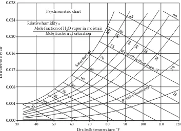
Air is required for the combustion of fossil fuels. However, atmospheric air is never dry. It contains a certain amount of moisture due to local humidity and ambient temperature conditions. This adds to the volume of air to be handled by the forced draft fan and also increases the amount of water vapor in the flue gas. The amount of moisture in air may be obtained using psychometric chart (Figure 1.1) or estimated from the equation [1]:
M = 0.622Pw/(1.033 – Pw) (1.1)
where Pw is the partial pressure of water vapor in air, kg/cm2 a. For example, at 27°C, from
steam tables, the saturated vapor pressure is 0.5069 psia = 0.0356 kg/cm2 a, and if the
rela-tive humidity is say 65%, then
Hence, M = 0.622 × 0.0231/(1.033 – 0.0231) = 0.0142 kg/kg air or 0.0142 lb/lb air. If 1000 kg of dry air is required for combustion in a boiler, the actual wet air that should be sent to the burner will be 1014.2 kg, and the boiler fan has to be sized for the volume of this amount of wet air.
Combustion Calculations
Knowing the fuel analysis, excess air, and ambient conditions, one may perform combus-tion calculacombus-tions as shown in the following text.
Example 1.1
Natural gas having CH4 = 83.4%, C2H6 = 15.8%, and N2 = 0.8 by volume is fired in a
boiler using 15% excess air. Ambient temperature is 20°C and relative humidity is 80%. Perform combustion calculations and determine the flue gas analysis.
Solution
From steam tables, the saturated vapor pressure at 20°C (68°F) is 0.34 psia = 0.0239 kg/cm2 a.
At 80% relative humidity, Pw = 0.8 × 0.0239 = 0.0191 kg/cm2 a 0.028
0.024
0.020
Relative humidity =
Mole fraction of H2O vapor in moist air Mole fraction at saturation
Psychrometric chart 0.016 0.012 0.008 0.004 0.000 40 45 50 55 60 65 70 75 Wet-b ulb tem
perature , °F 80 100 80 60 50 40 30 20 10 85 90
Dry-bulb temperature, °F
Lb water/lb dr
y air Relative humidity % Satu rate d air
30 40 50 60 70 80 90 100 110 120
32
FIGURE 1.1
M = .622 × 0.0191/(1.033 – 0.0191) = 0.012 (same information may be obtained from Figure 1.1). Combustion of methane may be expressed as CH4 +2O2 = CO2 + 2H2O or
1 mol of CH4 requires 2 mol (volumes) of O2 or 2 × 100/21 = 9.53 mol of air for
combus-tion (air contains 21% volume of oxygen and rest nitrogen). Similarly,
2C2H6+ 7O2 = 4CO2 + 6H2O or 1 mol of ethane requires 3.5 mol of O2 or 3.5 × 100/21
= 16.68 mol of dry air for combustion.
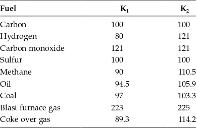
Tables 1.1 and 1.2, which give the air required for theoretical combustion of various fuel constituents, may also be used to arrive at these values.
Hence, 100 mol of fuel requires 83.4 × 9.53 + 15.8 × 16.68 = 1058.3 mol of theoretical dry air. Considering 15% excess air factor,actual dry air required = 1.15 × 1058.3 = 1217 mol. Excess air = 0.15 × 1058.3 = 158.7 mol; excess O2 = 158.7 × 0.21 = 33.3 moles and N2 formed =
0.79 × 1217 = 961 mol; air moisture = 1217 × 28.84 × 0.012/18 = 23.5 mol. (We multiplied moles by molecular weight [MW] to get the weight and then converted the moisture in air to volume basis by dividing by the MW of water vapor; here 28.84 is the MW of air and 18 that of water vapor.)
Tables 1.1 and 1.2 may also be used to get the amount of CO2, H2O, and N2 formed. For
example, 1 mol of methane forms one mole of CO2. One mole of ethane forms two moles
of CO2. Similarly, 1 mol of CH4 forms 2 mol of H2O, and 1 mol of ethane forms 3 mol of
H2O. Hence, total amount of CO2 and H2O formed is
CO2 = 83.4 × 1 + 2 × 15.8 = 115 mol;
H2O = 2 × 83.4 + 3 × 15.8 + 23.5 = 237.7 mol (23.5 mol is the air moisture);
N2 = 961+0.8 (fuel nitrogen) = 961.8 mol;
O2 (excess) = 33.3 mol
Total moles of flue gas formed = 115 + 237.7 + 961.8 + 33.3 = 1347.8 mol
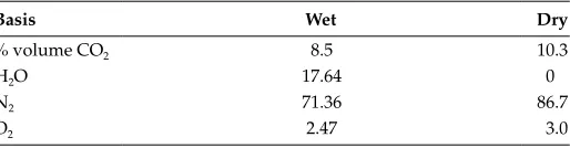
Flue Gas Analysis and Air–Flue Gas Quantities
% volume CO2 in flue gases = (115/1347.8) × 100 = 8.5%
% volume H2O = (237.7/1347.8) × 100 = 17.7%
N2 = (961.8/1347.8) × 100 = 71.36%
% O2 = (33.3/1347.8) × 100 = 2.47%.
This analysis is on wet basis. To convert to dry basis, one has to subtract the water content and recalculate the analysis. (Dry analysis is required as some instruments measure the oxygen con-tent on dry basis from which excess air is computed.)
On dry basis, CO2 = 8.5 × 100/(100 – 17.7) = 10.3%, O2 = 2.47 × 100/(100 – 17.7) = 3%, and N2 = 71.36 × 100/(100 – 17.7) = 86.7%. For efficiency calculations, one has to know the dry and wet air quantities and dry and wet flue gas formed per kg of fuel. See Table 1.3.
For nonluminous heat transfer calculations, one requires the partial pressures of CO2 and H2O. pw = 237.7/1347.8 = 0.176 atm and pc = 115/1347.8 = 0.085 atm.
MW of flue gas = 8.5 × 44 + 17.7 × 18 + 71.36 × 28 + 2.47 × 32 = 27.70.
CO2 on mass basis in flue gas is required for emission calculations as it is considered a
pollutant. % weight of CO2 in flue gas = 8.5 × 44/27.7 = 13.5. One may also compute the
emissions of CO2/million J of heat input.
Amount of fuel fired per million J of energy input on higher heating value (HHV) basis = 106/ (53.940 × 10⁶) = 0.01854 kg fuel. (HHV of the fuel is 53,940 kJ/kg [or 53.94 × 10⁶ J/kg] as shown later.) Hence, CO2 formed = 20.4 × 0.01854 × 0.135 = 0.051 kg/MM J.
S
team G
en
er
at
or
s a
n
d W
a