A Self-adaptive on-line Task Placement Algorithm for Partially Reconfigurable Systems
Yi Lu, Thomas Marconi, Georgi Gaydadjiev, Koen Bertels and Roel Meeuws
Computer Engineering Lab., TU Delft, The Netherlands
{
yilu, thomas, georgi, rmeeuws
}
@ce.et.tudelft.nl, [email protected]
Abstract
With the arrival of partial reconfiguration technology, modern FPGAs support swapping tasks in or out individually at run-time without interrupting other tasks running on the same FPGA. Al-though, implementing this feature achieves much better flexibility and device utilization, the challenge remains to quickly and effi-ciently place tasks arriving at run-time on such partially reconfig-urable systems. In this paper, we propose an algorithm to handle this on-line, run-time task placement problem. By adding logical constraints on the FPGA and introducing our resources manage-ment solution, the simulation results show our algorithm has better overall performances compared with previous reported methods in terms of task rejection number, placement quality1and execution
time.
1
Introduction
Most current FPGA-based systems treat FPGAs as slave-components. When needed, the system configures the FPGA with required logic to offload the main processor. Usually, an applica-tion running on such a system configures the whole FPGA when it starts and the configuration remains active and unchanged during the lifetime of the application. In this case, there is no requirement for a dynamic task placement algorithm. The reconfigurability makes these systems easily adaptive to different application do-mains. The reconfiguration process of the complete FPGA, how-ever, introduces long reconfiguration time and increased power consumption. In recent years, with the development of the par-tially reconfigurable FPGAs, this problem can be addressed by us-ing the partial reconfiguration support to reconfigure only the nec-essary part of the FPGA when required. Various hardware tasks can be reconfigured on such a FPGA individually without interfer-ing with other tasks already runninterfer-ing on the same FPGA. For recon-figurable systems based on such FPGAs, an application normally has a set of hardware tasks to be run on the FPGA in different stages. Such partially reconfigurable systems [13][9] increase the flexibility and resource utilization significantly, but also introduce the problem of how to manage the FPGA resources for complex multi-task situations.
There are off-line and on-line algorithms used to solve this problem. In an off-line solution, the configuration order and lo-cation of tasks are optimized when the applilo-cation is compiled. In an on-line solution, all tasks are unknown until they arrive. So,
1We built a new model to measure the placement quality, which is
de-tailed in section 4.2
when a hardware task is to be configured on the FPGA, the sys-tem searches available resources for the new task at run-time. The on-line solution provides more adaptivity to various applications and avoids the application profile step, which is time-consuming. But, because of the lack of overall information about tasks and the expectation of short allocation response times, the on-line al-gorithms have more strict requirements for resource management, free space searching time, and resource fragmentation. In this pa-per, we propose a novel algorithm for on-line task placement. The main contributions of this paper are:
• a new mechanism to dynamically manage the available FPGA resources;
• development of a self-adaptive on-line placement algorithm based on this novel FPGA resource utilization solution;
• a new model to measure placement quality and the mapping of the placement quality onto the complex plane;
• better overall performance in terms of rejection number, placement quality and algorithm execution time compared to other state of the art approaches.
In section 2 we present related approaches. Thereafter, section 3 details our on-line “IF” algorithm. Next, in section 4, we present the simulation results and evaluate performance of our and four previously proposed algorithms. Finally, we discuss future work in section 5.
2
Related Work
In 1999, Bazargan et al. [5] considered the problem of task placement on the FPGA as the well-studied 2D bin-packing prob-lem. They used some classical algorithms, e.g. first fit and best fit, for both on-line and off-line solutions. In addition, they used efficient tree data structure to manage FPGA resources. Walder et al. [15] improved Bazargan’s on-line algorithm by delaying the decision about split heuristic until a new task arrives. In addition, a hash matrix was proposed to store the available free FPGA re-sources to guarantee a constant search time. Tabero et al. [12] used vertex-lists for the same functionality, where each vertex is a possible location for an input task. A new arrival task is placed by selecting a vertex corresponding to appropriate size from the list. In [4], Ahmadinia et al. logically partitioned the FPGA in some full height slots of varying width. Tasks with close ending times are assigned in the same slot. Steiger et al. [11] described an enhanced version of Bazargan’s placement algorithm consider-ing both schedulconsider-ing and placement for an on-line solution. In [3], Ahmadinia et al. proposed a new way to manage the FPGA free resources by storing the information about used space. Also, the authors considered connectivity between tasks when placing ar-rival tasks. In [8], Koester et al. introduced an algorithm consid-ering restrictions of fixed location resources (e.g. BRAM). They introduced the occupancy possibility weight of different area and used it to place an input task in the area with least possibility of being occupied by further tasks. The authors implemented this algorithm on Virtex II FPGA. In [6][10][7], inter-task communi-cation channels using fixed hardware logic were proposed for the 1D FPGA resource partitioning. In [14], Walder et al. investigated placement and transformation of non-rectangular tasks.
Given the above analysis and description, we aim to develop an on-line task placement algorithm performing not only efficient resource usage but also fast task allocation time.
During our study of the on-line placement, we also noticed that in these previously proposed task online placement algorithms, the resource wastage and (or) task rejection number are calculated in-dividually to measure the placement quality. However, these con-siderations can not reflect the overall situation of placement qual-ity (also referred to as the efficiency of using FPGA) during the application execution because of the lack of the rejected task de-tails. In this paper, we build a novel model for placement quality measurement when these two FPGA partitioning models are used. The model consists of resource wastage from both placed task side and rejected task side as well as the information of task rejection rate and task life time. This model will be detailed in section 4.2.
3
Immediate Fit
The algorithm proposed in this paper is named ”Immediate Fit”(IF). The current version of our IF algorithm supports non-preemptive tasks. The IF algorithm is characterized by fast alloca-tion of available FPGA area and highly efficient use of the FPGA resources. In this section we first discuss the motivation and goal of proposing our IF algorithm. Thereafter, we present definitions needed in the following discussion. Next, the current constraints adding on the IF are described. Finally, the ”IF” algorithm opera-tion processing and resource management are detailed.
3.1
Motivation and goal
As mentioned in section 2, the algorithms based on the fixed pre-partitioned FPGA models usually have faster free space allocation
time compared to the algorithms based on the flexibly partitioned FPGA models, because only limit pre-partitioned FPGA areas are searched to find a fit location. However, the latter algorithms have higher FPGA resource usage than the former algorithms because an arrival task is just located to the area it needs. The IF algo-rithm proposed in this paper aims at keeping the advantages of the algorithms using the two FPGA models, as well as eliminating their disadvantages. In order to fulfill this goal, the IF algorithm 1) initially partitions the FPGA surface into blocks to bring the fast allocation feature of the pre-partitioned FPGA model; 2) imple-ments a set of resource redistribution operations on these initially partitioned blocks to make highly efficient use of the FPGA re-sources (the operations also implement defragmentation function to avoid quickly increased fragmentation in relation to the number of placed tasks).
3.2
Definitions
Initial partitioning of the FPGA:
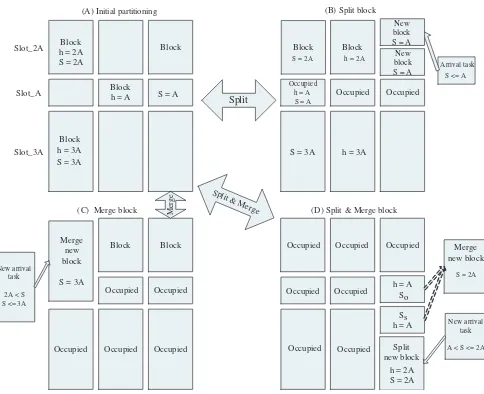
Initially, the FPGA is logically partitioned into three different size blocks: the small size, the medium size and the large size. For the remainder of this paper, in order to make the explanation of our IF algorithm simple, we will assume that in the initial FPGA parti-tioning three blocks for each size are available and they are located in the same slot, as shown in Figure 1 (A). The small blocks are located in the middle and all blocks have the same width in order to make more efficient resource usage as described in the ”Block repartition mechanism” part. Given the minimum partial reconfig-uration frame of the Virtex 4 FPGA2and constraints of current de-sign flows for partially reconfigurable systems, these logical con-straints on the FPGA are reasonable and practical. The number and size of blocks can be adjusted in advance according to an ap-plication’s specification.
Block repartition mechanism:
In order to use the FPGA resources more efficiently, the IF algo-rithm employs a split, merge and recover mechanism. Block split and merge happens when blocks with required size are all occu-pied. New blocks with the required size can be created via the split and merge process if enough free space is available in other different size blocks. When these new blocks are freed later, the recovery process provides area defragmentation function by re-assembling these freed blocks back to the original blocks. The IF algorithm always tries to maintain the initial partitioning which guarantees all blocks can be repartitioned later via split and merge process when required. There are three types of split and merge processes: split only, merge only, and split-merge. They corre-spond to (B), (C), and (D) in Figure 1 respectively. A split only process splits a large size block into smaller size blocks. The re-verse is merge. For example, in Figure 1(B), all A-size blocks (blocks with size equal to A) are occupied, when a new A-size task arrives. A 2A-size block is split into two A-size blocks which can be used by the new arrival task. conversely, in Figure 1(C), A new 3A-size block is generated via merge process. The merge-split process will be described in section 3.4.
Linked lists used for resource management:
Fast space allocation requires an efficient way to represent the al-locatable space. Therefore, in our algorithm, we use linked lists to represent the resource availability on the FPGA. We defined two different linked list: free space linked list (FSLL) and used space
2For the Virtex 4 FPGAs[2], the minimum reconfiguration frame is a
Occupied
(D) Split & Merge block
New arrival
Figure 1. Operations on the blocks
linked list (USLL). The FSLL stores available free blocks and the USLL stores the occupied blocks. In the IF algorithm, blocks with same size are represented by a specific FSLL and a specific USLL together, e.g. in the initial FPGA partitioning used in this paper shown in Figure 1 (A), the small blocks inslot A(h=A)can be
With this linked list data structure, updating the information about the FPGA resource utilization becomes much simpler. An update only requires the insertion or removal of the related nodes when blocks are assigned or freed, information stored in other nodes in the linked list does not have to be modified.
3.3
Current constraints of the IF
algo-rithm
The current implementation of the IF algorithm has the follow-ing constraints that apply: (i) the IF algorithm only supports split and merge in the vertical dimension, as described in section 3.2 and 3.4; (ii) the current IF algorithm considers the FPGA as a ho-mogeneous architecture; (iii) all input tasks used in our simulation are assumed to have a rectangular shape and must fit the shape of the pre-partitioned blocks (see section 4); (iv) each input task can only be placed in the block with corresponding size. This means an input task with small size can not be directly placed in a medium or large size block. The only way to use these resources is via the block repartition mechanism described in section 3.2; (v) consid-ering the lower number of biggest blocks (even with the potential biggest blocks via merge process) compared to the number of other size blocks, we set a higher priority to the largest size block. In the current IF algorithm, this means the tasks in the smallest size range can not use the resources initially assigned to the largest blocks.
3.4
Algorithm process and resources
man-agement
When a task arrives, the FSLL representing the best fit blocks is chosen based on the size (S) of the arrival task. Thereafter, if there are nodes existing in the FSLL at that moment, the available free block represented by the first node is assigned to the new arrival task, otherwise the split and merge process is initiated as shown in the IF algorithm in the Figure 2. To reflect the current resource
1. /* for each arrival task */
3. /* output: position of suitable locaiton
5. {
2. /* input parameters: task_size, task_exe_time */
4. search_location(task_size, task_exe_time)
12. else if((block_c = do_merge_split(task_size)) != NULL) IF Algorithm :
18. } 19. end IF;
9. update_related_linked_lists(block_c, task_exe_time);
14. update_related_linked_lists(block_c, task_exe_time);
20. update_related_linked_lists(block, time) 21. {
24. } 25. end update;
23. assing the "block" with "time" and add "block" into the USLL 6. block_list_x * = search_which_block_list(task_size);
7. if((block_c = block_list_x −> next_block) != NULL) //Normal search
22. remove the "block" from the FSLL respresenting block_list_x;
Figure 2. IF algorithm
usage, the FSLL and USLL are updated when a block is occupied or freed, e.g. when the first block ofslot Ais occupied, as shown in Figure 1 (B), the initial FSLL and USLL will be updated as follows:
{slot A F SLL} → {slot A block2} → {slot A block3} → {N U LL}
{slot A U SLL} → {slot A block1} → {N U LL}
3A-size
Before split and merge After split and merge
Figure 3. Linked list update
their twin brother and original block (3A-size block for this case). These pointers are used to recover the original block from the twin blocks. This recovery process is initiated during the resource up-date process if the twin blocks are all freed.
After the split process, the new arrival 2A-size task is allocated into the 2A-size twin block. The A-size twin block can be added into the FSLL representing the A-size block, the corresponding linked lists update is shown in Figure 3. The A-size twin block can also be merged with another A-size block to a new 2A-size block, if the initially partitioned A-size block above is available, e.g. the A-size twin block (Ss) and the above A-size block (So)
are merged into a new 2A-size block as shown in the right side of Figure 1 (D).
When an occupied block is freed, its corresponding node will be removed from the USLL and added back to the FSLL. If the block is a pre-partitioned block, it will be added back to the first position in the corresponding FSLL; if the block is created by split and merge processing, this block will be added to the end of the corresponding FSLL. The current IF algorithm does not support the reallocation of placed tasks, so by adding the freed created block to the end of the FSLL, the created block has the lowest possibility to be used by the coming tasks. When the update pro-cess initializes, the created block will be recovered back to the pre-partitioned block if it is free.
Using the split and merge process, the resources on the FPGA can be dynamically redistributed according to arrival tasks. And during the update stage, if freed redistributed blocks are found, the recovery process will be initialized to re-assemble these blocks into the original pre-partitioned blocks which can be reused by all different size tasks arriving in the future. In section 4.4 we will present related simulation results about how many time the “split and merge” and recovery process are initialized during application execution.
4
Experimental evaluation
We compared the IF algorithm with fixed 1D, fixed 2D, Bazargan’s first fit (BFF) and best fit (BBF) in terms of rejection number, placement quality and execution time. All algorithms are programmed using C, and executed under Linux 2.6 with Intel(R) Pentium(R) 4 CPU 3.00GHz.
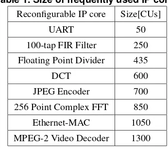
Each input task used in the simulation has two parameters (S, T). S is the size of an input task and T is the computation time for a task running on the FPGA. For BFF and BBF, the height (H) and width (W) of tasks are also provided, which are used in the SSEG (Shorter Segment) segmentation heuristic [5]. According to the results shown in [5], the SSEG heuristic has the best performance on a similar size FPGA as used in this paper, compared to other
Table 1. Size of frequently used IP cores
Reconfigurable IP core Size[CUs]
UART 50
100-tap FIR Filter 250 Floating Point Divider 435
DCT 600
JPEG Encoder 700
256 Point Complex FFT 850
Ethernet-MAC 1050
MPEG-2 Video Decoder 1300
heuristics. Simulations of all algorithms related to this paper are implemented on the same size FPGA with an array of 96 ×96 configurable units (CUs).
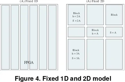
vari-ous applications, the number and size of blocks can be adjusted in advance to optimize performance. For the 2D algorithm, the fixed partitioning is the same as the initial partitioning of IF algorithm; for the 1D algorithm, six full height slots are set with a width of 16, as shown in figure 4. Each slot is suitable for the largest task
Block
(A) Fixed 2D
Block h = 2A
Block h = A
Block h = 3A S = 2A
S = 3A
S = A
(A) Fixed 1D
FPGA
Figure 4. Fixed 1D and 2D model
size used in the simulation. All tasks used for the 1D algorithm simulation are constrained within the partitioned slot, which is the rectangle of 96×16 CUs.
4.1
Rejection number
For each task type, 100 sets were tested in our simulation. Each set has 1000 tasks. The rejection number is defined as the number of rejected tasks in one set. In our current algorithm, only non-preemptive tasks are supported. If a task is accepted, it will operate on the FPGA for the period of its computation time T. If there is no suitable location for the arrival task, this task will be rejected and it can only run on the main processor as a software module. The average value of the rejection numbers for each set is given. In Figure 5, the rejection number for 1D is the same irrespective
Rejection Number
0 50 100 150 200 250 300 350 400 450
T500 T1000 T1500 T[500, 1500]
1D
2D
BFF
BBF
IF
Figure 5. Rejection number per set
the task sizes, which is around 70. A similar situation holds for 2D for the first three task types, however the rejection number is much higher, i.e. around 400. This is because the number of pre-partitioned blocks used in 1D and 2D is fixed. For each task type of T500, T1000 and T1500, 1D can provide 6 blocks, while 2D can only give 3 blocks. The IF shows a lower rejection number, which is on the average 23. The BFF and BBF outperform all other algorithm in simulating with T500. However, The performance of
BFF and BBF decreases when the task size increases. The reason is that the area becomes more and more fragmented which will result in a higher rejection number. This phenomenon is more obvious for large size input tasks as shown in T1000 and T1500. The rejection number of IF is around 3.7 times and 2.3 times lower than that of BFF and BBF in T1000 and T1500 respectively. The IF algorithm, with split and merge process, can provide as many required size blocks as possible. For the mixed size tasks, the IF also achieves the best performance, the rejection numbers are 3, 3.5, 2.7 and 1.7 times lower compared with 1D, 2D, BFF and BBF respectively. Overall, the IF algorithm has lower rejection numbers compared to other algorithms except for BFF and BBF in smallest task sizes.
4.2
Placement quality
In this subsection, we will describe the proposed new model for measuring placement quality. Firstly, some definitions used in the following discussion are given; then the mathematical expres-sions of the model are explained; finally, the simulation results of the model is presented and analyzed.
Waste rectangle: in the flexibly partitioned FPGA area model, the waste rectangle is defined as the rectangular area smaller than the minimum task size in the currently running application, e.g. in figure 6 (a) the areaAis smaller than the size of any task in the application, so this areaAis a waste rectangle which can not fit any task in the application.
Real resource wastage: in the pre-partitioned FPGA area model, the real resource wastage is defined as the area unoccupied by the placed task in its assigned pre-partitioned block as shown in figure 6 (b), which is referred to asmismatch area; in the flexibly parti-tioned FPGA area model, the real resource wastage is the sum of the area of the waste rectangles. In previous task placement algo-rithms, only this real resource wastage is taken into account when calculating resource wastage.
Imaginary resource wastage: for both FPGA area models, the imaginary resource wastage is defined as the area designed for the rejected task when running on the FPGA. This definition is based on the assumption that the task is successfully allocated on the FPGA.
Life time: for a hardware task or an area on the FPGA, the life time means the period they exist on the FPGA; for an application, the life time means the period from the beginning of the applica-tion to the ending of the applicaapplica-tion.
A Placed task 1
Placed task 2
Placed task Mismatch
area
Pre -partitioned boock
(a) (b)
Figure 6. Resource wastage by placed tasks
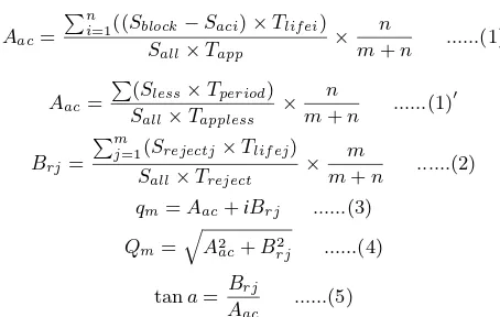
contains the following equations:
Aac=
Pn
i=1((Sblock−Saci)×Tlif ei)
Sall×Tapp
× n
m+n ...(1)
Aac=
P
(Sless×Tperiod)
Sall×Tappless
× n
m+n ...(1)
′
Brj=
Pm
j=1(Srejectj×Tlif ej)
Sall×Treject
× m
m+n ...(2) qm=Aac+iBrj ...(3)
Qm=
q A2
ac+B
2
rj ...(4)
tana=Brj Aac
...(5)
In equation (1),Sblockrepresents the size of the block assigned to
the accepted taski;Saciis the size of accepted taski;Tlif eiis the
life time of taski;Tappis the application life time. In equation
(1)′,S
lessis the size of a waste rectangle;Tperiodis the life time
for the waste rectangle;Tapplessis the total application execution
time when there are waste rectangles on the FPGA. In equation (2),
Srejectjstands for the size of the rejected taskjandTrejectfor is
the total life time of rejected tasks if they are mapped on the FPGA. For these three equations,Sallis the size of the complete FPGA;
mandnstand for total number of accepted tasks and rejected tasks respectively.
As shown in equation (3), the placement quality defined in this paper uses complex number whose real partAac and imaginary
partBrjare related to real resource waste and imaginary resource
waste respectively. In equation (1) where theAacis defined for
pre-partitioned FPGA area model (e.g. fixed 1D, fixed 2D and IF in this paper), the numerator represents the sum of the product of real resource wastage and its life time; the denominator is given as the product of the complete FPGA area and the life time of the application; the quotient of them reflects that how many percents of the FPGA resource are wasted by placed tasks during the ap-plication execution. Then by multiplying the rate of the placed task taking from the number of total input tasks, we average the resource wastage caused by placed tasks. In equation (1)′, theA
ac
is defined for flexibly partitioned FPGA area model (e.g. BBF and BFF). The equation (2) definesBrj for both pre-partitioned and
flexibly partitioned FGPA models. The equation (1)′and (2) holds
similar explanation as that of equation (1).
Equation (4) gives the absolute value of placement quality (Abs placement quality) which is used for our comparison as shown in Figure 7. For online placement algorithms, smallAbsplacement quality are expected. The small value reflects the low real and imaginary resource wastage, which implies that the FPGA is effi-ciently used during the application execution. In equation (5), the anglea[degree◦] is namedcontribution factor, the value ofa
re-flects the contribution to theAbsplacement quality from both real resource wastage side and imaginary resource wastage side. Large values for aimply relatively larger average imaginary resource wastage (Brj) compared to real resource wastage(Aac) during the
application execution. This corresponds to three situations: 1) rel-atively large number of tasks are rejected, 2) few tasks with long life time are rejected, 3) combination of 1) and 2). These cases imply that the task placement algorithm used in the reconfigurable system can not efficiently use the FPGA when running the appli-cation.
In the 1D model, the fixed slots are partitioned to fit the largest task. A small task placed in such a slot brings a large amount of
Abs value of placement quality
0.0% 2.0% 4.0% 6.0% 8.0% 10.0% 12.0% 14.0%
T500 T1000 T1500 T[500, 1500]
1D 2D
BFF
BBF
IF
Figure 7. Placement quality
real resource wastage which gives a large Absplacement qual-ity. That is why theAbsplacement quality of the 1D decreases when the input task size increases as shown in Figure 7. For the 2D model, theAbsplacement quality increases when the task size gets larger. The reason is that the number of blocks corresponding to each task type is fixed, so theAbsplacement quality seems to be proportional to the task size. BFF and BBF perform better with the small task size (T500) and the mixed task size(T[500, 1500]). However, with task size increasing, theAbsplacement quality in-creases dramatically as shown in T1000 and T1500 of Figure 7. This is because the larger task set implies the larger waste rect-angles. These waste rectangles can not fit any task in the appli-cation during their life time, which further bring high task rejec-tion numbers. Thanks to the block repartirejec-tion mechanism and the pre-partitioning on the FPGA, the IF algorithm provides required blocks as many as possible and places the new tasks in the blocks best fit. Overall, the IF has lower averageAbsplacement quality (2.5%) compared to 1D (7.8%) and 2D (3.8%), and it achieves bet-ter performance (2.7%) compared to BFF and BBF in T1000 and T1500 (4.2%).
As shown in Figure 7, the algorithms have similarAbs place-ment quality in T1000 except for 1D. In this situation, the val-ues ofAbsplacement quality can not explicitly show the perfor-mance differences of these algorithms. By using ourP QM-IC model, the coupled placement quality vectors can be mapped onto the complex number plane as shown in the left side of Figure 8 (The right side shows the related data), which explicitly depict the algorithm performances during the application execution. In order to make the figure clear, we did not follow exact scales, but kept the originally related positions of these placement quality vectors. For the 1D, the small contribution factora(3.67◦) and largeAbs
1D
Figure 8. Placement quality in complex plane
4.3
Algorithm execution time
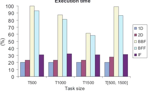
An important aspect of dynamic partial reconfiguration is the speed with which an allocation can be computed. In the algorithm execution time evaluation, we compare the IF algorithm execution time with execution time of 1D, 2D, BBF and BFF. The longest computation time, which is for BBF using T500, is used as the baseline. Execution time for other items will be given as a per-centage to this baseline. In our implementation of 1D and 2D, we also use linked lists to represent resources usage.
Execution time
T500 T1000 T1500 T[500, 1500]
Task size
Figure 9. Algorithm execution time
It can be observed from Figure 9 that the 1D and 2D algo-rithms have the shortest execution time; the execution time of the IF is also short, but 10% longer compared with 1D and 2D. This is because the 1D and 2D algorithms only check the first node in the free space linked list for an arriving task, while the IF algorithm further can implement the split and merge process for task alloca-tion if required. The computaalloca-tional complexity for each of them is O(1).
The BFF and BBF have the longest execution time. In BBF, all available free rectangles will be examined to find the best fit one for each arriving task, while the BFF only chooses the first fit free rectangle in each task type. The computational complexity for BBF isO(n)and the worst case complexity of BFF (the free rectangles are additionally linked into a linear list [11] andnis the number of tasks placed on the FPGA), is alsoO(n). For larger
Table 2. Data about stages during execution
No. of No. of No. of Split and Recovery
B16 B32 B48 merge calls calls
Initial 3 3 3 -
-SimTmix1 5 2 3 242 249
SimTmix2 1.39 6.22 1.39 148 177
SimTmix3 1 1 5 222 231
task sizes, execution time for both of them decreases. This is be-cause for larger size tasks, there are relatively fewer tasks that can be allocated. Hence the number of free rectangles in the data struc-ture is less than that for smaller size tasks, the time used in both algorithms for finding a free rectangle and data structure update is reduced.
Overall, although the execution time of IF is around 1.5x longer than that of 1D and 2D, the superior performance in terms of the rejection number and resource wastage compensate for slightly longer computation time. Compared to BBF and BFF, our IF al-gorithm has 2x to 3.3x speedup.
4.4
Self adaptive resource management
As shown in previous parts of this evaluation section, the algo-rithms based on the fixed pre-partitioned FPGA models (e.g. the 1D and 2D used in this paper) bring worse overall performance in terms of rejection number and placement quality compared to those of the algorithms using the flexibly partitioned FPGA model (e.g. the BFF and BBF in this paper). The reason is attributed to the mismatch between arriving tasks and pre-partitioned blocks. There are two kinds of mismatch, accept mismatch and reject mis-match. In an accept mismatch, a small size task is placed in a large size block, which bring obvious real resource wastage. In a reject mismatch, a new large size task can not be assigned to the FPGA resources which are pre-partitioned as small size blocks, even if the total available resource is suitable for the new task. This brings a high task rejection number and a high imaginary re-source wastage. However, the fixed pre-partitioned model makes resource management much easier compared to the flexibly parti-tioned FPGA model. So the time used for free space searching and resource data structure updating are much shorter.
The block repartition mechanism used in the IF algorithm ful-fills the resources self adaptation function. During an application, the split and merge process provides as many required size blocks as possible, while the recovery process reassembles these blocks to the original blocks when they are released, which makes the re-sources highly reusable. In this way, there is lower possibility of the two kinds of mismatch happening in the IF algorithm.
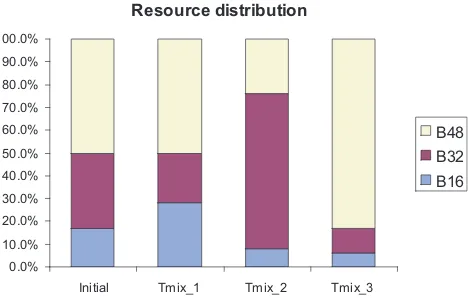
A mixed task set,Tmix(we consider it as an application), is
generated to simulate this resource self adaptation mechanism. In order to demonstrate this capability, we run the following simu-lation. There are three continuously sequential stages in the ap-plication: Tmix 1(724, 171, 105), Tmix 2(164, 715, 119), and
Tmix 3(200, 256, 542). Different stages have their own demand
for block size. For example, theTmix 2stage contains 164T500
Resource distribution
0.0% 10.0% 20.0% 30.0% 40.0% 50.0% 60.0% 70.0% 80.0% 90.0% 100.0%
Initial Tmix_1 Tmix_2 Tmix_3
B48 B32 B16
Figure 10. Resources automatic redistribu-tion
of the application. TheB16,B32andB64refer to the small block,
medium block and large block respectively. As shown in figure 10 and table 2, during different stages, the IF algorithm automatically redistributes the FPGA resources at run-time according to various demands. This means that the area allocation and subsequent us-age reflects the specific application requirements for the FPGA re-sources. For example, during theTmix 2stage, the average
num-ber of medium size blocks is 6.22 on the FPGA. Corresponding to Figure 10, around 70% of the FPGA resources are used for the 6.22 medium size blocks during that stage. The same situation can be observed in other stages. In the last two columns of the table 2, the initialization times of “split and merge” and recovery func-tions during different stages are shown, these two types of opera-tions brings the flexible and expected resource redistribution and resource recovery during the application execution. Without these operations, the IF will perform similarly to the fixed 2D, which are much worse than the experimental results of the IF algorithm as shown earlier.
5
Conclusion and future work
In this paper, we proposed a new algorithm for on-line task placement for the FPGA-based partial reconfiguration system. In spite of certain constraints that apply, our experimental validation has shown that the IF algorithm has better overall performance for all task sizes. In the future, our work will focus on: (i) relaxing some of the constraints to make the IF algorithm more flexible; (ii) to support more specific location requirement, such as the arrival task requirement for I/O pins; (iii) to provide preemptive tasks support, we are planning to develop an on-line scheduler, which is another key part for preemptive support; (iv) task relocation; (v) to provide flexible inter-task connection.
Acknowledgment: This work is sponsored by the hArtes project (IST-035143) supported by the Sixth Framework Pro-gramme of the European Community under the thematic area “Embedded Systems”.
References
[1] Intellectual Property. http://www.xilinx.com/ipcenter/.
[2] Virtex 4 user guide.
http://direct.xilinx.com/bvdocs/userguides/ug070.pdf. [3] A. Ahmadinia, C. Bobda, S. P. Fekete, J. Teich, and J. C.
van der Veen. Optimal free-space management and routing-conscious dynamic placement for reconfigurable devices. In IEEE Transactions on Computers, volume 56, pages 673– 680, May 2007.
[4] A. Ahmadinia, C. Bobda, and J. Teich. A dynamic schedul-ing and placement algorithm for reconfigurable hardware. In In Proceedings of 17th International Conference on Archi-tecture of Computing Systems (ARCS 2004), volume 2981, pages 125–139. Springer-Verlag,, 2004.
[5] K. Bazargan, R. Kastner, and M. Sarrafzadeh. Fast tem-plate placement for reconfigurable computing systems. In In IEEE Design and Test of Computers, volume 17, pages 68–83, 2000.
[6] G. Brebner and O. Diessel. Chip-based reconfigurable task management. Inthe 11th International Conference on Field Programmable Logic and Application, FPL 2001, pages 182–191, Belfast, Northern Ireland, Aug 2001.
[7] M. P. H. Kalte and U. Ruckert. System-on-programmable-chip approach enabling online fine-grained 1d-placement. In n 11th Reconfigurable Architectures Workshop (RAW 2004), 2004.
[8] M. Koester, M. Porrmann, and H. Kalte. Task placement for heterogeneous reconfigurable architecture. InIn Pro-ceedings of the IEEE International Conference on Field-Programmable Technology (FPT), Singapore, December 11-14, 2005.
[9] Y. Lu and N. Bergmann. Dynamic loading of peripher-als on reconfigurable system-on-chip. InIn Proceedings of the IEEE International Conference on Field-Programmable Technology (FPT), Singapore, December 11-14, 2005. [10] C. Steiger, H. Walder, and M. Platzner. Heuristics for
on-line scheduling real-time tasks to partially reconfigurable devices. Inthe 13th International Conference on Field Pro-grammable Logic and Application, FPL 2003, Lisbon, Por-tugal, Sept., 2003.
[11] C. Steiger, H. Walder, M. Platzner, and L. Thiele. Online scheduling and placement of real-time tasks to partially re-configurable devices. InIn Proceedings 24th IEEE Inter-national Real-Time Systems Symposium (RTSS), pages 224– 235, Cancun, Mexico, December 2003.
[12] J. Tabero, J. Septien, H. Mecha, and D. Mozos. Low frag-mentation heuristic for task placement in 2d rtr hw man-agement. In14th International Conference on Field Pro-grammable Logic and Application, FPL 2004, pages 241– 250, Antwerp, Belgium, Sept. 2004.
[13] S. Vassiliadis, S. Wong, G. Gaydadjiev, K. Bertels, G. Kuz-manov, and E. M. Panainte. The molen polymorphic pro-cessor. InIEEE Transactions on Computers archive, vol-ume 53, Nov. 2004.