•
•
•
•
•
•
•
Warren Gay
Mastering
the
Raspberry Pi
A COMPLETE REFERENCE GUIDE
AND PROJECT IDEA GENERATOR
▸ Baca selengkapnya: download 123dok free
(2)For your convenience Apress has placed some of the front
matter material after the index. Please use the Bookmarks
v
Contents at a Glance
About the Author ...
xxvii
About the Technical Reviewer ...
xxix
Acknowledgments ...
xxxi
Chapter 1: Why This Book?
■
...
1
Chapter 2: The Raspberry Pi
■
...
5
Chapter 3: Preparation
■
...
9
Chapter 4: Power
■
...
17
Chapter 5: Header Strips, LEDs, and Reset
■
...
29
Chapter 6: SDRAM
■
...
37
Chapter 7: CPU
■
...
53
Chapter 8: USB
■
...
69
Chapter 9: Ethernet
■
...
75
Chapter 10: SD Card Storage
■
...
83
Chapter 11: UART
■
...
91
Chapter 12: GPIO
■
...
117
Chapter 13: 1-Wire Driver
■
...
157
Chapter 14: I2C Bus
■
...
167
Chapter 15: SPI Bus
■
...
177
Chapter 16: Boot
■
...
191
Chapter 17: Initialization
Chapter 18: vcgencmd
Appendix F: Mac OS X Tips
■
...
455
Bibliography
■
...
457
1
Why This Book?
This book developed out of a need for an in-depth work about the Raspberry Pi that just didn’t seem to exist. If I had found one, I would have gladly purchased it. A quick survey revealed a large number of “how to get started” books. But I pined for something with the kind of meat that appeals to engineering types. Give me numbers, formulas, and design procedures.
Almost all of that information is available out there on the Internet somewhere. But I discovered that some questions take considerable time to research. If you know exactly where to look, the answer is right there. But if you’re just starting out with the Raspberry Pi, you have several online Easter-egg hunts ahead of you. How much is your time worth?
Here’s a short sample of some of the questions answered in this book:
How much current can a general purpose input/output (GPIO) port source or sink? •
What is the resistance of the GPIO internal pull-up/pull-down resistor? •
Which GPIO does the 1-Wire interface use? •
What is the GPIO voltage range for a 0 bit or 1 bit? •
How do you budget the GPIO power? •
Some of these questions have simple answers, while others require an “it depends” explanation. You might be wondering why you need to know the internal GPIO pull-up resistance. Chapter 27 discusses this in connection with motor driver interfaces and what happens at boot time. A number of questions arise when you start designing interfaces to the outside world. While you may not aspire to be an electronics engineer, it helps to think like one.
Who Needs This Book?
This is an important question and the answer, of course, depends on what you are looking for. So let’s cut to the chase. This book is
Not an easy “how to get started” book (These are plentiful.) •
Not a book about Scratch, Python, or Ruby programming •
Not a “download package X, configure it, and install it thusly” book •
Not a media server or retro games console handbook •
This book is targeted to those who have the following:
A college/university level or hobbyist interest •
Some exposure to Linux (Raspbian Linux) •
Some exposure to the C programming language •
Some exposure to digital electronics •
This Book Is Primarily About
In very broad terms, this book can be described primarily as follows:
A Raspberry Pi hardware reference, with software exploration •
An electronics interfacing projects book, exploring the hardware and software to drive it •
In a nutshell, it is a reference and projects book for the Raspberry Pi. The reference coverage is extensive compared to other offerings. A considerable section of the book is also dedicated to projects. I believe that this combination makes it one of the best choices for a book investment.
An ever-increasing number of interface boards can be purchased for the Pi, and the choices increase with each passing month. However, this book takes a “bare metal” approach and does not use any additional extender/adapter board solutions. You can, of course, use them, but they are not required.
This text also uses a “poor student” approach, using cheap solutions that can be purchased as Buy It Now sales on eBay. These then are directly interfaced to the GPIO pins, and I discuss the challenges and safety precautions as required. This approach should also meet the needs of the hobbyist on a limited budget.
You should have a beginning understanding of the C programming language to get the most out of the software presented. Since the projects involve electronic interfacing, a beginning understanding of digital electronics is also assumed. The book isn’t designed to teach electronics, but some formulas and design procedures are presented.
Even those with no interest in programming or electronics will find the wealth of reference material in this book worth owning. The back of the book contains a bibliography for those who want to research topics further.
Learning Approach
Many times a construction article in a magazine or a book will focus on providing the reader with a virtual kit. By this, I mean that every tool, nut and bolt, component, and raw material is laid out, which if properly assembled, will achieve the project’s end purpose. This is fine for those who have no subject area knowledge but want to achieve that end result.
However, this book does not use that approach. The goal of this book is to help you learn how to design solutions for your Rasbperry Pi. You cannot learn design if you’re not allowed to think for yourself! For this reason, I encourage the substitution of parts and design changes. Considerable effort is expended in design procedure. This book avoids a “here is exactly how you do it” approach that many online projects use.
I explain the challenges that must be reviewed, and how they are evaluated and overcome. One simple example is the 2N2222A transistor driver (see Chapter 12), where the design procedure is provided. If you choose to use a different junk box transistor, you can calculate the base resistor needed, knowing its HFE (or measured on a digital multimeter). I provide a recipe of sorts, but you are not required to use the exact same ingredients.
3
It is intended that you, the reader, not use the presented projects as exact recipes to be followed. Use them asguidelines. Explore them as presented first if you like, but do not be afraid to substitute or alter them in some way. By the time you read this book, some PCBs used here may no longer be available. Clever eBay searches for chip numbers may turn up other manufactured PCB solutions. The text identifies the kind of things to watch out for, like unwanted pull-up resistors and how to locate them.
By all means, change the presented software! It costs nothing to customize software. Experiment with it. The programs are purposely provided in a “raw” form. They are not meant to be deployed as finished solutions. They are boiled down as much as possible to be easily read and understood. In some cases, error checking was removed to make the code more readable. All software provided in this book is placed in the public domain with no restrictions. Mold it to your needs.
If you follow the projects presented—or better, try them all—you’ll be in a good position to develop new interface projects of your own design. You’ll know what questions to ask and how to research solutions. You’ll know how to interface 3-volt logic to 5-volt logic systems. You’ll know how to plan for the state of the GPIO outputs as the Raspberry Pi boots up, when driving external circuits. Experience is the best teacher.
Organization of This Book
This book is organized into four major parts. The first part is an introduction, which does not present “how to get started” material but does cover topics like static IP addressing, SSH, and VNC access. I’ll otherwise assume that you already have all the “getting started” material that you need.
Part 2 is a large reference section dedicated to the Raspberry Pi hardware. It begins with power supply topics, header strips (GPIO pins), LEDs, and how to wire a reset button. Additional chapters cover SDRAM, CPU, USB, Ethernet (wired and wireless), SD cards, and UART (including RS-232 adapters). A large focus chapter on GPIO is presented. Additional chapters cover Linux driver access to 1-Wire devices, the I2C bus, and the SPI bus. Each chapter examines the hardware and then the software API for it.
In Part 3, important software aspects of the Raspberry Pi are examined. This part starts with a full exploration of the boot process, initialization (from boot to command prompt), and vcgencmd and its options. The Linux console and the serial console are documented. Finally, software development chapters on cross- compiling the kernel are covered in detail.
Part 4 is the fun part of the book, where you apply what you learned to various projects. All of the projects are inexpensive and easy to build. They include interfacing 1-Wire sensors, an I2C GPIO extender, a nunchuk as a mouse, an infrared reader, unipolar and bipolar stepper motor drivers, switch debouncing, PWM, and a remote sensor/console. There is also a real-time clock project for the Model A owner (which can be tried on the Model B). These cover the majority of the interfacing use cases that you will encounter.
The meanings of acronyms used in this advanced level book will be taken for granted. As the reader, you are likely familiar with the terms used. If however, you find yourself in need of clarification, Appendix A contains an extensive glossary of terms.
Software in This Book
I generally dislike the “download this guy’s package X from here and install it thusly” approach. The problem is that the magic remains buried inside package X, which may not always deliver in the ways that you need. Unless you study their source code, you become what ham radio people call an appliance operator. You learn how to install and configure things but you don’t learn how they work.
For this reason, a bare metal approach is used. The code presented is unobstructed by hidden software layers. It is also independent of the changes that might occur to magic package X over time. Consequently, it is hoped that the programs that compile today will continue to compile successfully in the years to come.
The software listings have been kept as short as possible. Books filled with pages of code listings tend to be “fluffy.” To keep the listing content reduced, the unusual technique of #include-ing shared code is often used. Normally, program units are compiled separately and linked together at the end. But that approach requires header files, which would just fill more pages with listings.
The source code used in this book is available for download from this website:
git://github.com/ve3wwg/raspberry_pi.git
There you can also obtain the associated make files. The git clone command can be used on your Raspberry Pi as follows:
$ git clone git://github.com/ve3wwg/raspberry_pi.git
To build a given project, simply change to the project subdirectory and type the following:
$ cd ./raspberry_pi $ make
If you are making program changes and want to force a rebuild from scratch, simply use this:
$ make clobber all
Final Words
If you are still reading, you are considering purchasing or have purchased this book. That makes me truly excited for you, because chapters of great Raspberry Pi fun are in your hands! Think of this book as a Raspberry Pi owners manual with fun reference projects included. Some may view it as a cookbook, containing basic idea recipes that can be tailored to personal needs. If you own a Raspberry Pi, you need this book!
A lot of effort went into including photos, figures, and tables. These make the book instantly more useful as a reference and enjoyable to read. Additional effort went into making the cross-references to other areas of the book instantly available.
5
The Raspberry Pi
Before considering the details about each resource within the Raspberry Pi, it is useful to take a high-level inventory. In this chapter, let’s just list what you get when you purchase a Pi.
In later chapters, you’ll be looking at each resource from two perspectives:
The hardware itself—what it is and how it works •
The driving software and API behind it •
In some cases, the hardware will have one or more kernel modules behind it, forming the device driver layer. They expose a software API that interfaces between the application and the hardware device. For example, applications communicate with the driver by using ioctl(2) calls, while the driver communicates with the I2C devices on the bus. The /sys/class file system is another way that device drivers expose themselves to applications. You’ll see this when you examine GPIO in Chapter 12.
There are some cases where drivers don’t currently exist in Raspbian Linux. An example is the Pi’s PWM peripheral that you’ll look at in Chapter 30. Here we must map the device’s registers into the application memory space and drive the peripheral directly from the application. Both direct access and driver access have their advantages and disadvantages.
So while our summary inventory here simply lists the hardware devices, you’ll be examining each from a hardware and software point of view in the chapters ahead.
Models
A hardware inventory is directly affected by the model of the unit being examined. The Raspberry Pi comes in two models:
Model A (introduced later as a hardware-reduced model) •
Model B (introduced first and is the full hardware model) •
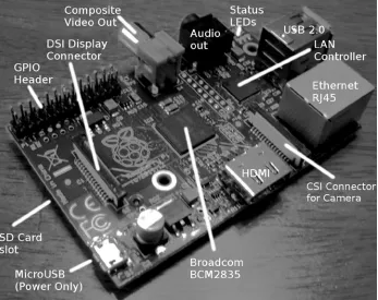
Figure 2-1. Model B interfaces
Table 2-1. Model Differences
Resource
Model A
Model B
RAM 256 MB 512 MB
USB ports 1 2
Ethernet port None 10/100 Ethernet (RJ45)
Power consumption10 300 mA (1.5 W) 700 mA (3.5 W)
Target price9 $25.00 $35.00
As you can see, one of the first differences to note is the amount of RAM available. The revision 2.0 (Rev 2.0) Model B has 512 MB of RAM instead of 256 MB. The GPU also shares use of the RAM. So keep that in mind when budgeting RAM.
In addition, the Model A does not include an Ethernet port but can support networking through a USB network adapter. Keep in mind that only one USB port exists on the Model A, requiring a hub if other USB devices are needed.
Finally, the power consumption differs considerably between the two models. The Model A is listed as requiring 300 mA vs. 700 mA for the Model B. Both of these figures should be considered low because consumption rises considerably when the GPU is active (when using the desktop through the HDMI display port).
7
Hardware in Common
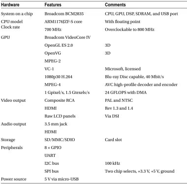
The two Raspberry Pi models share some common features, which are summarized in Table 2-2.9 The Hardware
column lists the broad categories; the Features column provides additional specifics.
Table 2-2. Common Hardware Features
Hardware
Features
Comments
System on a chip Broadcom BCM2835 CPU, GPU, DSP, SDRAM, and USB port CPU model
Clock rate
ARM1176JZF-S core With floating point
700 MHz Overclockable to 800 MHz
GPU Broadcom VideoCore IV
OpenGL ES 2.0 3D
OpenVG 3D
MPEG-2
VC-1 Microsoft, licensed
1080p30 H.264 Blu-ray Disc capable, 40 Mbit/s
MPEG-4 AVC high-profile decoder and encoder
1 Gpixel/s, 1.5 Gtexels/s 24 GFLOPS with DMA
Video output Composite RCA PAL and NTSC
HDMI Rev 1.3 and 1.4
Raw LCD panels Via DSI
Audio output 3.5 mm jack HDMI
Storage SD/MMC/SDIO Card slot
Peripherals 8 × GPIO UART
I2C bus 100 kHz
SPI bus Two chip selects, +3.3 V, +5 V, ground Power source 5 V via micro-USB
Which Model?
One of the questions that naturally follows a model feature comparison is why the Model A? Why wouldn’t everyone just buy Model B?
Power consumption is one deciding factor. If your application is battery powered, perhaps a data-gathering node in a remote location, then power consumption becomes a critical factor. If the unit is supplemented by solar power, the Model A’s power requirements are more easily satisfied.
Unit cost may be critical to students in developing countries. Networking can be sacrificed, if it still permits the student to learn on the cheaper Model A. If network capability is needed later, even temporarily, a USB network adapter can be attached or borrowed.
9
Preparation
While it is assumed that you’ve already started with the Raspberry Pi, there may be a few things that you want to do before working through the rest of this book. For example, if you normally use a laptop or desktop computer, you may prefer to access your Pi from there. Consequently, some of the preparation in this chapter pertains to network access.
If you plan to do most or all of the projects in this book, I highly recommend using something like the Adafruit Pi Cobbler (covered later in this chapter). This hardware breaks out the GPIO lines in a way that you can access them on a breadboard. If you’re industrious, you could build a prototyping station out of a block of wood. I took this approach but would buy the Adafruit Pi Cobbler if I were to do it again (this was tedious work).
Static IP Address
The standard Raspbian SD card image provides a capable Linux system, which when plugged into a network, uses DHCP to automatically assign an IP address to it. If you’d like to connect to it remotely from a desktop or laptop, then the dynamic IP address that DHCP assigns is problematic.
There are downloadable Windows programs for scanning the network. If you are using a Linux or Mac host, you can use Nmap to scan for it. The following is an example session from a MacBook Pro, using the MacPorts collection
nmap command. Here a range of IP addresses are scanned from 1–254:
$ sudo nmap −sP 192.168.0.1−254
Starting Nmap 6.25 (http://nmap.org) at 2013−04−14 19:12 EDT . . .
Nmap scan report for mac (192.168.0.129) Host is up.
Nmap scan report for rasp (192.168.0.132) Host is up (0.00071s latency).
MAC Address : B8:27:EB:2B:69:E8 (Raspberry Pi Foundation)
Nmap done : 254 IP addresses (6 hosts up) scanned in 6.01 seconds $
In this example, the Raspberry Pi is clearly identified on 192.168.0.132, complete with its MAC address. While this discovery approach works, it takes time and is inconvenient.
Using SSH
If you know the IP address of your Raspberry Pi or have the name registered in your hosts file, you can log into it by using SSH. In this example, we log in as user pi on a host named rasp (in this example, from a Mac):
$ ssh pi@rasp pi@rasp’s password:
Linux raspberrypi 3.2.27+ #250 PREEMPT ... armv6l ...
Last login : Fri Jan 18 22:19:50 2013 from 192.168.0.179 $
Files can also be copied to and from the Raspberry Pi, using the scp command. Do a man scp on the Raspberry Pi to find out more.
It is possible to display X Window System (X-Window) graphics on your laptop/desktop, if there is an X-Window server running on it. (Windows users can use Cygwin for this, available from www.cygwin.com.) Using Apple's OS X as an example, first configure the security of your X-Window server to allow requests. Here I’ll take the lazy approach of allowing all hosts (performed on the Mac) by using the xhost command:
$ xhost +
access control disabled, clients can connect from any host $
From the Raspberry Pi, connected through the SSH session, we can launch Xpdf, so that it opens a window on the Mac:
$ export DISPLAY=192.168.0.179:0 $ xpdf &
Here, I’ve specified the Mac’s IP address (alternatively, an /etc/hosts name could be used) and pointed the Raspberry Pi to use the Mac’s display number :0. Then we run the xpdf command in the background, so that we can continue to issue commands in the current SSH session. In the meantime, the Xpdf window will open on the Mac, while the Xpdf program runs on the Raspberry Pi.
This doesn’t give you graphical access to the Pi’s desktop, but for developers, SSH is often adequate. If you want remote graphical access to the Raspberry’s desktop, see the next section, where VNC is introduced.
VNC
If you’re already using a laptop or your favorite desktop computer, you can conveniently access your Raspberry Pi’s graphical desktop over the network. Once the Raspberry Pi’s VNC server is installed, all you need is a VNC client on your accessing computer. Once this is available, you no longer need a keyboard, mouse, or HDMI display device connected to the Raspberry Pi. Simply power up the Pi on your workbench, with a network cable plugged into it.
You can easily install the VNC server software on the Pi at the cost of about 10.4 MB in the root file system. The command to initiate the download and installation is as follows:
$ sudo apt–get install tightvncserver
After the software is installed, the only remaining step is to configure your access to the desktop. The vncserver
11
Using SSH to log in on the Raspberry Pi, type the following command:$ vncserver :1 –geometry 1024x740 –depth 16 –pixelformat rgb565
You will require a password to access your desktop.
Password: Verify:
Would you like to enter a view–only password (y/n ) ? n New 'X' desktop is rasp:1
Creating default startup script/home/pi/.vnc/xstartup Starting applications specified
in/home/pi/.vnc/xstartup
Log file is/home/pi/.vnc/rasp:1.log $
The password prompts are presented only the first time that you start the VNC server.
Display Number
In the vncserver command just shown, the first argument identifies the display number. Your normal Raspberry Pi X-Window desktop is on display :0. So when you start up a VNC server, choose a new unique display number like :1. It doesn’t have to be the number 1. To a limited degree, you can run multiple VNC servers if you find that useful. For example, you might choose to start another VNC server on :2 with a different display resolution.
Geometry
The -geometry 1024x740 argument configures the VNC server’s resolution in pixels. This example’s resolution is unusual in that normally 1024×768 would be used for a display resolution, a common geometry choice for monitors. But this need not be tied to a physical monitor resolution. I chose the unusual height of ×740 to prevent the VNC client program from using scrollbars (on a Mac). Some experimentation may be required to find the best geometry to use.
Depth
The -depth 16 argument is the pixel-depth specification. Higher depths are possible, but the resulting additional network trafficc might curb your enthusiasm.
Pixel Format
The last command-line argument given is -pixelformat rgb565. This particular example specifies that each pixel is 5 bits, 6 bits, 5 bits—for red, green and blue, respectively.
Password Setup
Server Startup
If you often use VNC, you may want to define a personal script or alias to start it on demand. Alternatively, have it started automatically by the Raspberry Pi as part of the Linux initialization. See Chapter 17 for more information about initialization scripts.
VNC Viewers
To access your VNC server on the Raspberry Pi, you need a corresponding VNC viewer on the client side. On the Mac, you can use the MacPorts collection to install a viewer:
$ sudo port install vnc
Once the viewer is installed, you can access your VNC server on the Raspberry Pi at 192.168.0.170, display :1, with this:
$ vncviewer 192.168.0.170:1
If you have your Raspberry Pi in the hosts file under rasp, you can use the name instead:
$ vncviewer rasp:1
When the VNC viewer connects to the server, you will be prompted for a password. This obviously keeps others out of your VNC server.
For Ubuntu Linux, you can install the xvnc4viewer package. For Windows, several choices are available, such as RealVNC and TightVNC.
If you find that the screen resolution doesn’t work well with your client computer, experiment with different VNC server resolutions (-geometry). I prefer to use a resolution that doesn’t result in scrollbars in the viewer. Scrolling around your Raspberry Pi desktop is a nuisance. You can eliminate the need for scrolling by reducing the geometry dimensions.
Stopping VNC Server
Normally, you don’t need to stop the VNC server if you are just going to reboot or shut down your Raspberry Pi. But if you want to stop the VNC server without rebooting, this can be accomplished. Supply the display number that you used in the VNC server startup (:1 in this example) using the -kill option:
$ vncserver –kill :1
This can be useful as a security measure, or to save CPU resources when the server isn’t being used. This can also be useful if you suspect a VNC software problem and need to restart it.
Prototype Station
13
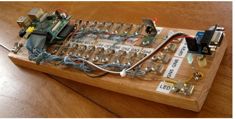
For this reason, I mounted my Raspberry Pi on a nice block of wood. A small plank can be purchased from the lumberyard for a modest amount. I chose to use teak since it looks nice and doesn’t crack or warp. Even if you choose to use something like the Adafruit Pi Cobbler, you may find it useful to anchor the Raspberry Pi PCB. Mount the PCB on the wood with spacers. Figure 3-1 shows my prototype station.Figure 3-1. A simple prototype station
Retro Fahnestock clips were installed and carefully wired to a connector on header strip P1 (the wiring was the most labor-intensive part of this project).
Tip
■
Fahnestock clips can be economically purchased at places like www.tubesandmore.com (part # S-H11-4043-6).
A small PCB for the RS-232 interface was acquired from eBay ($2.32 total) and mounted at the end of the station. Wires from the RS-232 PCB were routed back to RX/TX and +3.3 V clips and simply clipped into place (this allows you to disconnect them, if you wish to use those GPIO pins for some other purpose). The RS-232 PCB is permanently grounded for convenience.The RS-232 PCB is necessary only for those who wish to use a serial console or to interface with some other serial device. The PCB acquired was advertised on eBay as “MAX232CSE Transfer Chip RS-232 To TTL Converter Module COM Serial Board.” The converter (based on the MAX232CSE chip) will work with TTL or 3.3 V interfaces. Connecting the RS-232 converter’s VCC connection to the Raspberry Pi +3.3 V supply makes it compatible with the Pi.
Caution
■
Do not connect the RS-232 converter to +5 V, or you will damage the Pi. For additional information about
this, see Chapter 11.
The LED was added to the station last. It was soldered to a pair of half-inch finishing nails, nailed into the wood. The LED’s cathode has a 220 W resister soldered in series with it to limit the current and wired to ground. The anode is connected to the Fahnestock clip labeled LED. The LED can be tested by connecting an alligator lead from the LED clip to the +3.3 V supply clip (this LED also tolerates +5 V). Be sure to choose a low- to medium-current LED that requires about 10 mA or less (16 mA is the maximum source current from a GPIO pin).
To test your prototyping station, you may want to use the script listed in the “GPIO Tester” section in Chapter 12. That script can be used to blink a given GPIO pin on and off in 1-second intervals.
Adafruit Pi Cobbler
A much easier approach to prototype connections for GPIO is to simply purchase the Adafruit Pi Cobbler kit, which is available from the following site:
learn.adafruit.com/adafruit-pi-cobbler-kit/overview
This kit provides you with these features:
Header connector for the Pi’s P1 •
After assembly, you plug the ribbon cable onto the header P1. At the other end of the ribbon cable is a small PCB that provides 26 pins that plug into your prototype breadboard. A small amount of assembly is required.
Gertboard
Students might consider using a Gertboard, which is available from this site:
uk.farnell.com
The main reason behind this recommendation is that the Raspberry Pi’s connections to the outside world are sensitive, 3.3 V, and vulnerable to static electricity. Students will want to connect all manner of buttons, switches, motors, and relays. Many of these interfaces require additional buffers and drivers, which is what the Gertboard is there for.
In addition to providing the usual access to the Pi’s GPIO pins, the Gertboard also provides these features:
Twelve
• buffered I/O pins Three push buttons •
Six open collector drivers (up to 50 V, 500 mA) •
A motor controller (18 V, 2 A) •
A two-channel 8/10/12 bit digital-to-analog converter •
A two-channel 10-bit analog-to-digital converter •
A 28-pin DIP ATmega microcontroller •
15
Bare Metal
Despite the availability of nice adapters like the Gertboard, the focus of this text is on interfacing directly to the Pi’s 3 V GPIO pins. Here are some of the reasons:
No specific adapter has to be purchased for the projects in this book. •
Any specified adapter can go out of production. •
You’ll not likely use an expensive adapter on each
• deployed Pi.
Bare metal interfacing will exercise your design skills. •
If we were to do projects with only wiring involved, there wouldn’t be much learning involved. Facing the design issues that arise from working with weak 3 V GPIOs driving the outside world will be much more educational.
Power
One of the most frequently neglected parts of a system tends to be the power supply—at least when everything is working. Only when things get weird does the power supply begin to get some scrutiny.
The Raspberry Pi owner needs to give the power supply extra respect. Unlike many AVR class boards, where the raw input voltage is followed by an onboard 5 V regulator, the Pi expects its power to be regulated at the input. The Pi does include onboard regulators, but these regulate to lower voltages (3.3 V and lower).
Figure 4-1 illustrates the rather fragile Micro-USB power input connector. There is a large round capacitor directly behind the connector that people often grab for leverage. It is a mistake to grab it, however, as many have reported “popping it off” by accident.
18
Calculating Power
Sometimes power supplies are specified in terms of voltage, and power handling capability in watts. The Pi’s input voltage of 5 V must support a minimum of 700 mA (Model B). Let’s compute a power supply figure in watts (this does not include any added peripherals):
The 3.5 W represents a minimum requirement, so we should overprovision this by an additional 50%:
P
The additional 50% yields a power requirement of 5.25 W.
Tip
■
Allow 50% extra capacity for your power supply. A power supply gone bad may cause damage or many other
problems. One common power-related problem for the Pi is loss of data on the SD card.
Current Requirement
Since the power supply being sought produces one output voltage (5 V), you’ll likely see adapters with advertised
current ratings instead of power. In this case, you can simply factor a 50% additional current instead:
I I
To double-check our work, let’s see whether this agrees with the power rating we computed earlier:
P = V I = 5 1.05 = 5.25 W
´ ´
The result does agree. You can conclude this section knowing that you minimally need a 5 V supply that produces one of the following:
5.25 W or more •
1.05 A or more (ignoring peripherals) •
Peripheral Power
Each additional circuit that draws power, especially USB peripherals, must be considered in a power budget. Depending on its type, a given USB peripheral plugged into a USB 2 port can expect up to 500 mA of current, assuming it can obtain it. (Pre Rev 2.0 USB ports were limited to 140 mA by polyfuses.)
Wireless adapters are known to be power hungry. Don’t forget about the keyboard and mouse when used, since they also add to the power consumption. If you’ve attached an RS-232 level shifter circuit (perhaps using MAX232CPE), you should budget for that small amount also in the 3 V supply budget. This will indirectly add to your +5 V budget, since the 3 V regulator is powered from it. (The USB ports use the +5 V supply.) Anything that draws power from your Raspberry Pi should be tallied.
Model B Input Power
The Raspberry Pi’s input voltage is fixed at exactly 5 V (±0.25 V). Looking at the schematic in Figure 4-2, you can see how the power enters the micro-USB port on the pin marked VBUS. Notice that the power flows through fuse F3, which is rated at 6 V, 1.1 A. If after an accidental short, you find that you can’t get the unit to power up, check that fuse with an ohmmeter.
20
If you bring the input +5 V power into the Pi through header P1, P5, or TP1, for example, you will lose the safety of the fuse F3. So if you bypass the micro-USB port to bring in power, you may want to include a safety fuse in the supplying circuit.
Figure 4-3 shows the 3.3 V regulator for the Pi. Everything at the 3.3 V level is supplied by this regulator, and the current is limited by it.
Figure 4-3. 3.3 V power
Model A Input Power
Like the Model B, the Model A receives its power from the micro-USB port. The Model A power requirement is 300 mA, which is easily supported by a powered USB hub or desktop USB 2 port. A USB 2 port is typically able to supply a maximum of 500 mA unless the power is divided among neighboring ports. You may find in practice, however, that not all USB ports will deliver 500 mA.
As with the Model B, factor the power required by your USB peripherals. If your total nears or exceeds 500 mA, you may need to power your Model A from a separate power source. Don’t try to run a wireless USB adapter from the Model A’s USB port if the Pi is powered by a USB port itself. The total current needed by the Pi and wireless adapter will likely exceed 500 mA. Supply the wireless adapter power from a USB hub, or power the Pi from a 1.2 A or better power source. Also be aware that not all USB hubs function correctly under Linux, so check compatibility if you’re buying one for that purpose.
3.3 Volt Power
Since the 3.3 V supply appears at P1-01, P1-17, and P5-02, it is useful to examine Figure 4-3 (shown previously) to note its source. This supply is indirectly derived from the input 5 V supply, passing through regulator RG2. The maximum excess current that can be drawn from it is 50 mA; the Raspberry Pi uses up the remaining capacity of this regulator.
When planning a design, you need to budget this 3 V supply carefully. Each GPIO output pin draws from this power source an additional 3 to 16 mA, depending on how it is used. For more information about this, see Chapter 12.
Powered USB Hubs
Again, take into account that not all USB hubs work with (Raspbian) Linux. The kernel needs to cooperate with connected USB hubs, so software support is critical. The following web page lists known working USB hubs:
http://elinux.org/RPi_Powered_USB_Hubs
Power Adapters
This section pertains mostly to the Model B because the Model A is easily supported by a USB 2 port. We’ll first look at an unsuitable source of power and consider the factors for finding suitable units.
An Unsuitable Supply
The example shown in Figure 4-4 was purchased on eBay for $1.18 with free shipping (see the upcoming warning about fakes). For this reason, it was tempting to use it.
Figure 4-4. Model A1265 Apple adapter
This is an adapter/charger with the following ratings: • Model: A1265
• Input: 100–240 VAC • Output: 5 V, 1 A
When plugged in, the Raspberry Pi’s power LED immediately lights up, which is a good sign for an adapter (vs. a charger). A fast rise time on the power leads to successful power-on resets. When the voltage was measured, the reading was +4.88 V on the +5 V supply. While not ideal, it is within the range of acceptable voltages. (The voltage must be between 4.75 and 5.25 V.)
22
Caution
■
Be very careful of counterfeit Apple chargers/adapters. The Raspberry Pi Foundation has seen returned units
damaged by these. For a video and further information, see www.raspberrypi.org/archives/2151.
E-book Adapters
Some people have reported good success using e-book power adapters. I have also successfully used a 2 A Kobo charger.
Best Power Source
While it is possible to buy USB power adapters at low prices, it is wiser to spend more on a high-quality unit. It is not worth trashing your Raspberry Pi or experiencing random failures for the sake of saving a few dollars.
If you lack an oscilloscope, you won’t be able to check how clean or dirty your supply current is. A better power adapter is cheaper than an oscilloscope. A shaky/noisy power supply can lead to all kinds of obscure and intermittent problems.
A good place to start is to simply Google “recommended power supply Raspberry Pi.” Do your research and include your USB peripherals in the power budget. Remember that wireless USB adapters consume a lot of current—up to 500 mA.
Note
■
A random Internet survey reveals a range of 330 mA to 480 mA for wireless USB adapter current consumption.
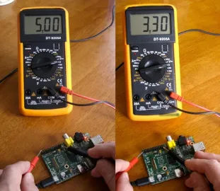
Voltage Test
If you have a DMM or other suitable voltmeter, it is worthwhile to perform a test after powering up the Pi. This is probably the very first thing you should do, if you are experiencing problems.
Follow these steps to perform a voltage test:
1. Plug the Raspberry Pi’s micro-USB port into the power adapter’s USB port. 2. Plug in the power adapter.
3. Measure the voltage between P1-02 (+5 V) and P1-25 (Ground): expect +4.75 to +5.25 V. 4. Measure the voltage between P1-01 (+3.3 V) and P1-25 (Ground): expect +3.135 to +3.465 V.
Caution
■
Be very careful with your multimeter probes around the pins of P1.
Be especially careful not to short the
+5 V to the +3.3 V pin
, even for a fraction of a second. Doing so will zap your Pi! If you feel nervous or shaky about this,
leave it alone. You may end up doing more harm than good. As a precaution, put a piece of wire insulation (or spaghetti)
over the +3.3 V pin.
The right side of Figure 4-5 shows the positive DMM probe moved to P1-01 to measure the +3.3 V pin. Appendix B lists the ATX power supply standard voltage levels, which include +5 ± 0.25 V and +3.3 ± 0.165 V.
Battery Power
Because of the small size of the Raspberry Pi, it may be desirable to run it from battery power. Doing so requires a regulator and some careful planning. To meet the Raspberry Pi requirements, you must form a power budget. Once you know your maximum current, you can flesh out the rest. The following example assumes that 1 A is required.
Requirements
For clarity, let’s list our battery power requirements:
Voltage 5 V, within ± 0.25 V •
Current 1 A •
24
Headroom
The simplest approach is to use the linear LM7805 as the 5 V regulator. But there are some disadvantages:
There must be some headroom above the input voltage (about 2 V). •
Allowing too much headroom increases the power dissipation in the regulator, resulting in •
wasted battery power.
A lower maximum output current can also result. •
Your batteries should provide a minimum input of 5+2 V (7 V). Any lower input voltage to the regulator will result in the regulator “dropping out” and dipping below 5 V. Clearly, a 6 V battery input will not do.
LM7805 Regulation
Figure 4-6 shows a very simple battery circuit using the LM7805 linear regulator. Resistor RL represents the load (the Raspberry Pi).
Figure 4-6. Regulated battery supply
The 8.4 V battery is formed from seven NiCad cells in series, each producing 1.2 V. The 8.4 V input allows the battery to drop to a low of 7 V before the minimum headroom of 2 V is violated.
Depending on the exact 7805 regulator part chosen, a typical heat-sinked parameter set might be as follows: • Input voltage: 7–25 V
• Output voltage: 1.5 A (heat-sinked) • Operating temperature: 125°C
Keep in mind that the amount of power dissipated by the battery is more than that received by the load. If we assume that the Raspberry Pi is consuming 700 mA, a minimum of 700 mA is also drawn from the battery through the regulator (and it could be slightly higher). Realize that the regulator is dissipating additional energy because of its higher input voltage. The total power dissipated by the regulator and the load is as follows:
P P P
The regulator must dissipate the difference between the input and the output voltages (2.38 W). This additional energy heats up the regulator with the energy being given away at the heat sink. Because of this, designers avoid using a high input voltage on linear regulator circuits.
If the regulator is rated at a maximum of 1.5 A at 7 V (input), the power maximum for the regulator is about 10.5 W. If we apply an input voltage of 8.4 V instead of 7, we can derive what our 5 V maximum current will be:
I P
From this, we find that the 8.4 V battery regulator circuit can provide a maximum of 1.25 A at the output, without exceeding the regulator’s power rating. Multiply 8.4 V by 1.25 A to convince yourself that this equals 10.5 W.
DC-DC Buck Converter
If the application is designed for data acquisition, for example, it is desirable to have it run as long as possible on a given set of batteries or charge cycle. A switching regulator may be more suitable than the linear regulator.
Figure 4-7 shows a very small PCB that is about 1.5 SD cards in length. This unit was purchased from eBay for $1.40, with free shipping. At these prices, why would you build one?
26
They are also simple to use. You have + and – input connections and + and – output connections. Feed power in at one voltage and get power out at another voltage. This is so simple that you’ll forgive me if I omit the diagram for it.
But don’t immediately wire it up to your Raspberry Pi, until you have calibrated the output voltage. While it might
come precalibrated for 5 V, it is best not to count on it. If the unit produces a higher voltage, you might fry the Pi. The regulated output voltage is easily adjusted by a multiturn trim pot on the PCB. Adjust the pot while you read your DMM.
The specifications for the unit I purchased are provided in Table 4-1 for your general amusement. Notice the wide range of input voltages and the fact that it operates at a temperature as low as –40ºC. The wide range of input voltages and current up to 3 A clearly makes this a great device to attach to solar panels that might vary widely in voltage.
Table 4-1. DC-DC buck converter specifications
Parameter
Min
Max
Units
Parameter
Min
Max
Units
Input voltage 4.00 35.0 Volts Output ripple 30.9 mA
Input current 3.0 Amps Load regulation ±0.5 %
Output voltage 1.23 30.0 Volts Voltage regulation ±2.5 %
Conversion efficiency 92 % Working temperature –40 +85 °C
Switching frequency 150 kHz PCB size 45×20×12 mm
Net weight 10 g
The specification claims up to a 92% conversion efficiency. Using 15 V on the input, I performed my own little experiment with measurements. With the unit adjusted to produce 5.1 V at the output, the readings shown in Table 4-2 were taken.
Table 4-2. Readings taken from experiment
Parameter
Input
Output
Units
Voltage 15.13 5.10 Volts
Current 0.190 0.410 Amps
Power 2.87 2.09 Watts
From the table we expected to see more power used on the input side (2.87 W). The power used on the output side was 2.09 W. The efficiency then becomes a matter of division:
2 09 2 87 0 728
.
. = .
From this we can conclude that the measured conversion efficiency was about 72.8%.
The power efficiency for this best case scenario amounts to this:
2 09 2 91 0 718
.
. = .
The absolute best case efficiency for the LM7805 regulator is 71.8%. But this is achieved at its optimal input voltage. Increasing the input voltage to 12 V causes the power dissipation to rise considerably, resulting in a 42.5% efficiency (this calculation is left to the reader as an exercise). Attempting to operate the LM7805 regulator at 15.13 V, as we did with the buck converter, would cause the efficiency to drop to less than 33.7%. Clearly, the buck converter is much more efficient at converting power from a higher voltage source.
Signs of Insufficient Power
In the forums, it has been reported that ping sometimes doesn’t work from the desktop (with HDMI), yet works OK in console mode.42 Additionally, I have seen that desktop windows can freeze if you move them (HDMI). As you start to
move the terminal window, for example, the motion would freeze part way through, as if the mouse stopped working. These are signs of the Raspberry Pi being power starved. The GPU consumes more power when it is active, performing accelerated graphics. Either the desktop freezes (GPU starvation) or the network interface fails (ping). There may be other symptoms related to HDMI activity.
Another problem that has been reported is resetting of the Raspberry Pi shortly after starting to boot. The board starts to consume more power as the kernel boots up, which can result in the Pi being starved.43
If you lose your Ethernet connection when you plug in a USB device, this too may be a sign of insufficient power.44
While it may seem that a 1 A power supply should be enough to supply a 700 mA Raspberry Pi, you will be better off using a 2 A supply instead. Many power supplies simply don’t deliver their full advertised ratings.
The micro-USB cable is something else to suspect. Some are manufactured with thin conductors that can result in a significant voltage drop. Measuring the voltage as shown previously in the “Voltage Test” section may help diagnose that. Try a higher-quality cable to see whether there is an improvement.
No Power
If your Pi appears dead, even though power is present at the input, the input polyfuse could have blown. If this was a recent event, allow the unit to cool down. The polymer in the fuse recrystallizes, but this can take several hours. If you think the F3 poly fuse is permanently destroyed, see the Linux wiki page45 for how to test it.
Table 4-3. Hypothetical LM7805 power use
Parameter
Input
Output
Units
Voltage 7.1 5.10 Volts
Current 0.410 0.410 Amps
29
Header Strips, LEDs, and Reset
In this chapter, an inventory of the Raspberry Pi header strips, LEDs, and reset button connections is covered. These are important interfaces from the Pi to the outside world. You may want to use a bookmark for Table 5-3, which outlines the general purpose input/output (GPIO) pins on header strip P1.
Status LEDs
The Model A Raspberry Pi has a subset of the Model B LED indicators because it lacks the Ethernet port. The Model B has three additional LEDs, each showing the network status. Table 5-1 provides a list of LED statuses.
Table 5-1. Status LEDs
LED
Color
Model A
Model B
Comment
ACT Green OK ACT SD card access activity
PWR Red Yes Yes Power supply
FDX Green N/A Yes LAN: Full duplex
LNK Green N/A Yes LAN: Link
100 Yellow N/A 100 Labeled incorrectly on Rev 1.0 as 10M: 10/100 Mbit link
OK or ACT LED
This green LED indicates SD card I/O activity. This active low LED is internally driven by the kernel on GPIO 16 (see the kernel source file bcm2708.c in arm/mach-bcm2708).
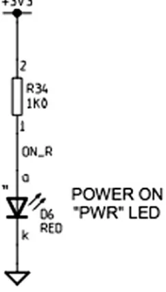
PWR LED
The power LED indicator is not necessarily an indication that the power is good. It simply indicates that power is present. The LED can be lit and still not have sufficient voltage present for the CPU to operate correctly.
If there is any doubt about how good the power supply is, refer to the “Voltage Test” section in Chapter 4, which has information about how to perform a voltage test.
FDX LED
This green LED indicates that the Ethernet port is operating in full-duplex mode.
LNK LED
This green LED indicates that the Ethernet port has an active link-level status.
10M or 10/100 LED
Model B Rev 1.0 had this LED incorrectly labelled as 10M. The correct label is 100, which is found on Rev 2.0 boards. This yellow LED indicates that the 100 Mbit link is active (otherwise, it is a 10 Mbit link).
31
Header P1
The Raspberry Pi includes a 13x2 pin strip identified as P1, which exposes GPIO pins. This includes the I2C, SPI, and UART peripherals as well as the +3.3 V, +5.0 V, and ground connections. Table 5-2 shows the pin assignments for the Model B, Rev 1.0 PCB.
Table 5-2. Rev 1.0 GPIO Header Connector P1 (Top View)
Lower Left
Upper Left
3.3 V power P1-01 P1-02 5 V power GPIO 0 (I2C0_SDA)+R1=1.8k P1-03 P1-04 5 V power GPIO 1 (I2C0_SCL)+R2=1.8k P1-05 P1-06 Ground
GPIO 4 (GPCLK 0/1-Wire) P1-07 P1-08 GPIO 14 (TXD) Ground P1-09 P1-10 GPIO 15 (RXD) GPIO 17 P1-11 P1-12 GPIO 18 (PCM_CLK) GPIO 21 (PCM_DOUT) P1-13 P1-14 Ground
GPIO 22 P1-15 P1-16 GPIO 23 3.3 V power P1-17 P1-18 GPIO 24 GPIO 10 (MOSI) P1-19 P1-20 Ground
GPIO 9 (MISO) P1-21 P1-22 GPIO 25 GPIO 11 (SCKL) P1-23 P1-24 GPIO 8 (CE0)
Ground P1-25 P1-26 GPIO 7 (CE1)
Lower Right Upper Right
Caution
■
The Model A can supply a maximum of 500 mA from the +5 V pins of P1. The model B has a lower
maximum limit of 300 mA. These limits are due to the fusible link F3 on the PCB (shown previously in Figure 4-2 in
Chapter 4). Note also for both models, the +3.3 V pins of P1 and P5 are limited to a maximum of 50 mA. This is the
remaining capacity of the onboard voltage regulator. GPIO currents also draw from this resource. (See Figure 4-3.)
Note
■
Chapter 7 provides more information on identifying your Raspberry Pi. If you have an early pre Rev 2.0 board,
be aware that the GPIO pins differ.
Safe Mode
If your Raspbian SD image supports it, a safe mode can be activated when needed. The New Out of Box Software (NOOBS) image still appears to support this feature.
Pin P1-05, GPIO 3 is special to the boot sequence for Rev 2.0 models. (This is GPIO 1 on the pre Rev 2.0 Model B.) Grounding this pin or jumpering this to P1-06 (ground) causes the boot sequence to use a safe mode boot procedure. If the pin is used for some other purpose, you can prevent this with configuration parameter avoid_safe_mode=1. Be very careful that you don’t accidentally ground a power pin (like P1-01 or P1-02) when you do use it.
Table 5-4. Rev 2.0 P5 Header (Top View)
Lower Left
Upper Left
(Square) 5 V P5-01 P5-02 3.3 V, 50 mA
GPIO 28 P5-03 P5-04 GPIO 29
GPIO 30 P5-05 P5-06 GPIO 31
Ground P5-07 P5-08 Ground
Lower Right Upper Right
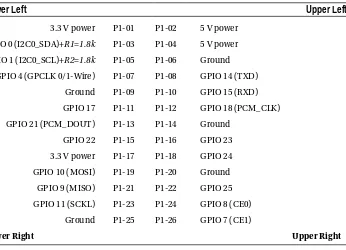
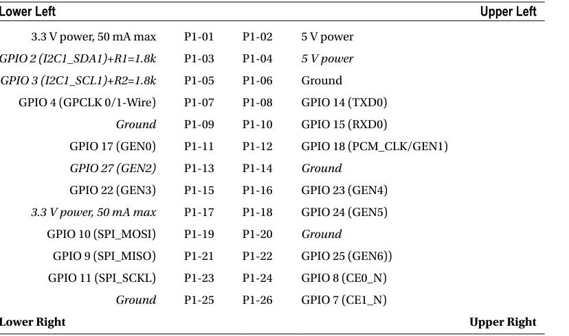
Table 5-3. Rev 2.0 GPIO Header Connector P1 (Top View)
Lower Left
Upper Left
3.3 V power, 50 mA max P1-01 P1-02 5 V power GPIO 2 (I2C1_SDA1)+R1=1.8k P1-03 P1-04 5 V power GPIO 3 (I2C1_SCL1)+R2=1.8k P1-05 P1-06 Ground
GPIO 4 (GPCLK 0/1-Wire) P1-07 P1-08 GPIO 14 (TXD0) Ground P1-09 P1-10 GPIO 15 (RXD0)
GPIO 17 (GEN0) P1-11 P1-12 GPIO 18 (PCM_CLK/GEN1) GPIO 27 (GEN2) P1-13 P1-14 Ground
GPIO 22 (GEN3) P1-15 P1-16 GPIO 23 (GEN4) 3.3 V power, 50 mA max P1-17 P1-18 GPIO 24 (GEN5)
GPIO 10 (SPI_MOSI) P1-19 P1-20 Ground
GPIO 9 (SPI_MISO) P1-21 P1-22 GPIO 25 (GEN6)) GPIO 11 (SPI_SCKL) P1-23 P1-24 GPIO 8 (CE0_N)
Ground P1-25 P1-26 GPIO 7 (CE1_N)
33
If yours fails to respond to safe mode, it may be due to a manufacturing error. See this message:www.raspberrypi.org/phpBB3/viewtopic.php?f=29&t=12007
In that thread, it is suggested that you check the following:
$ vcgencmd otp_dump | grep 30: 30:00000002
If you see the value 2, it means that the firmware thinks this is a Rev 1.0 board (even though it may be a Rev 2.0). When that applies, it will not support the safe mode sequence. Newer Rev 2.0 Pis do not have this issue.
When safe mode is invoked by the jumper, the config.txt file is ignored except for the avoid_safe_mode
parameter. Additionally, this mode overrides the kernel command line, and kernel_emergency.img is loaded. If this file is unavailable, kernel.img is used instead.
The intent of this feature is to permit the user to overcome configuration problems without having to edit the SD card on another machine in order to make a correction. The booted emergency kernel is a BusyBox image with
/boot mounted so that adjustments can be made. Additionally, the /dev/mmcblk0p2 root file system partition can be fixed up or mounted if necessary.
Logic Levels
The logic level used for GPIO pins is 3.3 V and is not tolerant of 5 V TTL logic. The Raspberry Pi PCB is designed to be plugged into PCB extension cards or otherwise carefully interfaced to 3 V logic. Input voltage parameters VIL and VIH are described in Chapter 12. This feature of the Pi makes it an interesting case study as we interface it to the outside world.
GPIO Configuration at Reset
The Raspberry Pi GPIO pins can be configured by software control to be input or output, to have pull-up or pull-down resistors, or to assume some specialized peripheral function. After reset, only GPIO 14 and 15 are assigned a special function (UART). After boot up, however, software can even reconfigure the UART pins as required.
When a GPIO pin is configured for output, there is a limited amount of current that it can drive (source or sink). By default, each P1 GPIO is configured to use an 8 mA driver, when the pin is configured as an output. Chapter 12 has more information on the software control of this.
Note
■
Raspbian 1-Wire bus is GPIO 4 (GPCLK0) Pin P1-07.
1-Wire Driver
The default GPIO pin used for the 1-Wire driver is GPIO 4. This is hard-coded in the following kernel source file:
arch/arm/mach–bcm2708/bcm2708.c
If you need to change this default, alter the line in bcm2708.c that defines the macro W1_GPIO:
#define W1_GPIO 4
Header P5
Be careful with the orientation of this Model B Rev 2.0 header strip. See Figure 5-2: while looking down at P1, with its pin 1 at the lower left, the P5 strip has its pin 1 at the upper left (note the square pad on either side of the PCB).
Figure 5-2. P5’s pin 1 location on the Rev 2.0 Model B
As a practical matter, I found that the pins for P5 can be soldered into the PCB with some care (they are not included). However, the proximity of P5 to P1 makes it impossible to plug in a header connector to P1 and P5 at the same time. With the pins installed, it is possible to use individual wire plugs on the pins as needed. I ended up plugging in a dual-wire plug on P5-04 and P5-06, which is one row away from P1. These wires were then brought out to connectors on a wood strip for easier access.
By default, GPIO pins 28 through 31 are configured for driving 16 mA. (Chapter 12 has more information about this.)
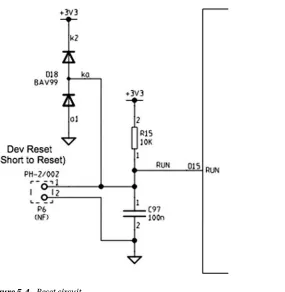
Reset
35
To actuate the reset, P6 pin 1 is short-circuited to P6 pin 2. This resets the BCM2835 SoC chip. This is something you will want to avoid using while Raspbian Linux is up and running. Use reset as a last resort to avoid losing file content.Figure 5-4. Reset circuit
SDRAM
The Model B Rev 2.0 Raspberry Pi has 512 MB of SDRAM, while the older revisions and remaining models have 256 MB. Contrast this to the AVR class ATmega168p, which has 1 KB of static RAM. SDRAM is synchronous dynamic random access memory, which synchronizes with the system bus for improved performance. It uses a form of pipelining to gain this advantage.
There isn’t much about the memory hardware that concerns the average Pi developer. However, in this chapter, you’ll examine some useful Raspbian Linux kernel interfaces that inform us how that memory is utilized. You’ll also examine how to access the memory-mapped ARM peripherals directly from your Linux application.
/proc/meminfo
The pseudo file /proc/meminfo provides us with information about memory utilization. This information varies somewhat by architecture and the compile options used for that kernel. Let’s study an example that is produced by Raspbian Linux, on the Raspberry Pi:
38
All of the memory values shown have the units KB to the right of them, indicating kilo (1,024) bytes. This next example was taken from a Model A Raspberry Pi, with 256 MB:63
$cat/proc/meminfo SReclaimable: 1584 kB SUnreclaim: 2128 kB CommitLimit: 95416 kB Committed_AS: 57876 kB VmallocTotal: 188416 kB VmallocUsed: 704 kB VmallocChunk: 186852 kB
In the sections that follow, a Model B to Model A comparison is provided. In some cases, the comparison isn’t meaningful because the values represent activity that has or has not occurred. For example, the value for AnonPages is going to depend on the mix of commands and applications that have run. But values from both models are provided for completeness. Other values such as MemTotal can be meaningfully compared, however.
MemTotal
The MemTotal line indicates the total amount of memory available, minus a few reserved binary regions. Note that memory allocated to the GPU is not factored into MemTotal. Some may choose to allocate the minimum of 16 MB to the GPU to make more memory available.
Model B
Model A
MemTotal 448,996 KB 190,836 KB
If we break this down a bit further, accounting for memory allocated to the GPU (see Chapter 16 for more details), we find that there is about 9.5 MB (1.9%) of memory that is unaccounted for, as shown in Table 6-1.
Table 6-1. GPU and Main Memory Breakdown
Memory
Model B
Comments
MemTotal 448,996 KB /proc/meminfo
gpu_mem 65,536 KB /boot/config.txt
Total 514,532 KB 502.5 MB
Unaccounted for 9,756 KB 9.5 MB
MemFree
MemFree normally represents the sum of LowFree + HighFree memory in kilobytes on the Intel x86 platform. For ARM, this simply represents the amount of memory available to user space programs.
Model B
Model A
MemFree 340,228 KB 151,352 KB
The Model B has 332.25 MB for application programs, which amounts to about 64.9% (Rev 2.0). The Model A values indicate about 57.7% of the memory is available.
Buffers
This value represents temporary buffers used within the kernel for raw disk blocks, and so forth. This value should not get much larger than about 20 MB or so.27
Model B
Model A
40
Cached
This value represents the read file content that has been cached (page cache). This does not include the content reported for SwapCached.
Model B
Model A
Cached 58,532 KB 20,640 KB
SwapCached
The value shown for SwapCached represents memory that was swapped out and is now swapped back in. For efficiency, these memory pages are still represented by swap disk space, should they be needed again.
Model B
Model A
SwapCached 0 KB 0 KB
The fact that the value is reported as zero is a happy sign that no swapping has occurred, or is no longer pertinent.
Active
The Active memory value represents recently used memory that is not reclaimed, unless absolutely necessary.
Model B
Model A
Active 45,948 KB 14,336 KB
Inactive
This value represents memory that is not active and is likely to be reclaimed when memory is needed.
Model B
Model A
Inactive 51,564 KB 18,648 KB
Active(anon)
This value represents memory that is not backed up by a file and is active. Active memory is not reclaimed unless absolutely necessary.
Model B
Model A
Inactive(anon)
This value represents memory that is not backed up by a file and is not active. Inactive memory is eligible to be reclaimed if memory is required.
Model B
Model A
Inactive(anon) 820 KB 0 KB
Active(file)
This value represents file-backed memory, which is active. Active memory is reclaimed only if absolutely required.
Model B
Model A
Active(file) 21,268 KB 8,868 KB
Inactive(file)
This value represents inactive memory that is backed by a file. Inactive memory is eligible for reclamation, when memory is required.
Model B
Model A
Inactive(file) 50,744 KB 18,648 KB
Unevictable
This amount reflects the total amount of memory that cannot be reclaimed. Memory that is locked, for example, cannot be reclaimed.
Model B
Model A
Unevictable 0 KB 0 KB
Mlocked
This value reports the amount of locked memory.
Model B
Model A
42
SwapTotal
This value reports the total amount of swap space available in kilobytes.
Model B
Model A
SwapTotal 102,396 KB 0 KB
SwapFree
This value reports the remaining amount of swap space available in kilobytes.
Model B
Model A
SwapFree 102,396 KB 0 KB
Dirty
This value represents the kilobytes of memory that have been modified and are waiting to be written to disk.
Model B
Model A
Dirty 0 KB 0 KB
Writeback
This value reports the amount of memory in kilobytes being written back to disk.
Model B
Model A
Writeback 0 KB 0 KB
AnonPages
This represents the non-file-backed pages of memory mapped into user space.
Model B
Model A
AnonPages 24,584 KB 5,348 KB
Mapped
This value reports the files that have been mapped into memory. This may include library code.
Model B
Model A
Shmem
This parameter does not appear to be documented well. However, it represents the amount of shared memory in kilobytes.
Model B
Model A
Shmem 932 KB 136 KB
Slab
This parameter is described as “in-kernel data structures cache.”27
Model B
Model A
Slab 6,088 KB 3,712 KB
SReclaimable
This parameter is described as “Part of Slab that might be reclaimed, such as caches.”27
Model B
Model A
SReclaimable 2,392 KB 1,584 KB
SUnreclaim
This parameter is described as “Part of Slab that cannot be reclaimed [under] memory pressure.”27
Model B
Model A
SUnreclaim 3,696 KB 2,128 KB
KernelStack
This value reports the memory used by the kernel stack(s).
Model B
Model A
KernelStack 1,216 KB 944 KB
PageTables
This value reports the amount of memory required by the page tables used in the kernel. Clearly, with more memory to manage, there is more memory dedicated to page tables.
Model B
Model A
44
NFS_Unstable
This value represents “NFS pages sent to the server, but not yet committed to stable storage.”27 This example data
suggests that NFS is not being used.
Model B
Model A
NFS_Unstable 0 KB 0 KB
Bounce
This reports the memory used for “block device bounce buffers.”27
Model B
Model A
Bounce 0 KB 0 KB
WritebackTmp
This parameter reports the memory used by FUSE for “temporary writeback buffers.”27
Model B
Model A
WritebackTmp 0 KB 0 KB
CommitLimit
The documentation states:
Based on the overcommit ratio (vm.overcommit_ratio
), this is the total amount of memory currently available to be allocated on the system. This limit is only adhered to if strict overcommit accounting is enabled (mode 2 in vm.overcommit_memory). The CommitLimit is calculated with the following formula:
27CommitLimit
= ( vm.overcommit_ratio × Physical RAM) + SwapFor example, a system with 1 GB of physical RAM and 7 GB of swap with a vm.overcommit_ratio of 30 would yield a
CommitLimit of 7.3 GB. For more details, see the memory overcommit documentation in vm/overcommitaccounting. The formula can be written as follows:
C = (R r) + S´
The elements of this formula are described here: • C is the overcommit limit.
• R is the physical RAM available (MemTotal). • S is the swap space available (SwapTotal).
The overcommit ratio, r, is not reported in the /proc/meminfo data. To obtain that ratio, we consult another pseudo file. This example was taken from a Rev 2.0 Model B, but it appears to be a value common to all Pis:
$ cat /proc/sys/vm/overcommit_ratio 50
The value 50 is to be interpreted as r = 0.50 (50%).
Using the overcommit formula, the value for S can be computed for the swap space available:
S = C (R r)
KB
-=
-=
-= ´
´ 326892 448996 0 50 326892 262144 102394
( . )
This fits within 2 KB of the SwapTotal value of 102,396 KB reported by /proc/meminfo.
The overcommit ratio is configurable by the user, by writing a value into the pseudo file. This example changes the ratio to 35%:
$ sudo -i
# echo 35 >/proc/sys/vm/overcommit_ratio # cat /proc/sys/vm/overcommit_ratio 35
The CommitLimit values reported by our example Raspberry Pi sessions are shown in Table 6-2 for comparison purposes. A Model B pre Rev 2.0 version is also included here for comparison.
Table 6-2. Example Model B to Model A Memory Comparisons
Model B Rev 2.0
Model B Pre 2.0
Model A
CommitLimit 326,892 KB 127,868 KB 95,416 KB
MemTotal 448,996 KB 124,672 KB 190,836 KB
SwapTotal 102,396 KB 65,532 KB 0 KB
Commit Ratio 50 50 50
With thanks to Dan Braun for providing the Model B Pre 2.0 data.