Universidade de Aveiro Departamento de Eletrónica,Telecomunicações e Informática 2015
Luís Miguel
Marques Silva
LIMBus: Lightweight monitoring system powered
by iOS and BLE
Universidade de Aveiro Departamento de Eletrónica,Telecomunicações e Informática 2015
Luís Miguel
Marques Silva
LIMBus: Lightweight monitoring system powered
by iOS and BLE
LIMBus: Sistema de monitorização com iOS e BLE
Dissertação apresentada à Universidade de Aveiro para cumprimento dos requisitos necessários à obtenção do grau de Mestre em Engenharia de Com-putadores e Telemática, realizada sob a orientação científica do Doutor José Maria Fernandes, Professor Auxiliar do Departamento de Eletrónica, Teleco-municações e Informática da Universidade de Aveiro, e do Doutor Ilídio Castro
o júri / the jury
presidente / president
Professor Doutor Tomás António Mendes Oliveira e Silva
Professor Associado da Universidade de Aveiro
vogais / examiners
agradecimentos /
acknowledgements
Agradeço toda a ajuda a todos os meus colegas e companheiros, assim como ao meu orientador e co-orientador, sem quem o resultado deste trabalho não teria sido possível. Agradeço também à minha família e à minha namorada
Palavras Chave
bluetooth low energy, message queueing, mqtt, ios, monitorização.Resumo
O advento da Internet das Coisas (IoT) tem levado a uma utilização mais intensa das redes de sensores que incluem tipicamente um nó agregador capaz de (1) comunicar com sensores próximos e (2) encaminhar os dados obtidos para um servidor de retaguarda, recorrendo habitualmente a tecnolo-gias de transporte comuns da Internet. Os smartphones, com uma utilização popular, proporcionam um agente conveniente para implementar o papel de agregador e porta de saída (gateway) dos dados. Quando se estuda as solu-ções existentes neste contexto, verifica-se que a plataforma Android é a mais utilizada, com pouca expressão das soluções baseadas em iOS, apesar da disponibilidade de dispositivos. O desafio neste trabalho é avaliar a utiliza-ção da plataforma iOS para suportar dispositivos com o papel de agregador local e gateway, num cenário de IoT. Importa notar que houve avanços recen-tes na plataforma iOS, sendo agora possível ligar a sensores externos com Bluetooth Low Energy, bem como suportar o tratamento de fluxos contínuos de transmissão (streams). No entanto, ainda não é bem conhecido qual o impacto destas capacidades no desenvolvimento de soluções de redes de sensores e da sua aplicação em cenários reais. Neste contexto, desenvol-vemos o sistema LIMBus, uma solução completa (do sensor à visualização remota) que explora a utilização da plataforma iOS, incluindo a integração de sensores com Bluetooth Low Energy e o envio dos dados para um sistema central, com visualização na Web. O LIMBus utiliza dispositivos com iOS para se ligar a sensores externos por Bluetooth Low Energy, fazendo um uso ex-tenso dos perfis normalizados do Bluetooth Low Energy, e envia os dados dos sensores para o sistema central recorrendo a um protocolo por mensagens. No LIMBus é possível em tempo (quase) real visualizar os dados provenien-tes dos sensores através de uma aplicação Web. O LIMbus foi demonstrado em dois cenários diferentes: um cenário na área da saúde, com a monitori-zação básica de parâmetros fisiológicos, e um cenário na área do combate aos fogos, em que uma câmara térmica, desenvolvida na própria Unidade de investigação, é usada para detetar possíveis focos de calor. O desenvolvi-mento do LIMbus permitiu verificar que o novo suporte do iOS ao Bluetooth Low Energy e aos perfis Bluetooth Low Energy permite uma integração rápida com sensores (capazes de Bluetooth Low Energy) que, aliado a uma soluçãoKeywords
bluetooth low energy, message queueing, mqtt, ios, monitorization.Abstract
Sensor networks are starting to be widespread with the advent of Internet of Things, typically relying on an aggregator that is able to: (1) efficiently commu-nicate with nearby sensors and (2) relay the data to the consumer backoffice usually using Internet friendly protocols. Smartphones, given their pervasive-ness, offer a convenient agent for the role of sensor data gateway. However, when surveying the existing smartphone based solutions Android is the most used, with little expression from iOS based solutions despite their availability. The challenge of this work is to assess iOS as a data aggregator and gate-way solution in a IoT scenario. Recent advances extended iOS and brought new standardized integration with Bluetooth Low Energy sensors and support for sensor streaming handling, but it still remains to be seen what is the im-pact in realistic scenarios and if it allows iOS to be a valuable option. In this context, we propose an end-to-end system, LIMBus, that relies on iOS to in-tegrate a Bluetooth Low Energy based sensor and provides a data gateway to a web connected backoffice. LIMBus uses iOS based handhelds to con-nect to sensors using Bluetooth Low Energy technology with extended use of Bluetooth Low Energy standard profiles, and relays the sensors data stream to a remote backoffice using a message based protocol. Using LIMBus it is possible to review in near real-time data from the sensors or persisted on the backoffice database. LIMBus was demonstrated in two different scenarios: health domain scenario integrating basic physiological monitoring, and a first responder scenario for heat sources localization, using a Bluetooth Low En-ergy compliant thermal sensor integrated in an in-house solution. LIMBus has illustrated that iOS new Bluetooth Low Energy support and Bluetooth Low En-ergy profiles allows a quick integration with Bluetooth Low EnEn-ergy compliantC o n t e n t s
C o n t e n t s
. . . .
i
L i s t o f F i g u r e s
. . . .
iii
L i s t o f Ta b l e s
. . . .
v
Ac r o n y m s
. . . .
vii
1
I n t r o d u c t i o n
. . . .
1
1.1
Overview . . . .
1
1.2
Objectives . . . .
2
1.3
Contributions . . . .
2
1.4
Structure . . . .
3
2
S tat e o f t h e A rt
. . . .
5
2.1
Bluetooth Low Energy . . . .
5
2.1.1
Specification Overview . . . .
5
2.1.2
Bluetooth Low Energy Applications and Sensors . . . .
6
2.2
iOS . . . .
7
2.3
Message Oriented Middleware and MQTT . . . .
9
3
S c e n a r i o s
. . . .
13
3.1
Health Scenario . . . .
13
3.1.1
e-Health module . . . .
14
3.2
Firefighters Scenario
. . . .
16
3.2.1
Thermal Camera . . . .
16
3.2.2
Thermal Camera and BLE
. . . .
16
4
T h e B L E h e a lt h k i t i n t e g r at i o n
. . . .
19
4.1
Introduction . . . .
19
4.2
nRF51-DK . . . .
20
4.3
mbed . . . .
21
4.4
LIMBusEmbedded
. . . .
22
4.4.1
Overview . . . .
22
4.4.2
e-Health Library . . . .
23
5
S y s t e m a r c h i t e c t u r e a n d i m p l e m e n tat i o n
. . . .
25
5.1
System Architecture
. . . .
25
5.1.1
Components interaction . . . .
26
5.1.2
Sensors to aggregator BLE streams . . . .
28
5.1.3
Aggregator to backend messaging . . . .
28
5.2
Implementation . . . .
31
5.2.1
Mobile Application . . . .
31
5.2.2
Messages broker and LIMBusWorker . . . .
35
5.2.3
LIMBusWeb
. . . .
36
5.2.4
Lessons Learned . . . .
37
6
S y s t e m Va l i d at i o n
. . . .
39
6.1
Background Operation . . . .
39
6.2
Bluetooth Low Energy Performance . . . .
43
6.3
Health Scenario . . . .
44
6.4
Firefighters Scenario
. . . .
48
7
C o n c l u s i o n
. . . .
49
7.1
Future Work . . . .
49
R e f e r e n c e s
. . . .
51
ii
L i s t o f F i g u r e s
2.1
GATT-based Profile Hierarchy [4] . . . .
6
3.1
e-Health Shield [55] . . . .
14
3.2
e-Health Sensors . . . .
15
4.1
nRF51-DK coupled with e-Health Shield
. . . .
20
4.2
nRF51-DK [13] . . . .
21
4.3
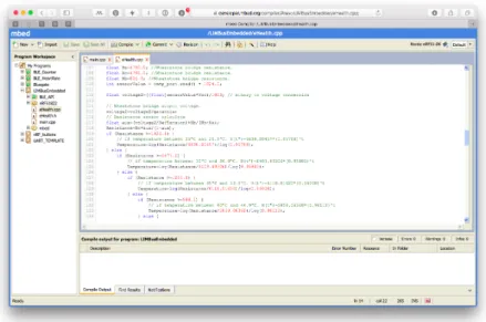
mbed online IDE with the LIMBusEmbedded project . . . .
22
4.4
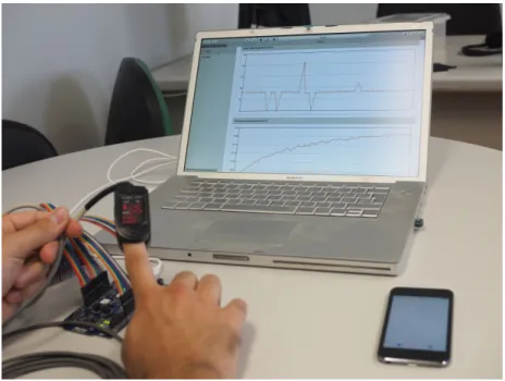
LIMBus hardware in use setup . . . .
23
5.1
LIMBus Architecture – Components interconnection and organization . . . .
26
5.2
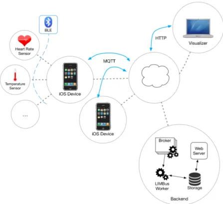
System Interaction Overview . . . .
27
5.3
Server Database Model – Used to store users and BLE information, and sensors data 27
5.4
MQTT Characteristics Message Model . . . .
28
5.5
LIMBusWorker sensor data storage activity diagram . . . .
30
5.6
LIMBus System Components Diagram . . . .
31
5.7
LIMBus for iOS User Interface . . . .
34
5.8
Thermal Camera Screen . . . .
34
5.9
Thermal Camera Temperature Gradient . . . .
35
5.10 LIMBusWeb: Subject Heart Rate and Temperature . . . .
36
6.1
BLE Packet Loss . . . .
44
6.2
Health Scenario: subject being monitored . . . .
45
L i s t o f Ta b l e s
2.1
Bluetooth Low Energy (BLE) Adopted Profiles [20] . . . .
7
2.2
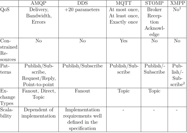
MOM Comparison . . . .
10
3.1
Thermal Camera Characteristics . . . .
17
Ac r o n y m s
ACL Access Control List
ADP Apple Developer Program
AMQP Advanced Message Queuing Protocol
API Application Programming Interface
BLE Bluetooth Low Energy
BR/EDR Bit Rate/Enhanced Data Rate
CoAP Constrained Application Protocol
CORBA Common Object Request Broker Architecture
DCOM Distributed Component Object Model
DDS Data Distribution Service
ECG Electrocardiogram
GATT Generic ATTribute Profile
HTTP Hypertext Transfer Protocol
IDE Integrated Development Environment
IoT Internet of Things
JSON JavaScript Object Notation
MFi Made for iPhone/iPod/iPad
MOM Message Oriented Middleware
MQTT Message Queueing Telemetry Transport
NDA Non Disclosure Agreement
ODB-II On-Board Diagnostics II
P2P Peer-to-peer
QoS Quality of Service
RF Radio Frequency
RMI Remote Method Invocation
RPC Remote Procedure Call
SDK Software Development Kit
SoC System-on-Chip
STOMP Simple Text Oriented Messaging Protocol
TCP Transmission Control Protocol
UDP User Datagram Protocol
UUID Universally Unique Identifier
UART Universal Asynchronous Receiver/Transmitter
XMPP Extensible Messaging and Presence Protocol
c h a p t e r
1
I n t r o d u c t i o n
1.1
overview
The general availability of internet access and the ubiquitous use of smart personal devices, namely smartphones, raise the feasibility of new mobile applications, targeting connected scenarios.
This global communication system enabled the development of remote monitoring solutions in a cost effective way. Scientists can monitor the environment of remote locations without the need for a physical presence, allowing a better measurement and understanding of the natural phenomena. By remote monitoring their operations, industries can optimize them, decreasing costs and increasing performance.
People can make decisions about their lives based on information that is produced remotely by their smart appliances too. For example, with smart refrigerators, people can be notified if they are running low on some product, allowing them to make a small detour on their way home to buy it. But maybe more important is the use of these new monitoring systems for health applications, the so called mHealth (mobile health) [1]. mHealth has the potential to dramatically reduce healthcare costs, either by prevention [2] or by giving healthcare professionals the means to remotely monitor and give feedback to patients [3], thus reducing the number of visits by the patient to the hospital or clinic.
BLE [4] is a recent technology from the Bluetooth SIG that was designed with low cost and energy efficiency in mind and allows devices to communicate within a distance of a few meters, from months to years [5], using a small button cell battery, making it suitable for this emerging market.
The use of mobile devices as gateways for data collected by sensors has been widely acknowledged, including in the health domain [6] [7] [8] [9]. For this purpose, the usage of Android based solutions with Bluetooth Bit Rate/Enhanced Data Rate (BR/EDR) (version < 4.0) (referred sometimes as Classic Bluetooth) is higher, than the usage of iOS with BLE. Although no comparative survey could be found, the search results in the literature support this difference. Further, the iOS based solutions usually require some sort of interaction from the user for the data to be uploaded (or that the application be running in foreground), due to the backgrounding restrictions present in iOS [10] [11]. The substantial market penetration of iPhones, and iOS in general, favours the opportunity to use these as gateways to provide the necessary connectivity for sensors data to be streamed to the
cloud. The evolution of Bluetooth in iOS, with support of BLE, and the introduction of background functionality for applications suggests that some of the hurdles for iOS adoption in sensor systems may have been overcome. This dissertation will assess if the new BLE iOS framework and background modes provide suitable support for using the iOS system as both a sensor data aggregator and as a data gateway in sensor networks.
1.2
objectives
There is a large market penetration of iOS devices that support BLE, with some estimates pointing to 94% of the iPhones currently being used and 71% of the iPads [12]. This presents an opportunity to explore these devices as energy-efficient and BLE compliant data-gathering gateways. With this in mind, the LIMBus system, leverages the BLE capabilities, which allows an iPhone or iPad to act as a gateway for data being acquired by nearby sensors, to be remotely visualized.
The main objectives of this work are:
• Explore BLE profiles instead of traditional Peer-to-peer (P2P) Bluetooth BR/EDR socket stream and explore the new Application Programming Interface (API) in iOS
• Develop an iOS based gateway solution to relay data acquisition from BLE compliant sensors to web clients
• Use a decoupled solution between iOS gateway and sensor data consumers
• Illustrate the system in two realistic scenarios with different types of sensors: a health monitoring scenario and a temperature monitoring solution
1.3
contributions
The main contributions of LIMBus (Lightweight iOS Monitoring middleware) are:
• LIMBusCore – An iOS library that manages the BLE profile based connections with sensors and data acquisition.
• LIMBusTransmission – An iOS library that relays the data to online clients on the web. The solution relies on a messaging broker to manage the data exchange between LIMBusTransmission and the client – decoupling the library from transport related concerns.
• A BLE compliant interface for e-Health kit used in the health scenario – although not the main focus, this result implied a “low level” integration from the existing sensing solution with a BLE board, the nRF51-DK [13] – resulting in the port of the original e-Health library [14] to the mbed platform.
• LIMBus for iOS – An iOS application, gateway for BLE compliant sensors.
• LIMBusWeb – A web client for visualization of the relayed sensor data.
• Thermal Camera – a component for the decoding and visualization of temperature data from the thermal camera sensor.
• A publication in Mobiquitous – LIMBus: a lightweight remote monitoring system powered by iOS and BLE [15]
1.4
structure
This dissertation is comprised of seven chapters:
• Chapter 1: Introduction – This chapter describes the context of this dissertation, its objectives and contributions.
• Chapter 2: State of the Art – This chapter reviews the iOS platform, the Bluetooth Low Energy technology and Message Oriented Middleware.
• Chapter 3: Scenarios – This chapter describes the scenarios which where used to test and validate this work and their requisites.
• Chapter 4: The BLE Health Kit Integration – This chapter describes the work done to integrate the e-Health Kit sensors into a Bluetooth Low Energy compliant sensor.
• Chapter 5: System Architecture and Implementation – This chapter presents the system architecture and describes its implementation.
• Chapter 6: System Validation – This chapter presents results of the system.
• Chapter 7: Conclusion – This chapter discusses the results, reviews the work done and suggests some future work.
c h a p t e r
2
S tat e o f t h e A rt
This chapter presents a review of the Bluetooth Low Energy technology and the iOS platform, taking into consideration the objectives of this work. Although messaging is not an objective of this work, it influenced some decisions on the architecture. Because of this, a revision of Message Oriented Middleware is also included.
2.1
bluetooth low energy
Development of what would become the Bluetooth Low Energy technology was started in 2001 by researchers at Nokia [16]. The objective was to develop a technology, based on the already established Bluetooth technology, that would consume less power and be less expensive [17]. In 2006 the technology became public under the name Wibree [17] and in 2007, after negotiations with the Bluetooth SIG, an agreement was reached to include Wibree on the Bluetooth specification under the name Bluetooth Low Energy, the new specification (version 4.0) was completed in 2010 [18].
In the new specification, a BLE device can be single-mode or dual-mode. A single-mode device can only communicate with other BLE devices. A dual-mode device can communicate with both Bluetooth Low Energy and Bluetooth BR/EDR devices. This distinction is needed because the Low Energy and BR/EDR are not compatible, due in part to the changes made to the Physical Layer and packet format in order to reduce power consumption. Still, part of the hardware stack can be shared (e.g., the radio and antenna).
2.1.1
specification overview
The definition of how two devices exchange data is done by Generic ATTribute Profile (GATT) and GATT transactions are, in turn, defined by high-level concepts: Profiles, Services, Characteristics and Descriptors.
A profile defines a structure of elements such as services and characteristics used to fulfill a certain use case. The profile itself does not appear on a BLE device, only its composing elements. The Bluetooth SIG has adopted several standard profiles in the BLE specification – and continues to adopt more (e.g., Automation IO, Proximity Profile 1.1) – that describe and define common uses of the technology.
Such standard profiles include support for devices that measure the heart rate, the blood glucose level or the weight, and can be accessed and visualized on the Bluetooth Developer Portal [19]. It is with these profiles that manufacturers of hardware and developers of software can ensure the technical compatibility of their products with others.
Each component of a profile is identified using a Universally Unique Identifier (UUID) and has a relationship as represented in figure 2.1:
• Service: a meaningful collection of characteristics and/or relationships to other services used to accomplish a certain function.
• Characteristic: is a value with properties and information about how it can be accessed and how the value can be interpreted/displayed.
• Descriptor: attribute that can be included in a characteristic to help describe a characteristic value, i.e., how it can be interpreted/displayed.
Figure 2.1: GATT-based Profile Hierarchy [4]
2.1.2
bluetooth low energy applications and sensors
There are numerous applications of the BLE technology ranging from consumer electronics to industrial. The Bluetooth SIG alone has adopted several profiles (as seen in Table 2.1) and each company can develop its profiles as needed.
In health and fitness we find not only activity trackers as the Fitbit [21] or heart rate monitors as the Wahoo Blue Heart Rate Monitor [22], but also research initiatives trying to take it to another level by developing an Electrocardiogram (ECG) monitor [23].
ANP
Alert Notification Profile
AIOP
Automation IO Profile
BLP
Blood Pressure Profile
CGMP
Continuous Glucose Monitoring Profile
CPP
Cycling Power Profile
CSCP
Cycling Speed and Cadence Profile
ESP
Environmental Sensing Profile
FMP
Find Me Profile
GLP
Glucose Profile
HOGP
HID over GATT Profile
HRP
Heart Rate Profile
HTP
Health Thermometer Profile
IPSP
Internet Protocol Support Profile
LNP
Location and Navigation Profile
OTP
Object Transfer Profile
PASP
Phone Alert Status Profile
PXP
Proximity Profile
PLXP
Pulse Oximeter Profile
RSCP
Running Speed and Cadence Profile
ScPP
Scan Parameters Profile
TIP
Time Profile
WSP
Weight Scale Profile
Table 2.1: BLE Adopted Profiles [20]
There are however other less obvious applications that show the range of use cases this technology has; a study on the BLE potential for vehicular applications developed a small example for a keyless system [24]. A keyless system is used to unlock a vehicle whenever the owner is near, something that is usually achieved using Radio Frequency (RF) technology. By using the BLE technology, the energy consumption in the key can be reduced, while maintaining the usability of the system.
2.2
ios
iOS is Apple’s operating system that currently runs on the iPhone / iPad / iPod. It was introduced in 2007 with the launch of the iPhone [25], albeit at the time it had not yet been named iOS. This operating system has its roots on Apple Mac OS X [25] [26], and it is Darwin based and Unix-like. Only after the 2nd major release (version 2.0), and the introduction of the App Store, did it gain support for third party applications to be installed by the general public [27].
For third party applications to be created, Apple made available a public version of the iOS Software Development Kit (SDK) [28] and the Integrated Development Environment (IDE) Xcode [29]. The SDK contains all the frameworks and libraries needed to create an application. Xcode comes with a collection of tools which enable developers to debug, test and profile the applications they are creating
[30].
Up until recently, developers that were not enrolled in the Apple Developer Program (ADP) could only test their applications on the iOS Simulator, a tool that comes with Xcode. To deploy and test the applications on a physical device (iPhone/iPad/iPod) an enrolment in the ADP was required, which incurred in costs – this membership did however also include the option to publish the application in the App Store and access to the latest versions of iOS (betas) [31].
Since Jun 2015 [32], Apple merged all its ADP’s (iOS, OS X, watchOS, Safari and, more recently, tvOS) into one single program and, with the new program, anyone can develop and test applications on a physical device, only requiring the paid membership to publish applications in the App Store [33]. When the iPhone 4S was released, it was the first smartphone to be shipped with support for the new and fresh BLE [34] and, with it, a new freedom came to iOS and developers of hardware, either hobbyists or professional. Previously, the communication with external accessories, either via Bluetooth BR/EDR or the “iDevice” (iPhone/iPad/iPod) connector, was limited to those developed under the Made for iPhone/iPod/iPad (MFi) program [35], a licensing program for developers of hardware and software of accessories [36]. This program requires a special request to Apple and most of it is under a Non Disclosure Agreement (NDA) [35].
With the advent of BLE, the CoreBluetooth framework [37] was introduced (iOS 5 [38]) and, with it, support for the development of applications that interact with BLE devices. This framework provides access to the BLE hardware in an iOS device and the functionality for applications to discover and interact with BLE devices.
To develop BLE devices, it is no longer required to be a member of the MFi program [35], so anyone can develop accessories that communicate with iOS applications using BLE. Initially the CoreBluetooth framework provided support for applications to communicate with BLE enabled devices (designated peripherals, in BLE terminology), such as heart rate monitors, thermometers, weight scales, etc. Since iOS 6, this framework also allows that an application acts as a peripheral [39], producing data for other devices to consume [40]. Currently, the CoreBluetooth framework allows an application to assume the central role (client), enabling it to discover, explore and interact with peripheral devices (servers, those who produce data) or to assume the peripheral role (producing data for a central device to consume) [41]. The mix of BLE with mobiles exploded the "appcessories" (accessories with a companion application) world. Fitbit [21] is a well known "appcessory" that makes use of the BLE technology in iOS. It keeps track of the steps taken and overall activity of a person and has a companion application that connects to it, using the BLE technology, and displays the data gathered by the Fitbit in a visually rich form, enabling a better understanding of it by the user. This application also allows this data to be saved to the cloud, making it accessible to the user anywhere [42].
Another example of this sensor cloud connectivity through an iPhone is the Automatic Adapter [43], it connects to the car central computer, using the On-Board Diagnostics II (ODB-II) port, and using BLE sends data from the car computer to the iPhone, which uploads it to the cloud. This enables a user to better understand fuel consumption, track their car and, also, discover possible problems with the car. The backgrounding capabilities (i.e., the functionality when the application is not in the foreground) of iOS applications had always been restricted until iOS 4. In iOS 4, three background modes were introduced: Audio, VoIP and Location. With these modes, applications could play media while in the
background (e.g., music players), receive and sustain voice over IP phone calls or receive GPS location updates.
In iOS 5, and with the introduction of the CoreBluetooth framework, three new background modes were introduced: Newsstand Content, External Accessory and Bluetooth Central [44]. Of these three, the Bluetooth Central mode is the most important given the nature of this work. This mode added the ability for applications to communicate with BLE devices while in the background. Meaning that an application can discover, explorer and push or pull data from a BLE device, while on background. There are some limitations to these communications while the application on background but they are mostly related to priority and the speed what which the BLE scans are performed [45].
The open support of BLE gives iOS developers the chance to test new ideas with hardware devices without having to make a considerable financial commitment. In a world where more and more devices are gaining connectivity, this gives the developers and iOS a chance to play a significant part in the Internet of Things (IoT) revolution.
2.3
message oriented middleware and mqtt
From the start, using a messaging solution was a basic requirement on the system to ensure an easy integration with existing solutions used in the group [46]. For the communication of distributed applications, traditionally developers had to design and implement custom protocols that would be used over TCP/IP. This is a time consuming task and prone to errors.
With the creation of Remote Procedure Calls (RPCs) and, sub-sequentially, other similar systems, as Common Object Request Broker Architecture (CORBA), Distributed Component Object Model (DCOM) and Java Remote Method Invocation (RMI), a higher level of abstraction was introduced which allows applications to perform operations across different system platforms by invoking a local procedure or method. The logic to perform the remote call is abstracted from the developer and happens “behind the scenes”. As with traditional calls to procedures or methods, in these systems, the caller of a procedure or method is required to block and wait until a response is obtained and, as such, to achieve parallelism, multi-threading must be used, which adds to the complexity of the applications and dramatically increases the number of possible problems. Another requirement is that to use RPCs, both the client and the server need to be online simultaneously, which in many cases might not be a desirable constraint when developing the applications, since it requires more logic to handle those edge cases and introduces more complexity and possible errors.
Message Oriented Middleware (MOM), by being decoupled and asynchronous by nature, provides a solution to the problems described above. MOM creates an abstraction of a message queue over the network and is generalization of the “the mailbox” operating system construct.
MOM provides a decoupled layer which allows applications to communicate by sending messages to each other using a central actor (broker) and decouples dependencies on programming data structures needed in the procedure-call approaches. There is no requirement for applications to be simultaneously online, the broker will store the message and deliver it when possible. Historically speaking most MOM implementations were closed source, but recently some open source protocols and implementations were
introduced: Advanced Message Queuing Protocol (AMQP), Data Distribution Service (DDS), Simple Text Oriented Messaging Protocol (STOMP), Extensible Messaging and Presence Protocol (XMPP), Message Queueing Telemetry Transport (MQTT) (Table 2.2).
AMQP
DDS
MQTT
STOMP
XMPP
QoS
Delivery,
Bandwidth,
Errors
+20 parameters
At most once,
At least once,
Exactly once
Broker
Recep-tion
Acknowl-edge
No
1Con-strained
Re-sources
No
No
Yes
No
No
Pat-terns
Publish/Sub-scribe,
Request/Reply,
Point-to-point
Publish/Subscribe
Publish/Sub-scribe
Publish/-Subscribe
Pub-
lish/-
Sub-scribe
2Ex-change
Types
Fanout, Direct,
Topic
Fanout
Topic
Topic
Scala-bility
Dependent of
implementation
Implementation
requirements well
defined in the
specification
-
-
-Table 2.2: MOM Comparison
The AMQP is an open standard that started being developed around 2003, it is designed to support different programming environments and operating systems by having a hard set of rules and behaviours of how it is expected to work [48]. It supports a number of different messag-ing patterns: asynchronous directed messagmessag-ing, request/reply, publish/subscribe, store and forward [49]. The DDS is a Machine-to-Machine (M2M) publish/subscribe standard that is highly scalable and flexible [50].
STOMP is a text based publish/subscribe protocol. It was designed with simplicity and interop-erability in mind and has a frame based protocol modelled on Hypertext Transfer Protocol (HTTP) [51]. XMPP is communication protocol based on XML mainly developed for instant messaging and presence [52]. It has extensions that give it publish/subscribe functionality [47].
1Only through the use of extensions.
2Using the ’XEP-0060: Publish-Subscribe’ [47] extension.
10
MQTT is an open source, lightweight and simple, Client Server publish/subscribe messaging protocol [53].
Considering that our focus is in iOS, a major concern was on iOS support of the messaging solution. After a survey and some technical trials, MQTT showed to be the better option due to the very good support of the MQTT protocol provided by the MQTTKit library [54].
In MQTT protocol, as in other message queueing protocols, a message broker is needed. This broker receives messages published by clients and distributes it to other clients that have subscribed to them. To identify where the messages are to be sent and whom should receive them the concept of topic is used. A topic is a simple string much like a directory path in any *nix system, e.g., /this/is/a/mqtt/topic, /house/room/sensor. This organization allows a client to subscribe to the root of a topic (i.e., /house) and receive messages sent to all its subtopics.
MQTT has a Quality of Service (QoS) feature with 3 levels in increasing complexity, bandwidth and processor usage:
• QoS 0 – At most once delivery: no quality of service is assured by MQTT; the messages will be transmitted in a best effort mode in which the transport layer Transmission Control Protocol (TCP) is the only assurance.
• QoS 1 – At least once delivery: the message is assured to be delivered at least once, there can be duplicated messages.
c h a p t e r
3
S c e n a r i o s
For requirements elicitation and validation of the work, two scenarios were selected: a health scenario and a firefighters scenario. In the health scenario, a subject’s biometric data is continuously read and streamed to a server, allowing the remote monitoring of the subject physiological signals. The thermal camera scenario consists of an infrared sensor camera to be used by firefighters to analyse the ground temperature and help determine if a fire is extinct.
3.1
health scenario
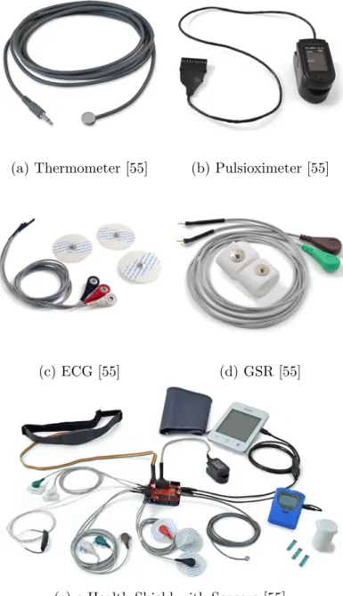
The health scenario is a physiological monitoring scenario. In this scenario, a subject heart rate and temperature is remotely monitored using a pulsioximeter attached to a subject’s finger and a thermometer placed in between the thumb and the index finger. For this scenario the e-Health kit [55] was chosen, which supplies multiple sensors including the pulsioximeter and thermometer. This scenario tries to simulate a use case where a patient has permission to leave the hospital (e.g., someone who had a heart problem) but is required to keep track of certain biometrics signals, allowing these signals to be gathered automatically and periodically.
The heart rate and temperature values read from the sensors are sent to the smartphone application. The application displays those values and uploads them to the server so that they can be visualized remotely.
3.1.1
e-health module
Figure 3.1: e-Health Shield [55]
The e-Health shield (part of the e-Health Kit) is a board (figure 3.1) that has inputs for several sensors, such as: thermometer (figure 3.2a), pulsioximeter (figure 3.2b), electrocardiogram (ECG) (figure 3.2c), Galvanic Skin Response Sensor (GSR) (figure 3.2d), and more. This board then exposes the sensor data using a pin connector that is compatible with the Arduino boards (and can also be used with Raspberry Pi by using the companion adapter).
An "off-the-shelf" sensor-device with Bluetooth Low Energy capabilities could have been used, but given its high cost and given that there was already available an Arduino/Raspberry Pi sensor kit that could be adapted and used for this purpose, the already available Cooking Hacks e-Health sensors module was chosen.
The e-Health module is a hub which gathers several sensors terminals and provides an uniform access to their values. This module is coupled with the nRF51-DK, which provides the necessary programming and BLE functionality.
(a) Thermometer [55]
(b) Pulsioximeter [55]
(c) ECG [55]
(d) GSR [55]
(e) e-Health Shield with Sensors [55]
Figure 3.2: e-Health Sensors
e-health library
The e-Health module comes with a library that converts its physical sensors electric signals into a more usable information, e.g., temperature in Celsius or heart rate in BPM. This library does all the calculations necessary to convert the electric signals coming from the sensors terminals into meaningful and easily accessible data.
3.2
firefighters scenario
This scenario builds on the work being developed in the context of the VitalResponder project [56]. In this scenario, large amounts of data (in the BLE context) are streamed in real-time from the sensor to the smartphone application. It consists in using a thermal sensor device, being developed, as a way for firefighters to analyse the ground of a burned area while searching for hidden fire spots. After a fire is extinct, usually there are spots where some biological material (e.g., tree roots) keeps burning under the ground. To terminate these burning spots, the firefighters do a visual inspection of the ground, looking for signals of fire. The goal of this thermal camera is to enable firefighters to see, in a deterministic way (i.e., view the temperature in Celsius degrees), the ground temperature and determine more accurately if it is a fire spot.
3.2.1
thermal camera
The thermal camera sensor (Figure 3.3a) was developed in-house in a M.Sc. dissertation. It is currently in the prototype stage and has no ready-to-use library available. It has a sensor (Figure 3.3b) with 64 photocells, each produces a value with a range between -50,00oC and 300,00 oC. To transmit
this value, it first converts it into an integer. Multiplying it by 100, thus removing the floating-point decimal component, the number is transformed into a 16-bit integer which can be sent using a BLE characteristic.
(a) Thermal Camera Prototype Board
(b) Infrared Sensor
3.2.2
thermal camera and ble
To increase the efficiency of the transmissions, values from multiple photocells are grouped and sent over the same characteristic. These groups consist of 10 values because of limitations of the hardware, which can only send 20 bytes per characteristic in each transmission. 7 characteristics, with consecutive UUIDs, are used to transmit this data (see Table 3.1). The characteristics values are read periodically (200 milliseconds); after being read the value of each photocell is decoded and displayed in a 64 squares matrix (4x16). Each of these squares is coloured according to the temperature value it represents. Using a range of colours following the HUE format, going from dark blue (coldest) to hot red (hottest).
UUID
Photocells
E7880001-5E76-40E8-B49D-23F21B69A9F2
0 - 9
E7880002-5E76-40E8-B49D-23F21B69A9F2
10 - 19
E7880003-5E76-40E8-B49D-23F21B69A9F2
20 - 29
E7880004-5E76-40E8-B49D-23F21B69A9F2
30 - 39
E7880005-5E76-40E8-B49D-23F21B69A9F2
40 - 49
E7880006-5E76-40E8-B49D-23F21B69A9F2
50 - 59
E7880007-5E76-40E8-B49D-23F21B69A9F2
60 - 63
c h a p t e r
4
T h e B L E h e a lt h k i t
i n t e g r at i o n
4.1
introduction
Enabling the e-Health kit with BLE capabilities was necessary to fulfill the proposed health scenario. Although not the main focus of this thesis, it implied a non trivial and time consuming integration of the e-Health hardware with a BLE hardware interface. Such interface does not exist (as used in our solution) and can be considered a side relevant contribution of the system; this result is referred as LIMBusEmbedded.
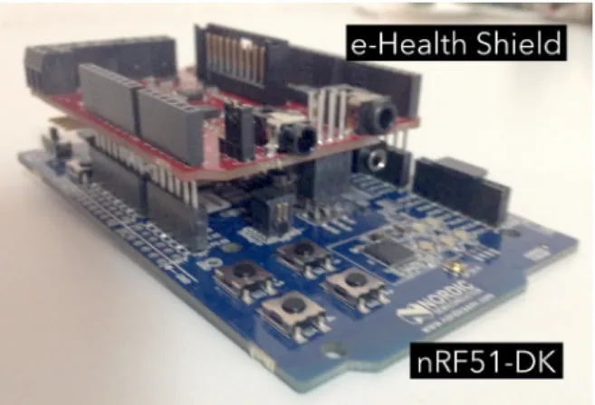
To create a BLE profile based compliant sensor for the health kit, we needed to integrate it with a board that provided such functionality. The nRF51-DK has a chip with an integrated BLE modem, the so called System-on-Chip (SoC), and provided a good choice. It has a pin format that makes it directly compatible with the health kit module (as seen in Figure 4.1) and is supported in the mbed platform [57]. The nRF51-DK makes possible the exposure of the health kit data through a BLE interface and, the mbed platform makes it easier to create such interface by providing a high level abstraction of the microcontroller and modem of the nRF51-DK. The e-Health kit module is connected to the nRF51-DK, which enables the data coming from sensors terminals to be passed onto the nRF51-DK and using the e-Health library is decoded so that it can be processed and exposed using the correct BLE profiles.
Figure 4.1: nRF51-DK coupled with e-Health Shield
4.2
nrf51-dk
The nRF51-DK was chosen because of its very good BLE capabilities and because its board format is similar to that of an Arduino, which enables it to be coupled with Arduino compatible modules, as is the case of the e-Health module.
This board, being mbed enabled, brings to the table a great advantage: it enables rapid prototyping by taking care of the burden of implementing all the low level microcontroller details, much like the Arduino.
Unlike the Arduino platform, mbed gives full access to the boards hardware while still providing an easier entry-point for development of embedded software. In this case in particular there was the need to create a device with a Heart Rate Profile and Health Thermometer Profile, something that would not be possible with the Arduino platform because all its the BLE modules are “too” abstracted and have a certain way of being used, not allowing the creation of services or characteristics, either standard or custom. All the modules found come with a preconfigured Universal Asynchronous Receiver/Transmitter (UART) style service (a characteristic to write and a characteristic to read) that is used as a virtual socket to exchange packets. Though this would be sufficient to create a sensor device that would expose data via BLE, it would not comply with the standard way of exposing the data established by the Bluetooth SIG and the device would not be generic, used only for the purpose of this work.
Figure 4.2: nRF51-DK [13]
4.3
mbed
The ARM mbed is a platform for IoT that provides cloud services, tools and an ecosystem for developers to create IoT devices. It can be thought of as Arduino on steroids. It is programmed using C++ and has an online IDE (figure 4.3) with integrated version control which allows people to work in the same project more easily than Arduino.
The online IDE takes care of compiling and generating the program binary file. When a mbed board is connected to a computer it mounts itself as a flash pen. To program the board a simple drag and drop operation of the downloaded program binary file into this pen starts the flashing process.
mbed provides high level abstractions over the compatible boards while also allowing direct ac-cess to its hardware. In this aspect, Arduino seems to make it harder to acac-cess the underlying hardware.
A great aspect of this platform is that the boards use modern chips which work with 3 and even 1.8 Volts (versus the Arduino 5 Volts old microcontrollers), which enables the development of really low energy devices. This platform also allows a smoother transition from prototype to production than the Arduino platform, since the generated program binary files are ready to flash, which means that there is no requirement for the chip to be previously provisioned with a boot-loader. On top of that, the boards provide access to a JTAG port which enables step by step debugging.
Figure 4.3: mbed online IDE with the LIMBusEmbedded project
4.4
limbusembedded
4.4.1
overview
Using the mbed platform and its BLE library (BLE_API), the device exposes 3 services (Heart Rate Service, Health Thermometer Service, Device Information Service).
An instance of BLEDevice is used to control the BLE functionalities of the the device and this object is responsible for all BLE operations.
To create the services, an instance of HeartRateService, HealthThermometerService and DeviceIn-formationService, respectively, is created. These instances are then passed to the BLEDevice before it starts advertising its services.
The program then enters an infinite loop in which the values of the heart rate and temperature sensors are read and published. The temperature value is read from the sensor using the e-Health library method getTemperature(), which returns the temperature in Celsius.
The Temperature Measurement characteristic is then updated using the updateTemperature(float) method in the HealthThermometerService object instance. The heart rate measurement works a bit differently. The eHealth library continuously (with a certain frequency) reads the heart rate values from the pulsioximeter and stores them in a public variable named BPM. This program then reads the value present in that variable and, using the method updateHeartRate(int) of the HeartRateService object instance, updates the Heart Rate Measurement characteristic.
Figure 4.4: LIMBus hardware in use setup
4.4.2
e-health library
Although the e-Health module can be easily attached to the nRF51-DK, its signal processing library only has support for Arduino or Raspberry Pi, there is no mbed compatible library. Because of that, a partial port of the library had to be made before the e-Health module could be used. The port consisted mainly of correcting the board pins mapping, but also the readjustment of the frequency at which the pulsioximeter sensor is read from. It is suspected that this readjustment was needed because of differences between the Arduino boards and the nRF51-DK.
It was also detected that some noise was introduced into the readings from the pulsioximeter, because of this a simple filter was added. This filter works by ignoring the BPM values for which the magnitude of change from the last value is greater than 10. Although not perfect this filter eliminated most of the noise coming from the sensor.
c h a p t e r
5
S y s t e m a r c h i t e c t u r e a n d
i m p l e m e n tat i o n
5.1
system architecture
The objective of this dissertation was the exploratory use of the iOS platform and BLE technology, to implement a sensor’s data aggregator and gateway, with a decoupled architecture, that enables the remote monitoring using BLE enabled sensors. The proposed solution is the LIMBus system.
The main components of LIMBus are (1) a mobile data aggregator, (2) the MQTT broker, (3) backend services and (4) a web application (figure 5.1). The mobile data aggregator is an application running on an iOS device; it collects data from sensors wirelessly, using BLE, and relays the incoming data to the backend server, which runs a MQTT messaging broker. The data aggregator uses the BLE protocol features to discover nearby sensors. The backend services, running on a remote server, receives the incoming data via the MQTT broker. The broker notifies the registered LIMBusWorker process whenever it receives new sensor data and LIMBusWorker stores the received data in a database for long term storage. The web application accesses this long-term storage and provides a structured, and in almost real-time, visualization of the data coming from one or more sensors.
Figure 5.1: LIMBus Architecture – Components interconnection and organization
5.1.1
components interaction
This architecture targets typical remote online monitoring use cases. The iOS application (LIMBus for iOS), acting as a daemon process, initializes the CoreBluetooth framework as described per the Apple documentation [58].
As can be seen in figure 5.2, it starts scanning for BLE nearby peripherals. When a peripheral is found, a connection is established to discover which services and characteristics it provides. If it finds characteristics of interest (identified by a UUID that has been previously provisioned), it starts reading and relaying the characteristic data to the remote MQTT broker. The broker analyses the received data by the topic it was written to and, after decoding it, saves it in the database, using the model represented in figure 5.3. This data is then access by the LIMBus web application, which decodes it from the BLE format and displays it.
Figure 5.2: System Interaction Overview
Figure 5.3: Server Database Model – Used to store users and BLE information, and
sensors data
5.1.2
sensors to aggregator ble streams
In the BLE data model, as seen in figure 2.1, each peripheral can have several services which, in turn, can have several characteristics. For instance, our test device (peripheral) provides two data streams: a heart rate monitor and a thermometer that, in BLE, are represented as two different services. In the specific case of the heart rate service, it allows retrieving the current heart rate measurement and the minimum and maximum within a time interval. These could be represented by 3 individual characteristics associated with the service. Each individual service and characteristic has its own unique identifier (UUID) associated. The service and characteristic UUIDs in BLE allow anyone to infer from any BLE peripheral the data semantics without knowing its inner-workings, based on standard BLE profiles.
5.1.3
aggregator to backend messaging
LIMBus makes use of a MQTT broker for message passing – in our implementation we use the Mosquito MQTT broker [59]. The broker controls what can be read/written using @<>@<>@acls (ACLs) [60], so that an unauthorized user cannot access data belonging to another user. Different user contexts are mapped to different topics (e.g. “/users/<username>”). All communications for a specific user are done via subtopics. LIMBusWorker on the backend connects to the MQTT broker and subscribes to all the users subtopics using the wildcard ‘#’ (e.g. subscribing to "/users/#" allows to receive all messages published to subtopics of “/users”), to receive the incoming data and store it in the database. The topic to where the message is published (listing 1) has the information about device, peripheral, service and characteristic. The characteristic values are encoded using @<>@<>@json (JSON) following the model in Figure 5.4 for which the value binary data is Base64 encoded.
Figure 5.4: MQTT Characteristics Message Model
/ u s e r s / < U s e r E m a i l >/ d a t a / < D e v i c e U U I D >/ < P e r i p h e r a l U U I D >/ < S e r v i c e U U I D >/ < C h a r a c t e r i s t i c U U I D >
Listing 1: MQTT Topic Format
coap
Although a messaging solution was the preferred choice, another protocol was analysed at the start of this work, mainly due to its potential: @<>@<>@coap (CoAP) [61]. CoAP follows a RESTful approach [62] and uses @<>@<>@udp (UDP) as the underlying transport protocol [61]. As MQTT, it
provides low overhead and fast transmission, being good at transmitting data using as little bandwidth as possible.
Given its RESTful approach and interoperability capabilities with HTTP servers, CoAP was a good contender since the server API could be developed using standard RESTful methods and then by only installing a CoAP proxy the requests and responses would be translated between the application and the server [61].
The support in iOS was, however, lacking. The only library that exists for this protocol is iCoAP iCoAP [63] and it has a very naïve implementation, seriously lacking functionality and incapable of transmitting binary data – only strings.
details of limbusworker
LIMBusWorker, being the application that is responsible for persisting in the server the data being streamed from LIMBus for iOS, needs to have read-access to all the topics into which the values are being published. To accomplish this, LIMBusWorker identifies itself with the username ’master’ (this was previously provisioned in the passwords file of Mosquitto) which gives it special privileges to access all the subtopics of ’/users’ (as described in listing 2). To receive the messages, and data, published into the subtopics of ’/users’, it subscribes the topic ’/users/#’. In this case the wildcard ’#’ means all subtopics of ’/users’ and subsequent hierarchy.
The messages topics have the format described in Listing 1.
LIMBusWorker splits and extracts the user email and UUIDs, using this information to know where to store the characteristic values and creating the necessary entries in the corresponding database tables and also the necessary relationships, as can be seen in figure 5.5.
Figure 5.5: LIMBusWorker sensor data storage activity diagram
30
5.2
implementation
The implementation of this system was organized in 5 main parts: (1) heart rate and temperature sensor that exposed its information using @<>@<>@ble, (2) a mobile application developed for iOS, (3) a MQTT broker and messages processor, (4) a database to persist the information coming from sensors, (5) a web application to visualize the information coming from sensors in real-time.
Figure 5.6: LIMBus System Components Diagram
5.2.1
mobile application
This application is responsible for reading data from nearby known BLE sensors, process it and periodically upload it to the server (even while on background).
The description of how this application was implemented is divided in 3 main areas: @<>@<>@ble operations and sensors communications, internet connection and server functionality, user interface presentation and thermal camera functionality.
bluetooth low energy functionality
The BLE functionality is implemented in LIMBusCore. It handles the configuration necessary for the application to support BLE, scans for sensors, connects and manages connections to sensors, reads data either periodically or whenever the sensor has new data. It is also responsible for keeping and
maintaining the list of paired sensors. It has 2 modes of operation (regular, pairing), which can be switched on at any moment.
In the regular mode, after the initialization of the Bluetooth framework (CoreBluetooth), it starts to scan for sensors nearby, here-on referred to as peripherals. Whenever a peripheral is found, it’s verified if the peripheral was previously paired and, if so, a connection attempt is made. If the attempt is unsuccessful, retries are made until it is established. After the connection has been established, the peripherals services are explored and sub sequentially its characteristics.
This component only reads values from characteristics that are classified as “of interest”. What this means is that the component has a list of characteristic identifiers (UUIDs) for which to look for and read from. Whenever a characteristic “of interest” is found, its properties are analysed. If it has the notify property, this component subscribes to be notified by BLE when its value changes. If, on the other hand, it has the read property and does not have the notify property, it is inserted into a local list which is used by the application to know which characteristics values it needs to periodically read.
After the value of characteristic is read (either by being notified or by direct reading) an application-wide notification is sent, using NSNotificationCenter [64], that contains the value and information about the peripheral, service and characteristic to which the value belongs. The use of application-wide notification lessens the coupling of components, decreasing the complexity of the component and inherent problems to holding many references to other object instances that would like to receive the values updates. This decoupling allowed, for example, the easy integration of the thermal camera functionality.
In the pairing mode, this component only scans for peripherals and notifies their discovery to the calling object through the use of a call-back block – since this is a sporadic operation, the use of application-wide notifications felt like an overkill approach. This allows the easy pairing or un-pairing of peripherals. The list of paired peripherals is persisted using NSUserDefaults [65].
The reason for the introduction of characteristic "of interest", is that a peripheral can have services and characteristics which does not make much sense in reading within a certain context. For example, in the case of this work, although the peripheral exposes information about the device version, model, etc., it made little sense to continuously read those values and upload them to the server. The values that actually made sense to upload were the heart rate and/or temperature. So, this component would only look for those characteristics. This can, however, be configured.
The key ’bluetooth-central’ was added to the background execution modes (UIBackgroundModes in Info.plist) for the application to receive values updates while in background and/or the mobile is in standby.
background operation
While the application is in background it retains its BLE functionality by declaring the ’bluetooth-central’ key in Info.plist UIBackgroundModes (as described above). This enables the application to be awaken whenever there is a BLE related event, being it the discovery of a new peripheral or the value update of a characteristic in a peripheral to which the application is connected.
All that is needed, for the application to have this capability, is the declaration of the key described above. When needed, the system awakens the application and calls the necessary delegate methods from CBCentralManagerDelegate or CBPeripheralDelegate. These are the same delegate methods used while the application is running in the foreground.
When the application is in background, it only works in regular mode (no pairing), connecting to
paired peripherals that are found, trying to re-connect whenever a connection is lost and reading the value of characteristics whenever a notification of value update is received.
After being awaken by a notification of a characteristic value update, the application reads its value and uploads it to the server, as it would if it was in foreground.
It should be noted, though, that this background operation only works properly if the peripheral notifies any connected device when its characteristics values are updated. This is due to the application only being awaken when there are BLE events (e.g., characteristic value updated notification). So, if a peripheral does not have that capability and only "waits" for its characteristics to be read, the application is not able to awaken itself automatically to read the values.
communications with server
The internet communications functionality is implemented in LIMBusTransmission. Whenever the application receives a new value from a peripheral it sends it to this component which handles the upload of the data to the server. The value is accompanied of the device identifier, peripheral identifier, service identifier and characteristic identifier, which allows this component to publish the value into a topic with the format presented in listing 1. With this format all the necessary information about a value is present in the topic (which device aggregated and uploaded the value, belonging to which user, from which sensor).
The device identifier is an UUID that uniquely identifies the iPhone or iPad. This identifier is automatically generated by iOS and is the same between applications from the same vendor and while at least 1 application from the same vendor is installed. If all applications of a vendor are uninstalled this identifier will be different when an application is reinstalled. Applications from different vendors will have different device identifiers [66].
To improve the transmission efficiency, i.e., to try and upload the maximum amount of data in each transmission but without introducing significant latency, the values are buffered and sent periodically. This gives the component a chance to accumulate various values before performing the upload. The values are kept in a NSMutableArray stored inside a NSMutableDictionary and identified by a key which matches the format of the topic (and actually is the topic). Using the topic as key simplifies mapping the values on the dictionary to the published ones.
user interface of limbus for ios
The interface is currently divided in 4 screens. (1) Overview (5.7a), (2) Pair (5.7b), (3) Developer, (4) Thermal. The Thermal screen was added in a later stage, to allow the visualization of the temperature data coming from the thermal camera sensor, introduced more recently. In the Overview screen it is possible to see if there is a connection to the server and information about the characteristics currently being read from, if any. Figure (5.7a) shows that the application has connectivity to the server expressed by the green "Online" text. It also shows that the application is connected to the LIMBusEmbedded sensor (named "LIMBus") and is reading the values from the Heart Rate and Thermometer.
(a) Overview Screen
(b) Pair Screen
Figure 5.7: LIMBus for iOS User Interface
The Pair screen shows peripherals nearby, allowing the user to pair or un-pair a peripheral. In Figure 5.7b we can see that the Thermal Camera is nearby and being detected by LIMBus for iOS and that it is already paired with the application.
The Developer screen displays the internal log; it is used mainly as a debug feature whenever the device is being used in the field.
The Thermal screen displays a matrix of 4 x 16 squares, each of these squares has a color corresponding to the temperature it is representing, going from cold blue to hot red (Figure 5.9). The screenshot seen in Figure (5.8) shows the values read from the camera when a hand was put in front of it.
Figure 5.8: Thermal Camera Screen
Figure 5.9: Thermal Camera Temperature Gradient
5.2.2
messages broker and limbusworker
The MQTT broker deployed in the server is Mosquitto. Although not strictly required, given that the purpose of this work was not to analyse this broker authentication/authorization features, it was configured to only give read or write privileges to certain users. A regular user – a user that is not ’master’ – can only write to a topic with its email and has no read privileges. With these constraints in place, a user cannot read data being published by another user and so, data leaks are blocked. The created ACL is presented below in listing 2, this ACL can be placed anywhere in the system, as long as its path is correctly entered in the broker configuration file using the option ’acl_file <path>’. The configuration file can itself be located anywhere in the system, an its path is passed as an argument into Mosquitto.
p a t t e r n w r i t e / u s e r s /% u / d a t a /#
u s e r m a s t e r
t o p i c r e a d / u s e r s /# t o p i c w r i t e / u s e r s /#
Listing 2: Mosquitto Access Control List
The ’%u’ keyword, seen in Listing 2, is used to define the "current user", or in other words, the user that is publishing the message. The MQTT broker verifies if the topic to which the user is trying to publish the message matches the topic with the correct user email. An example of what would happen if the user ’[email protected]’ would try to publish a message into a topic with his user email and into a topic with another user email is seen in 3.
U s e r : l m s i l v a @ u a . pt
P U B L I S H - > / u s e r s / l m s i l v a @ u a . pt / d a t a - A u t h o r i z e d P U B L I S H - > / u s e r s / a d m i n @ u a . pt / d a t a - U n a u t h o r i z e d
5.2.3
limbusweb
A web application was developed to remotely visualize in real-time the data being produced by the sensors and uploaded by the iOS application.This web application was developed using the Django framework [67]. This is a high-level Python web framework that already provides many web functionalities allowing the faster development of web applications. In this framework a web page is rendered server-side and then sent to the browser.
Currently the web application supports (i.e., can decode the value of) the Heart Rate Measurement characteristic and the Temperature Measurement characteristic. The decoding is performed server-side, but could also be done on the client-side using JavaScript. The latter was initially tried, but because the characteristics values are stored as raw binary data, they had to be encoded into a Base64 string by the server before being sent to the client browser. The client browser would then need to decode the Base64 string into binary data and, on top of that, decode the characteristic value. This resulted in a lot of unnecessary overhead.
The information presented in LIMBusWeb is organized by user, with all the user associated characteristics being shown in a page. A graph is used to show a history of the characteristic values and the latest value is shown beside the graph. This information is refreshed periodically using AJAX by accessing a REST style endpoint developed for this purpose.
Figure 5.10 shows the heart rate (top) and temperature (bottom), of the user Luís. The temperature is lower than 37oC because the subject was holding the thermometer between the thumb and the
index finger.
Figure 5.10: LIMBusWeb: Subject Heart Rate and Temperature
5.2.4
lessons learned
ios background execution and ble
While implementing this functionality, it was noticed that the application has access to the network stack and internet connectivity when awaken by the system to handle BLE related events. This allows the application to immediately upload the values coming from the BLE characteristics.
This is something that is not referred in the documentation, nor in any of the literature found, both in the academic and general world.
ios and ble
Although not mentioned anywhere in the documentation, whenever a peripheral is discovered, the reference to its CBPeripheral instance must be retained (in LIMBusCore, an array is used to save all discovered peripherals). If this is not done, further operations with that peripheral, such as connect, have no result (an example project was created to demonstrate this: BLERetainTest), a snippet of the project is shown in Listing 4. The log output produced when the peripheral is not retained (as seen in the snippet) is shown in Listing 5, and as can be seen, the connect request as no effect. The log output after removing the comment is shown in Listing 6, and as can seen, the peripheral is correctly connected to.
The possible reason for this behaviour — and this is pure speculation — might be that the instance is not being automatically retained and as such is released after a while. So when the central manager receives the connection request result from the BLE device, it no longer holds the instance of the CBPeripheral for which the connection request was made in the first place, and cannot dispatch the results to the delegate.
var p e r i p h e r a l I n s t a n c e : C B P e r i p h e r a l ! f u n c c e n t r a l M a n a g e r ( c e n t r a l : C B C e n t r a l M a n a g e r , d i d D i s c o v e r P e r i p h e r a l p e r i p h e r a l : C B P e r i p h e r a l , a d v e r t i s e m e n t D a t a : [ S t r i n g : A n y O b j e c t ] , R S S I : N S N u m b e r ) { p r i n t (" c e n t r a l M a n a g e r : d i d D i s c o v e r P e r i p h e r a l : ␣ \( p e r i p h e r a l . i d e n t i f i e r . U U I D S t r i n g ) ") c e n t r a l M a n a g e r . c o n n e c t P e r i p h e r a l ( p e r i p h e r a l , o p t i o n s : nil ) // p e r i p h e r a l I n s t a n c e = p e r i p h e r a l } f u n c c e n t r a l M a n a g e r ( c e n t r a l : C B C e n t r a l M a n a g e r , d i d C o n n e c t P e r i p h e r a l p e r i p h e r a l : C B P e r i p h e r a l ) { p r i n t (" c e n t r a l M a n a g e r : d i d C o n n e c t P e r i p h e r a l : ␣ \( p e r i p h e r a l . i d e n t i f i e r . U U I D S t r i n g ) ") p e r i p h e r a l . d e l e g a t e = s e l f p e r i p h e r a l . d i s c o v e r S e r v i c e s ( nil ) }
![Figure 2.1: GATT-based Profile Hierarchy [4]](https://thumb-ap.123doks.com/thumbv2/123dok/2016913.2686066/26.892.303.567.560.873/figure-gatt-based-profile-hierarchy.webp)
![Table 2.1: BLE Adopted Profiles [20]](https://thumb-ap.123doks.com/thumbv2/123dok/2016913.2686066/27.892.261.656.123.623/table-ble-adopted-profiles.webp)
![Figure 3.1: e-Health Shield [55]](https://thumb-ap.123doks.com/thumbv2/123dok/2016913.2686066/34.892.316.556.212.398/figure-e-health-shield.webp)
![Figure 4.2: nRF51-DK [13]](https://thumb-ap.123doks.com/thumbv2/123dok/2016913.2686066/41.892.266.653.185.357/figure-nrf-dk.webp)