Logix5000 Controllers Advanced Process Control
and Drives Instructions
Guidelines for the Application, Installation and Maintenance of Solid State Controls (publication SGI-1.1 available from
your local Rockwell Automation sales office or online at http://www.rockwellautomation.com/literature/) describes some
important differences between solid-state equipment and hard-wired electromechanical devices. Because of this difference,
and also because of the wide variety of uses for solid-state equipment, all persons responsible for applying this equipment
must satisfy themselves that each intended application of this equipment is acceptable.
In no event will Rockwell Automation, Inc. be responsible or liable for indirect or consequential damages resulting from
the use or application of this equipment.
The examples and diagrams in this manual are included solely for illustrative purposes. Because of the many variables and
requirements associated with any particular installation, Rockwell Automation, Inc. cannot assume responsibility or
liability for actual use based on the examples and diagrams.
No patent liability is assumed by Rockwell Automation, Inc. with respect to use of information, circuits, equipment, or
software described in this manual.
Reproduction of the contents of this manual, in whole or in part, without written permission of Rockwell Automation,
Inc., is prohibited.
Throughout this manual, when necessary, we use notes to make you aware of safety considerations.
Allen-Bradley, Rockwell Software, Rockwell Automation, Logix5000, RSLogix 5000, PowerFlex 700, and TechConnect are trademarks of Rockwell Automation, Inc. Trademarks not belonging to Rockwell Automation are property of their respective companies.
Rockwell Automation Inc. wishes to acknowledge the use of copyrighted material provided under license from ControlSoft, Inc.
WARNING: Identifies information about practices or circumstances that can cause an explosion in a hazardous environment, which may lead to personal injury or death, property damage, or economic loss.
ATTENTION: Identifies information about practices or circumstances that can lead to personal injury or death, property damage, or economic loss. Attentions help you identify a hazard, avoid a hazard, and recognize the consequence
SHOCK HAZARD: Labels may be on or inside the equipment, for example, a drive or motor, to alert people that dangerous voltage may be present.
BURN HAZARD: Labels may be on or inside the equipment, for example, a drive or motor, to alert people that surfaces may reach dangerous temperatures.
Introduction
This release of this document contains new and updated information. To find
new and updated information, look for change bars, as shown next to this
paragraph.
Updated Information
This document contains the following changes:
Change Page
The Dependent Gains Form graphic was corrected. 77
SoakTime operand description valid valued changed to: valid = 0.0 to 71582.0 minutes
107
CC Function Block Output Parameter Descriptions
The statement `Arithmetic flags will be set for this output if configured as Act1stCV’ has been corrected for the following:
• CV1EU • CV2EU • CV3EU
Summary of Changes
Introduction . . . 3
Updated Information . . . 3
Instruction Locator
Where to Find an Instruction . . . 11
Preface
Introduction . . . 17
Who Should Use This Manual. . . 17
Purpose of This Manual. . . 18
Common Information for All Instructions. . . 19
Conventions and Related Terms . . . 19
Set and clear . . . 19
Relay ladder rung condition. . . 19
Function block states . . . 20
Chapter 1
Process Control Instructions
(ALM, D2SD, D3SD, DEDT, FGEN,
LDLG, PIDE, POSP, RMPS, SCL,
SRTP, TOT)
Introduction . . . 23
Alarm (ALM) . . . 24
High-high to low-low alarm . . . 26
Rate-of-change alarm. . . 26
Monitoring the ALM instruction . . . 27
Discrete 2-State Device (D2SD) . . . 29
Monitoring the D2SD instruction. . . 32
Switching between Program control and Operator control . . . 34
Commanded state in Program control . . . 34
Commanded state in Operator control. . . 35
Hand mode or Override mode . . . 35
Output state . . . 36
Fault alarm conditions . . . 36
Mode alarm conditions . . . 37
Discrete 3-State Device (D3SD) . . . 38
Monitoring the D3SD instruction. . . 43
Switching between Program control and Operator control . . . 45
Commanded state in Program control . . . 46
Commanded state in Operator control. . . 46
Hand mode or Override mode . . . 47
Output state . . . 48
Fault alarm conditions . . . 49
Mode alarm conditions . . . 50
Deadtime (DEDT) . . . 51
Servicing the deadtime buffer . . . 53
Instruction behavior on InFault transition. . . . 54
Function Generator (FGEN) . . . 56
Lead-Lag (LDLG) . . . 60
Enhanced PID (PIDE) . . . 64
Computing CV. . . 76
Monitoring the PIDE instruction . . . 78
Autotuning the PIDE instruction . . . 78
Execution . . . 80
Switching between Program control and Operator control . . . 85
Operating modes . . . 86
Selecting the Setpoint . . . 87
PV High/Low Alarming . . . 89
Converting the PV and SP Values to Percent . . . 91
Deviation High/Low Alarming. . . 92
Zero Crossing Deadband Control . . . 93
Selecting the Control Variable. . . 94
Primary Loop Control . . . 98
Processing Faults . . . 99
Position Proportional (POSP) . . . 100
Scaling the position and set point values . . . 102
How the POSP instruction uses the internal cycle timer. . . 103
Producing output pulses . . . 103
Calculating Open and Close Pulse Times . . . 104
Ramp/Soak (RMPS). . . 107
Monitoring the RMPS instruction. . . 111
Initial mode applied on instruction first scan . . . 112
Switching between Program control and Operator control . . . . 114
Program control . . . 116
Operator control . . . 117
Executing the ramp/soak profile . . . 118
Scale (SCL) . . . 121
Alarming . . . 123
Limiting . . . 123
Split Range Time Proportional (SRTP). . . 125
Using the internal cycle timer . . . 127
Calculating heat and cool times. . . 127
Totalizer (TOT) . . . 131
Monitoring the TOT instruction. . . 135
Check for low input cutoff . . . 136
Operating modes . . . 137
Resetting the TOT instruction . . . 138
Calculating the totalization . . . 138
Chapter 2
Advanced Process Control
Function Blocks
(IMC, CC, MMC)
Introduction . . . 139
Internal Model Control (IMC) Function Block . . . 140
IMC Function Block Configuration . . . 141
IMC Function Block Tuning. . . 143
IMC Function Block Tuning Procedure. . . 143
IMC Function Block Tuning Errors . . . 144
IMC Function Block Model Initialization . . . 144
IMC Function Block Structure . . . 145
IMC Function Block Input Parameter Descriptions . . . 146
IMC Function Block Output Parameter Descriptions. . . 156
Coordinated Control (CC) Function Block . . . 161
CC Function Block Configuration . . . 161
Using the Coordinated Control Function Block to Control
Temperature . . . 164
CC Function Block Tuning . . . 165
CC Function Block Tuning Procedure . . . 166
CC Function Block Tuning Errors . . . 167
CC Function Block Model Initialization. . . 167
CC Function Block Structure . . . 168
CC Function Block Input Parameter Descriptions . . . 169
CC Function Block Output Parameter Descriptions. . . 185
Modular Multivariable Control (MMC) Function Block . . . 197
MMC Function Block Configuration . . . 198
Using an MMC Function Block for Splitter Control . . . 200
MMC Function Block Tuning. . . 201
MMC Function Block Tuning Procedure. . . 201
MMC Function Block Tuning Errors. . . 202
MMC Function Block Model Initialization . . . 202
MMC Function Block Structure . . . 203
MMC Function Block Input Parameter Descriptions . . . 204
MMC Function Block Output Parameter Descriptions. . . 224
Chapter 3
Drives Instructions
(INTG, PI, PMUL, SCRV, SOC,
UPDN)
Introduction . . . 241
Integrator (INTG) . . . 242
Limiting . . . 244
Proportional + Integral (PI) . . . 248
Operating in linear mode. . . 252
Operating in non-linear mode. . . 252
Limiting . . . 255
Pulse Multiplier (PMUL) . . . 260
Calculating the output and remainder. . . 262
S-Curve (SCRV) . . . 268
Second-Order Controller (SOC) . . . 278
Parameter limitations . . . 281
Limiting . . . 281
Up/Down Accumulator (UPDN). . . 287
Chapter 4
Filter Instructions
(DERV, HPF, LDL2, LPF, NTCH)
Introduction . . . 291
Derivative (DERV) . . . 292
High Pass Filter (HPF). . . 296
Second-Order Lead Lag (LDL2) . . . 302
Low Pass Filter (LPF) . . . 308
Notch Filter (NTCH). . . 314
Chapter 5
Select/Limit Instructions
(ESEL, HLL, MUX, RLIM, SEL,
SNEG, SSUM)
Introduction . . . 319
Enhanced Select (ESEL) . . . 320
Monitoring the ESEL instruction . . . 324
Switching between Program control and Operator control . . . . 326
High/Low Limit (HLL) . . . 327
Multiplexer (MUX). . . 330
Rate Limiter (RLIM) . . . 333
Select (SEL) . . . 337
Selected Negate (SNEG) . . . 339
Selected Summer (SSUM) . . . 341
Chapter 6
Statistical Instructions
(MAVE, MAXC, MINC, MSTD)
Introduction . . . 345
Moving Average (MAVE) . . . 346
Initializing the averaging algorithm. . . 348
Maximum Capture (MAXC) . . . 350
Minimum Capture (MINC) . . . 352
Moving Standard Deviation (MSTD) . . . 354
Initializing the standard deviation algorithm . . . 356
Chapter 7
Move/Logical Instructions
(DFF, JKFF, RESD, SETD)
Introduction . . . 359
D Flip-Flop (DFF) . . . 360
JK Flip-Flop (JKFF). . . 362
Reset Dominant (RESD) . . . 364
Appendix A
Function Block Attributes
Introduction . . . 369
Choose the Function Block Elements . . . 369
Latching Data . . . 370
Order of Execution . . . 372
Resolve a Loop. . . 373
Resolve Data Flow Between Two Blocks. . . 374
Create a One Scan Delay . . . 375
Summary. . . 375
Function Block Responses to Overflow Conditions . . . 376
Timing Modes . . . 377
Common instruction parameters for timing modes. . . 378
Overview of timing modes . . . 380
Program/Operator Control . . . 381
Appendix B
Structured Text Programming
Introduction . . . 385
When to Use This Chapter . . . 385
Structured Text Syntax. . . 385
Assignments . . . 387
Specify a non-retentive assignment. . . 388
Assign an ASCII character to a string. . . 389
Expressions. . . 389
Use arithmetic operators and functions . . . 391
Use relational operators . . . 392
Use logical operators . . . 394
Use bitwise operators. . . 395
Determine the order of execution. . . 395
Instructions. . . 396
Constructs. . . 397
Some key words are reserved for future use. . . 397
IF...THEN . . . 398
CASE...OF . . . 401
FOR…DO . . . 404
WHILE…DO . . . 407
REPEAT…UNTIL . . . 410
Appendix C
Common Attributes
Introduction . . . 415
Immediate Values. . . 415
Data Conversions . . . 416
SINT or INT to DINT . . . 417
Integer to REAL . . . 419
DINT to SINT or INT . . . 419
REAL to an integer . . . 420
Appendix D
Function Block Faceplate Controls
Introduction . . . 421
Configuring general properties . . . 422
Configuring display properties . . . 423
Configuring Font Properties . . . 424
Configuring Location Properties. . . 425
ALM Control . . . 426
ESEL Control. . . 428
TOT Control . . . 429
RMPS Control . . . 431
D2SD Control . . . 434
D3SD Control . . . 436
PIDE Control. . . 438
Where to Find an
Instruction
Use this locator to find the reference details about Logix instructions (the
grayed-out instructions are available in other manuals). This locator also lists
which programming languages are available for the instructions.
If the locator lists The instruction is documented in
a page number this manual
general Logix5000 Controllers General Instructions Reference Manual, publication 1756-RM003
motion Logix5000 Controllers Motion Instructions Reference Manual, publication1756-RM007
phase Logix5000 Controllers PhaseManager User Manual, publication LOGIX-UM001
Instruction Location Languages ABL
ASCII Test For Buffer Line general relay ladderstructured text ABS
Absolute Value general relay ladderstructured text function block ACB
ASCII Chars in Buffer general relay ladderstructured text ACL
ASCII Clear Buffer general relay ladderstructured text ACOS
Arc Cosine general structured text ACS
Arc Cosine general relay ladderfunction block ADD
Add general relay ladderstructured text function block AFI
Always False Instruction general relay ladder AHL
ASCII Handshake Lines general relay ladderstructured text ALM
Alarm 24 structured textfunction block AND
Bitwise AND general relay ladderstructured text function block ARD
ASCII Read general relay ladderstructured text ARL
ASCII Read Line general relay ladderstructured text ASIN
Arc Sine general structured text ASN
Arc Sine general relay ladderfunction block ATAN
Arc Tangent general structured text
ATN
Arc Tangent general relay ladderfunction block AVE
File Average general relay ladder AWA
ASCII Write Append general relay ladderstructured text AWT
ASCII Write general relay ladderstructured text BAND
Boolean AND general structured textfunction block BNOT
Boolean NOT general structured textfunction block BOR
Boolean OR general structured textfunction block BRK
Break general relay ladder BSL
Bit Shift Left general relay ladder BSR
Bit Shift Right general relay ladder BTD
Bit Field Distribute general relay ladder BTDT
Bit Field Distribute with Target general structured textfunction block BTR
Message general relay ladderstructured text BTW
Message general relay ladderstructured text BXOR
Boolean Exclusive OR general structured textfunction block CC
Coordinated Control 161 structured textfunction block CLR
CMP
Compare general relay ladder CONCAT
String Concatenate general relay ladderstructured text COP
Copy File general relay ladderstructured text COS
Cosine general relay ladderstructured text function block CPS
Synchronous Copy File general relay ladderstructured text CPT
Compute general relay ladder CTD
Count Down general relay ladder CTU
Count Up general relay ladder CTUD
Count Up/Down general structured textfunction block D2SD
Discrete 2-State Device 29 structured textfunction block D3SD
Discrete 3-State Device 38 structured textfunction block DDT
Diagnostic Detect general relay ladder DEDT
Deadtime 51 structured textfunction block DEG
Degrees general relay ladderstructured text function block DELETE
String Delete general relay ladderstructured text DERV
Derivative 292 structured textfunction block DFF
D Flip-Flop 360 structured textfunction block DIV
Divide general relay ladderstructured text function block DTOS
DINT to String general relay ladderstructured text DTR
Data Transitional general relay ladder EOT
End of Transition general relay ladderstructured text EQU
Equal to general relay ladderstructured text Instruction Location Languages
ESEL
Enhanced Select 320 structured textfunction block EVENT
Trigger Event Task general relay ladderstructured text FAL
File Arithmetic and Logic general relay ladder FBC
File Bit Comparison general relay ladder FFL
FIFO Load general relay ladder FFU
FIFO Unload general relay ladder FGEN
Function Generator 56 structured textfunction block FIND
Find String general relay ladderstructured text FLL
File Fill general relay ladder FOR
For general relay ladder
FRD
Convert to Integer general relay ladderfunction block FSC
File Search and Compare general relay ladder GEQ
Greater than or Equal to general relay ladderstructured text function block GRT
Greater Than general relay ladderstructured text function block GSV
Get System Value general relay ladderstructured text HLL
High/Low Limit 327 structured textfunction block HPF
High Pass Filter 296 structured textfunction block ICON
Input Wire Connector 369 function block IMC
Internal Model Control
140 structured text function block
INSERT
Insert String general relay ladderstructured text INTG
Integrator structured textfunction block IOT
JKFF
JK Flip-Flop 362 structured textfunction block JMP
Jump to Label general relay ladder JSR
Jump to Subroutine general relay ladderstructured text function block JXR
Jump to External Routine general relay ladder LBL
Label general relay ladder LDL2
Second-Order Lead Lag 302 structured textfunction block LDLG
Lead-Lag 60 structured textfunction block LEQ
Less Than or Equal to general relay ladderstructured text function block LES
Less Than general relay ladderstructured text function block LFL
LIFO Load general relay ladder LFU
LIFO Unload general relay ladder LIM
Limit general relay ladderfunction block LN
Natural Log general relay ladderstructured text function block LOG
Log Base 10 general relay ladderstructured text function block LOWER
Lower Case general relay ladderstructured text LPF
Low Pass Filter 308 structured textfunction block MAAT
Motion Apply Axis Tuning motion relay ladderstructured text MAFR
Motion Axis Fault Reset motion relay ladderstructured text MAG
Motion Axis Gear motion relay ladderstructured text MAH
Motion Axis Home motion relay ladderstructured text MAHD
Motion Apply Hookup Diagnostics
motion relay ladder structured text Instruction Location Languages
MAJ
Motion Axis Jog motion relay ladderstructured text MAM
Motion Axis Move motion relay ladderstructured text MAOC
Motion Arm Output Cam motion relay ladderstructured text MAPC
Motion Axis Position Cam motion relay ladderstructured text MAR
Motion Arm Registration motion relay ladderstructured text MAS
Motion Axis Stop motion relay ladderstructured text MASD
Motion Axis Shutdown motion relay ladderstructured text MASR
MMotion Axis Shutdown Reset motion relay ladderstructured text MATC
Motion Axis Time Cam motion relay ladderstructured text MAVE
Moving Average 346 structured textfunction block MAW
Motion Arm Watch motion relay ladderstructured text maximumC
maximumimum Capture 350 structured textfunction block MCCP
Motion Calculate Cam Profile motion relay ladderstructured text MCD
Motion Change Dynamics motion relay ladderstructured text MCR
Master Control Reset general relay ladder MDF
Motion Direct Drive Off motion relay ladderstructured text MDO
Motion Direct Drive On motion relay ladderstructured text MDOC
Motion Disarm Output Cam motion relay ladderstructured text MDR
Motion Disarm Registration motion relay ladderstructured text MDW
Motion Disarm Watch motion relay ladderstructured text MEQ
Mask Equal to general relay ladderstructured text function block MGS
Motion Group Stop motion relay ladderstructured text MGSD
MGSP
Motion Group Strobe Position motion relay ladderstructured text MGSR
Motion Group Shutdown Reset motion relay ladderstructured text MID
Middle String general relay ladderstructured text MINC
Minimum Capture 352 structured textfunction block MMC
Modular Multivariable Control 197 structured textfunction block MOD
Modulo general relay ladderstructured text function block MOV
Move general relay ladder MRAT
Motion Run Axis Tuning motion relay ladderstructured text MRHD
Motion Run Hookup Diagnostics motion relay ladderstructured text MRP
Motion Redefine Position motion relay ladderstructured text MSF
Motion Servo Off motion relay ladderstructured text MSG
Message general relay ladderstructured text MSO
Motion Servo On motion relay ladderstructured text MSTD
Moving Standard Deviation 354 structured textfunction block MUL
Multiply general relay ladderstructured text function block MUX
Multiplexer 330 function block MVM
Masked Move general relay ladder MVMT
Masked Move with Target general structured textfunction block NEG
Negate general relay ladderstructured text function block NEQ
Not Equal to general relay ladderstructured text function block NOP
No Operation general relay ladder
NOT general relay ladder
Instruction Location Languages
NTCH
Notch Filter 314 structured textfunction block OCON
Output Wire Connector 369 function block ONS
One Shot general relay ladder OR
Bitwise OR general relay ladderstructured text function block OREF
Output Reference 376 function block OSF
One Shot Falling general relay ladder OSFI
One Shot Falling with Input general structured textfunction block OSR
One Shot Rising general relay ladder OSRI
One Shot Rising with Input general structured textfunction block OTE
Output Energize general relay ladder OTL
Output Latch general relay ladder OTU
Output Unlatch general relay ladder PATT
Attach to Equipment Phase phase relay ladderstructured text PCLF
Equipment Phase Clear Failure phase relay ladderstructured text PCMD
Equipment Phase Command phase relay ladderstructured text PDET
Detach from Equipment Phase phase relay ladderstructured text PFL
Equipment Phase Failure phase relay ladderstructured text PI
Proportional + Integral 248 structured textfunction block PID
Proportional Integral Derivative general relay ladderstructured text PIDE
Enhanced PID 64 structured textfunction block PMUL
Pulse Multiplier 260 structured textfunction block POSP
Position Proportional 100 structured textfunction block
POVR phase relay ladder
PPD
Equipment Phase Paused phase relay ladderstructured text PRNP
Equipment Phase New Parameters
phase relay ladder structured text
PSC
Phase State Complete phase relay ladderstructured text PXRQ
Equipment Phase External Request
phase relay ladder structured text
RAD
Radians general relay ladderstructured text function block RES
Reset general relay ladder RESD
Reset Dominant 364 structured textfunction block RET
Return general relay ladderstructured text function block RLIM
Rate Limiter 333 structured textfunction block RMPS
Ramp/Soak 107 structured textfunction block RTO
Retentive Timer On general relay ladder RTOR
Retentive Timer On with Reset general structured textfunction block RTOS
REAL to String general relay ladderstructured text SBR
Subroutine general relay ladderstructured text function block SCL
Scale 121 structured textfunction block SCRV
S-Curve 268 structured textfunction block SEL
Select 337 function block
SETD
Set Dominant 366 structured textfunction block SFP
SFC Pause general relay ladderstructured text SFR
SFC Reset general relay ladderstructured text SIN
Sine general relay ladderstructured text function block Instruction Location Languages
SIZE
Size In Elements general relay ladderstructured text SNEG
Selected Negate 339 structured textfunction block SOC
Second-Order Controller 278 structured textfunction block SQI
Sequencer Input general relay ladder SQL
Sequencer Load general relay ladder SQO
Sequencer Output general relay ladder SQR
Square Root general relay ladderfunction block SQRT
Square Root general structured text SRT
File Sort general relay ladderstructured text SRTP
Split Range Time Proportional 125 structured textfunction block SSUM
Selected Summer 341 structured textfunction block SSV
Set System Value general relay ladderstructured text STD
File Standard Deviation general relay ladder STOD
String To DINT general relay ladderstructured text STOR
String To REAL general relay ladderstructured text SUB
Subtract general relay ladderstructured text function block SWPB
Swap Byte general relay ladderstructured text TAN
Tangent general relay ladderstructured text function block TND
Temporary End general relay ladder TOD
Convert to BCD general relay ladderfunction block TOF
Timer Off Delay general relay ladder TOFR
Timer Off Delay with Reset general structured textfunction block TON
TONR
Timer On Delay with Reset general structured textfunction block TOT
Totalizer 131 structured textfunction block TRN
Truncate general relay ladderfunction block TRUNC
Truncate general structured text UID
User Interrupt Disable general relay ladderstructured text UIE
User Interrupt Enable general relay ladderstructured text UPDN
Up/Down Accumulator 287 structured textfunction block UPPER
Upper Case general relay ladderstructured text XIC
Examine If Closed general relay ladder XIO
Examine If Open general relay ladder XOR
Bitwise Exclusive OR general relay ladderstructured text function block XPY
Introduction
This manual is one of several Logix-based instruction documents.
These publications address the Logix5000 family of controllers:
Who Should Use
This Manual
This document provides a programmer with details about each available
instruction for a Logix-based controller. You should already be familiar with
how the Logix-based controller stores and processes data.
Novice programmers should read all the details about an instruction before
using the instruction. Experienced programmers can refer to the instruction
information to verify details.
Documents Task/Goal
Logix5000 Controllers General Instructions Reference Manual, publication 1756-RM003
Programming the controller for sequential applications
Logix5000 Controllers Process Control and Drives Instructions Reference Manual, publication
1756-RM006
Programming the controller for process or drives applications
Logix5000 Controllers Motion Instructions Reference Manual, publication1756-RM007
Programming the controller for motion applications
Logix5000 Controller Import/Export Reference Manual, publication 1756-RM084
Importing a text file or tags into a project
Exporting a project or tags to a text file
Logix5000 Controller Converting PLC-5 or SLC 500 Logic to Logix5000 Logic Reference Manual, publication 1756-RM085
Converting a PLC-5 or SLC 500 application to a Logix5000 application
Publication Description Logix5000 Controllers Quick Start,
publication 1756-QS001
This quick start provides a visual, step-by-step overview of the basic steps you need to complete to get you controller configured and running.
Logix5000 Controllers Design Considerations Reference Manual, publication 1756-QR107
This design reference provides considerations when planning and implementing a Logix5000 control system.
Logix5000 Controllers Design Considerations Reference Manual, publication 1756-RM094
This system reference provides a high-level listing of configuration information, controller features, and instructions (ladder relay, function block diagram, and structured text).
Logix5000 Controllers Common Procedures, publication 1756-PM001
Purpose of This Manual
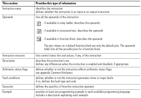
This manual provides a description of each instruction in this format.
The following icons help identify language specific information:
This section Provides this type of informationInstruction name identifies the instruction
defines whether the instruction is an input or an output instruction
Operands lists all the operands of the instruction
Instruction structure lists control status bits and values, if any, of the instruction
Description describes the instruction’s use
defines any differences when the instruction is enabled and disabled, if appropriate
Arithmetic status flags defines whether or not the instruction affects arithmetic status flags see appendix Common Attributes
Fault conditions defines whether or not the instruction generates minor or major faults if so, defines the fault type and code
Execution defines the specifics of how the instruction operates
Example provides at least one programming example in each available programming language includes a description explaining each example
if available in relay ladder, describes the operands
if available in function block, describes the operands
The pins shown on a default function block are only the default pins. The operands table lists all the possible pins for a function block.
if available in structured text, describes the operands
This icon Indicates this programming language relay ladder
structured text
Common Information for
All Instructions
The Logix5000 instruction set has some common attributes:
Conventions and
Related Terms
Set and clear
This manual uses set and clear to define the status of bits (booleans) and
values (non-booleans):
If an operand or parameter supports more than one data type, the bold data
types indicate optimal data types. An instruction executes faster and requires
less memory if all the operands of the instruction use the same optimal data
type, typically DINT or REAL.
Relay ladder rung condition
The controller evaluates ladder instructions based on the rung condition
preceding the instruction (rung-condition-in). Based on the rung-condition-in
and the instruction, the controller sets the rung condition following the
instruction (rung-condition-out), which in turn, affects any subsequent
instruction.
For this information See this appendix
common attributes appendix Common Attributes defines:
arithmetic status flags
data types
keywords
function block attributes appendix Function Block Attributes defines:
program and operator control
timing modes
This term Means
set the bit is set to 1 (ON)
a value is set to any non-zero number
clear the bit is cleared to 0 (OFF)
all the bits in a value are cleared to 0
input instruction
rung-in condition
output instruction
If the rung-in condition to an input instruction is true, the controller evaluates
the instruction and sets the rung-out condition based on the results of the
instruction. If the instruction evaluates to true, the rung-out condition is true;
if the instruction evaluates to false, the rung-out condition is false.
The controller also prescans instructions. Prescan is a special scan of all
routines in the controller. The controller scans all main routines and
subroutines during prescan, but ignores jumps that could skip the execution of
instructions. The controller executes all FOR loops and subroutine calls. If a
subroutine is called more than once, it is executed each time it is called. The
controller uses prescan of relay ladder instructions to reset non-retentive I/O
and internal values.
During prescan, input values are not current and outputs are not written. The
following conditions generate prescan:
Toggle from Program to Run mode
Automatically enter Run mode from a power-up condition.
Prescan does not occur for a program when:
The program becomes scheduled while the controller is running.
The program is unscheduled when the controller enters Run mode.
Function block states
The controller evaluates function block instructions based on the state of
different conditions.
Possible Condition Description
prescan Prescan for function block routines is the same as for relay ladder routines. The only difference is that the EnableIn parameter for each function block instruction is cleared during prescan.
instruction first scan Instruction first scan refers to the first time an instruction is executed after prescan. The controller uses instruction first scan to read current inputs and determine the appropriate state to be in.
Every function block instruction also includes EnableIn and EnableOut
parameters:
function block instructions execute normally when EnableIn is set.
when EnableIn is cleared, the function block instruction either executes
prescan logic, postscan logic, or just skips normal algorithm execution.
EnableOut mirrors EnableIn, however, if function block execution
detects an overflow condition EnableOut is also cleared.
function block execution resumes where it left off when EnableIn
toggles from cleared to set. However there are some function block
instructions that specify special functionality, such as reinitialzation,
when EnableIn toggles from cleared to set. For function block
instructions with time base parameters, whenever the timing mode is
Oversample, the instruction always resumes were it left off when
EnableIn toggles from cleared to set.
If the EnableIn parameter is not wired, the instruction always executes as
normal and EnableIn remains set. If you clear EnableIn, it changes to set the
next time the instruction executes.
Process Control Instructions
(ALM, D2SD, D3SD, DEDT, FGEN, LDLG, PIDE, POSP, RMPS, SCL,
SRTP, TOT)
Introduction
These process control instruction are available in structured text and function
block programming languages:
If you want to Use this instruction Page provide alarming for any analog signal. Alarm (ALM) 24
control discrete devices, such as solenoid valves, pumps, and motors, that have only two possible states such as on/off, open/closed.
Discrete 2-State Device (D2SD)
29
control discrete devices, such as high/low/off feeders, that have three possible states such as fast/slow/off, forward/stop/reverse.
Discrete 3-State Device (D3SD)
38
perform a delay of a single input. You select the amount of deadtime delay.
Deadtime (DEDT) 51
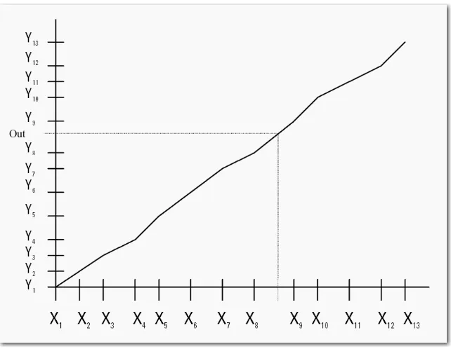
convert an input based on a piece-wise linear function.
Function Generator (FGEN) 56
provide a phase lead-lag compensation for an input signal.
Lead-Lag (LDLG) 60
regulate an analog output to maintain a process variable at a certain setpoint using a PID algorithm.
Enhanced PID (PIDE) 64
raise/lower or open/close a device, such as a motor-operated valve, by pulsing open or close contacts.
Position Proportional (POSP) 100
provide for alternating ramp and soak periods to follow a temperature profile.
Ramp/Soak (RMPS) 107
convert an unscaled input value to a floating point value in engineering units.
Scale (SCL) 121
take the 0-100% output of a PID loop and drive heating and cooling digital output contacts with a periodic pulse.
Split Range Time Proportional (SRTP)
125
provide a time-scaled accumulation of an analog input value, such as a volumetric flow.
Alarm (ALM)
The ALM instruction provides alarming for any analog signal.
Operands:
Structured Text
Function Block
ALARM Structure
Operand Type Format Description
ALM tag ALARM structure ALM structure
Operand Type Format Description
ALM tag ALARM structure ALM structure
ALM(ALM_tag);
Input Parameter Data Type Description
EnableIn BOOL Function Block
If cleared, the instruction does not execute and outputs are not updated. If set, the instruction executes.
Default is set. Structured Text
No effect. The instruction always executes.
In REAL The analog signal input.
Valid = any float Default = 0.0
HHLimit REAL The high-high alarm limit for the input. Valid = any real value
Default = maximumimum positive value
HLimit REAL The high alarm limit for the input. Valid = any real value
Default = maximumimum positive value
LLimit REAL The low alarm limit for the input.
Valid = any real value.
Default = maximumimum negative value
LLLimit REAL The low-low alarm limit for the input. Valid = any real value
Default = maximumimum negative value
Deadband REAL The alarm deadband for the high-high to low-low limits. Valid = any real value 0.0
Description
ROCPosLimit REAL The rate-of-change alarm limit in units per second for a positive (increasing) change in the input. Set ROCPosLimit = 0 to disable ROC positive alarming. If invalid, the instruction assumes a value of 0.0 and sets the appropriate bit in Status.
Valid = any real value 0.0 Default = 0.0
ROCNegLimit REAL The rate-of-change alarm limit in units per second for a negative (decreasing) change in the input. Set ROCPNegLimit = 0 to disable ROC negative alarming. If invalid, the instruction assumes a value of 0.0 and sets the appropriate bit in Status.
Valid = any real value 0.0 Default = 0.0
ROCPeriod REAL The time period used to evaluate the rate-of-change alarms (in seconds). Set ROCPeriod = 0 to disable ROC alarming and set the output ROC to zero. If invalid, the instruction assumes a value of 0.0 and sets the appropriate bit in Status.
Valid = any real value 0.0 Default = 0.0
Input Parameter Data Type Description
Output Parameter Data Type Description
EnableOut BOOL Enable output.
HHAlarm BOOL The high-high alarm indicator.
Default = false
HAlarm BOOL The high alarm indicator.
Default = false
LAlarm BOOL The low alarm indicator.
Default = false
LLAlarm BOOL The low-low alarm indicator.
Default = false
ROCPosAlarm BOOL The rate-of-change positive alarm indicator. Default = false
ROCNegAlarm BOOL The rate-of-change negative alarm indicator. Default = false
ROC REAL The rate-of-change output. Arithmetic status flags are set for this output.
Status DINT Status of the function block.
InstructFault (Status.0) BOOL The instruction detected one of the following execution errors. This is not a minor or major controller error. Check the remaining status bits to determine what occurred.
DeadbandInv (Status.1)
BOOL Invalid Deadband value.
ROCPosLimitInv (Status.2)
BOOL Invalid ROCPosLimit value.
ROCNegLimitInv (Status.3)
BOOL Invalid ROCNegLimit value.
ROCPeriodInv (Status.4)
The ALM instruction provides alarm indicators for high-high, high, low,
low-low, rate-of-change positive, and rate-of-change negative. An alarm
deadband is available for the high-high to low-low alarms. A user defined
period for performing rate-of-change alarming is also available.
High-high to low-low alarm
The high-high and low-low alarm algorithms compare the input to the alarm
limit and the alarm limit plus or minus the deadband.
Rate-of-change alarm
The rate-of-change (ROC) alarm compares the change of the input over the
ROCPeriod to the rate-of-change limits. The ROCPeriod provides a type of
deadband for the rate-of-change alarm. For example, define an ROC alarm
limit of 2
F/second with a period of execution of 100 ms. If you use an
analog input module with a resolution of 1
F, every time the input value
changes, an ROC alarm is generated because the instruction calculates an
effective rate of 10
F/second. However, enter an ROCPeriod of 1 second and
the instruction only generates an alarm if the rate truly exceeds the
2
F/second limit.
The ROC alarm calculates the rate-of-change as:
HHAlarm false
In HHLim
In < (HHLim Deadband)
HHAlarm true
HAlarm false
In HLim
In < (HLim Deadband)
HAlarm true
LLAlarm false
In LLLim
In > (LLLim Deadband)
LLAlarm true
LAlarm false
In LLim
In > (LLim Deadband)
The instruction performs this calculation when the ROCPeriod expires. Once
the instruction calculates the ROC, it determines alarms as:
Monitoring the ALM instruction
There is an operator faceplate available for the ALM instruction. For more
information, see appendix Function Block Faceplate Controls.
Arithmetic Status Flags
Arithmetic status flags are set for the ROC output.
Fault Conditions
none
Execution
ROCPosAlarm false
ROC ROCPosLim
ROC < ROCPosLim
ROCPosAlarm true
ROCPNegAlarm false
ROC ROCNegLim
ROC > ROCNegLim
ROCPNegAlarm true
Condition Function Block Action Structured Text Action
prescan No action taken. No action taken.
instruction first scan All alarm outputs are cleared.
The elapsed time accumulator is cleared.
All alarm outputs are cleared.
The elapsed time accumulator is cleared.
instruction first run All alarm outputs are cleared.
The elapsed time accumulator is cleared.
All alarm outputs are cleared.
The elapsed time accumulator is cleared.
EnableIn is cleared EnableOut is cleared, the instruction does nothing, and the outputs are not updated.
na
EnableIn is set The instruction executes. EnableOut is set.
EnableIn is always set. The instruction executes.
Example
The ALM instruction is typically used either with analog input modules (such
as 1771 I/O modules) that do not support on-board alarming or to generate
alarms on a calculated variable. In this example, an analog input from a
1771-IFE module is first scaled to engineering units using the SCL instruction.
The Out of the SCL instruction is an input to the ALM instruction to
determine whether to set an alarm. The resulting alarm output parameters
could then be used in your program and/or viewed on an operator interface
display.
Structured Text
SCL_01.In := Input0From1771IFE;
SCL(SCL_01);
ALM_01.In := SCL_01.Out;
ALARM(ALM_01);
Discrete 2-State Device
(D2SD)
The D2SD instruction controls a discrete device which has only two possible
states such as on/off, open/closed.
Operands:
Structured Text
Function Block
DISCRETE_2STATE Structure
Operand Type Format Description
D2SD tag DISCRETE_2STATE structure D2SD structure
Operand Type Format Description
D2SD tag DISCRETE_2STATE structure D2SD structure D2SD(D2SD_tag);
Input Parameter Data Type Description
EnableIn BOOL Function Block
If cleared, the instruction does not execute and outputs are not updated. If set, the instruction executes.
Default is set. Structured Text:
No effect. The instruction executes.
ProgCommand BOOL Used to determine CommandStatus when the device is in Program control. When set, the device is commanded to the 1 state; when cleared, the device is commanded to the 0 state. Default is cleared.
Oper0Req BOOL Operator state 0 request. Set by the operator interface to place the device in the 0 state when the device is in Operator control.
Default is cleared.
Oper1Req BOOL Operator state 1 request. Set by the operator interface to place the device in the 1 state when the device is in Operator control.
Default is cleared.
State0Perm BOOL State 0 permissive. Unless in Hand or Override mode, this input must be set for the device to enter the 0 state. This input has no effect for a device already in the 0 state.
State1Perm BOOL State 1 permissive. Unless in the Hand or Override mode, this input must be set for the device to enter the 1 state. This input has no effect for a device already in the 1 state. Default is set.
FB0 BOOL The first feedback input available to the D2SD instruction. Default is cleared.
FB1 BOOL The second feedback input available to the D2SD instruction. Default is cleared.
HandFB BOOL Hand feedback input. This input is from a field hand/off/auto station and it shows the requested state of the field device. When set, the field device is being requested to enter the 1 state; when cleared, the field device is being requested to enter the 0 state.
Default is cleared.
FaultTime REAL Fault time value. Configure the value in seconds of the time to allow the device to reach a newly commanded state. Set FaultTime = 0 to disable the fault timer. If this value is invalid, the instruction assumes a value of zero and sets the appropriate bit in Status.
Valid = any float 0.0 Default = 0.0
FaultAlarmLatch BOOL Fault alarm latch input. When set and FaultAlarm is set, latch FaultAlarm. To unlatch FaultAlarm set FaultAlmUnlatch or clear FaultAlarmLatch.
Default is cleared.
FaultAlmUnLatch BOOL Fault alarm unlatch input. Set FaultAlmUnLatch when FaultAlarmLatch is set to unlatch FaultAlarm. The instruction clears this input.
Default is cleared.
OverrideOnInit BOOL Override on initialization request. If this bit is set, then during instruction first scan, the 2-state device is placed in Operator control, Override is set, and Hand is cleared. If ProgHandReq is set, then Override is cleared and Hand is set.
Default is cleared.
OverrideOnFault BOOL Override on fault request. Set OverrideOnFault if the device should go to Override mode and enter the OverrideState on a fault alarm. After the fault alarm is removed, the 2-state device is placed in Operator control.
Default is cleared.
OutReverse BOOL Reverse default out state. The default state of Out is cleared when commanded to state 0, and set when commanded to state 1. When OutReverse is set, Out is set when commanded to state 0, and cleared when commanded to state 1.
Default is cleared.
OverrideState BOOL Override state input. Configure this value to specify the state of the device when the device is in Override mode. Set indicates that the device should go to the 1 state; cleared indicates that the device should go to the 0 state.
Default is cleared.
FB0State0 BOOL Feedback 0 state 0 input. Configure the state of the FB0 when the device is in the 0 state. Default is cleared.
FB0State1 BOOL Feedback 0 state 1 input. Configure the state of the FB0 when the device is in the 1 state. Default is cleared.
FB1State0 BOOL Feedback 1 state 0 input. Configure the state of the FB1 when the device is in the 0 state. Default is cleared.
FB1State1 BOOL Feedback 1 state 1 input. Configure the state of the FB1 when the device is in the 1 state. Default is cleared.
ProgProgReq BOOL Program program request. Set by the user program to request Program control. Ignored if ProgOperReq is set. Holding this set and ProgOperReq cleared locks the instruction into Program control.
Default is cleared.
ProgOperReq BOOL Program operator request. Set by the user program to request Operator control. Holding this set locks the instruction into Operator control.
Default is cleared.
ProgOverrideReq BOOL Program override request. Set by the user program to request the device to enter Override mode. Ignored if ProgHandReq is set.
Default is cleared.
ProgHandReq BOOL Program hand request. Set by the user program to request the device to enter Hand mode. Default is cleared.
OperProgReq BOOL Operator program request. Set by the operator interface to request Program control. The instruction clears this input.
Default is cleared.
OperOperReq BOOL Operator operator request. Set by the operator interface to request Operator control. The instruction clears this input.
Default is cleared.
ProgValueReset BOOL Reset program control values. When set, all the program request inputs are cleared each execution of the instruction.
Default is cleared. Input Parameter Data Type Description
Output Parameter Data Type Description
EnableOut BOOL Enable output.
Out BOOL The output of the 2-state instruction.
Device0State BOOL Device 0 state output. Set when the device is commanded to the 0 state and the feedbacks indicate the device really is in the 0 state.
Device1State BOOL Device 1 state output. Set when the device is commanded to the 1 state and the feedbacks indicate the device really is in the 1 state.
CommandStatus BOOL Command status output. Set when the device is being commanded to the 1 state and cleared when the device is being commanded to the 0 state.
FaultAlarm BOOL Fault alarm output. Set if the device was commanded to a new state and the FaultTime has expired without the feedbacks indicating that the new state has actually been reached. Also set if, after reaching a commanded state, the feedbacks suddenly indicate that the device is no longer in the commanded state.
ModeAlarm BOOL Mode alarm output. Set if the device is in Operator control and a program command changes to a state which is different from the state currently commanded by the operator. This alarm is intended as a reminder that a device was left in Operator control.
ProgOper BOOL Program/Operator control indicator. Set when in Program control. Cleared when in Operator control.
Override BOOL Override mode. Set when the device is in the Override mode.
Hand BOOL Hand mode. Set when the device is in the Hand mode.
Description
The D2SD instruction controls a discrete device which has only two possible
states such as on/off, open/closed. Typical discrete devices of this nature
include motors, pumps, and solenoid valves.
Monitoring the D2SD instruction
There is an operator faceplate available for the D2SD instruction. For more
information, see appendix Function Block Attributes.
Arithmetic Status Flags
Arithmetic status flags are not affected.
Fault Conditions
none
Execution
InstructFault (Status.0) BOOL The instruction detected one of the following execution errors. This is not a minor or major controller error. Check the remaining status bits to determine what occurred.
FaultTimeInv (Status.1) BOOL Invalid FaultTime value. The instruction sets FaultTime = 0.
OperReqInv (Status.2) BOOL Both operator state request bits are set. Output Parameter Data Type Description
Condition Function Block Action Structured Text Action
prescan No action taken. No action taken.
instruction first scan The fault timer is cleared. ModeAlarm is cleared.
All the operator request inputs are cleared.
If ProgValueReset is set, all the program request inputs are cleared. When OverrideOnInit is set, ProgOper is cleared (Operator control).
If ProgHandReq is cleared and OverrideOnInit is set, clear Hand and set Override (Override mode). If ProgHandReq is set, set Hand and clear Override (Hand mode).
instruction first run ProgOper and CommandStatus are cleared. ProgOper and CommandStatus are cleared.
EnableIn is cleared EnableOut is cleared, the instruction does nothing, and the outputs are not updated.
na
EnableIn is set The instruction executes. EnableOut is set.
EnableIn is always set. The instruction executes.
Example
The D2SD instruction is typically used to control on-off or open-close devices
such as pumps or solenoid valves. In this example, the D2SD instruction
controls a solenoid valve adding corn syrup to a batch tank. As long as the
D2SD instruction is in Program control, the valve opens when the AddSyrup
input is set. The operator can also take Operator control of the valve to open
or close it if necessary. The solenoid valve in this example has limit switches
that indicate when the valve is fully closed or opened. These switches are wired
into the FB0 and FB1 feedback inputs. This allows the D2SD instruction to
generate a FaultAlarm if the solenoid valve does not reach the commanded
state within the configured FaultTime.
Structured Text
SyrupController.ProgCommand := AddSyrup;
SyrupController.FB0 := SyrupValveClosedLimitSwitch;
SyrupController.FB1 := SyrupValveOpenedLimitSwitch;
D2SD(SyrupController);
SyrupValve := SyrupController.Out;
Switching between Program control and Operator control
The following diagram shows how the D2SD instruction changes between
Program control and Operator control.
(1) The instruction remains in Operator control mode when ProgOperReq is set.
For more information on program and operator control, see page 381.
Commanded state in Program control
The following diagram illustrates how the D2SD instruction operates when in
Program control.
Program Control Operator Control
OperOperReq is set when ProgProgReq is cleared
ProgOperReq is set (1)
Override transitions from set to cleared and Hand is cleared
Hand transitions from set to cleared and Override is cleared
ProgProgReq is set when ProgOperReq is cleared
OperProgReq is set when ProgOperReq is cleared and OperOperReq is cleared
Set Command Status Clear Command Status
ProgCommand is cleared State0Perm is set
Commanded state in Operator control
The following diagram illustrates how the D2SD instruction operates when in
Operator control.
If both Oper0Req and Oper1Req are set:
the instruction sets the appropriate bit in Status
if Override and Hand are cleared, the instruction holds the
previous state.
After every instruction execution, the instruction:
clears all the operator request inputs
if ProgValueReset is set, clears all the program request inputs
Hand mode or Override mode
The following table describes how the D2SD instruction determines whether
to operate in Hand or Override mode
When the instruction is in Override mode, CommandStatus = OverrideState
When the instruction is in Hand mode, CommandStatus = HandFB
Set Command Status Cleared Command Status
Oper0Req is set State0Perm is set
Oper1Req is set State1Perm is set
ProgHandReq ProgOverrideReq FaultAlarm and OverrideOnFault
Description
set either either Hand mode
Hand is set Override is cleared
cleared set either Override mode
Hand is cleared Override is set
cleared either set Override mode
Output state
The D2SD output state is based on the state of the command status.
Fault alarm conditions
The D2SD instruction checks for these fault alarm conditions.
FaultAlarm is cleared if one of the following conditions is met:
CommandStatus is cleared and Device0State is set
CommandStatus is set and Device1State is set
FaultTime
0
FaultAlarm cannot be cleared when FaultAlarmLatch is set, unless
FaultAlmUnlatch is set and no fault is present.
CommandStatus Output state
cleared if OutReverse is cleared, Out is cleared if OutReverse is set, Out is set
set if OutReverse is cleared, Out is set
if OutReverse is set, Out is cleared
cleared and FB0 = FB0State0 and FB1 = FB1State0
the fault timer is stopped and cleared Device0State is set
set and
FB0 = FB0State1 and FB1 = FB1State1
the fault timer is stopped and cleared Device1State is set
Fault alarm condition resulting from Rules device state was commanded to change,
but the feedback did not indicate that the desired state was actually reached within the FaultTime.
Start the fault timer when:
CommandStatusn CommandStatusn-1
Set FaultAlarm when:
fault timer is done and FaultTime > 0.0
the device unexpectedly leaving a state (according to the feedback) without being commanded to.
Set FaultAlarm when:
fault timer is not timing and one of the following conditions is satisfied:
• CommandStatus is cleared and Device0State is cleared
Mode alarm conditions
The mode alarm reminds an operator that a device has been left in operator
control. The mode alarm only turns on when in operator control mode, the
program tries to change the state of the device from the operator’s
commanded state. The alarm does not turn on if an operator places a device in
operator mode and changes the state. The D2SD instruction checks for mode
alarm conditions, using these rules.
ModeAlarm: When:
set ProgCommandn ProgCommandn-1and
ProgCommandnCommandStatus
cleared ProgCommand = CommandStatus or
Discrete 3-State Device
(D3SD)
The D3SD instruction controls a discrete device having three possible states
such as fast/slow/off, forward/stop/reverse.
Operands:
Structured Text
Function Block
DISCRETE_3STATE Structure
Operand Type Format Description
D3SD tag DISCRETE_3STATE structure D3SD structure
Operand Type Format Description
D3SD tag DISCRETE_3STATE structure D2SD structure D3SD(D3SD_tag);
Input Parameter Data Type Description
EnableIn BOOL Function Block
If cleared, the instruction does not execute and outputs are not updated. If set, the instruction executes.
Default is set. Structured Text:
No effect. The instruction executes.
Prog0Command BOOL Program state 0 command. This input determines the device state when the device is in Program control. If set, the device is commanded to the 0 state.
Default is cleared.
Prog1Command BOOL Program state 1 command. This input determines the device state when the device is in Program control. If set, the device is commanded to the 1 state.
Default is cleared.
Oper0Req BOOL Operator state 0 request. Set by the operator interface to place the device into the 0 state when the device is in Operator control.
Default is cleared.
Oper1Req BOOL Operator state 1 request. Set by the operator interface to place the device into the 1 state when the device is in Operator control.
Default is cleared.
Oper2Req BOOL Operator state 2 request. Set by the operator interface to place the device into the 2 state when the device is in Operator control.
Default is cleared.
State0Perm BOOL State 0 permissive. Unless in Hand or Override mode, this input must be set for the device to enter the 0 state. This input has no effect if the device is already in the 0 state.
Default is set.
State1Perm BOOL State 1 permissive. Unless in Hand or Override mode, this input must be set for the device to enter the 1 state. This input has no effect if the device is already in the 1 state.
Default is set.
State2Perm BOOL State 2 permissive. Unless in Hand or Override mode, this input must be set for the device to enter the 2 state. This input has no effect if the device is already in the 2 state.
Default is set.
FB0 BOOL The first feedback input available to the instruction. Default is cleared.
FB1 BOOL The second feedback input available to the instruction. Default is cleared.
FB2 BOOL The third feedback input available to the instruction. Default is cleared.
FB3 BOOL The fourth feedback input available to the instruction. Default is cleared.
HandFB0 BOOL Hand feedback state 0. This input from a field hand/off/auto station shows the requested state of the field device. Set indicates that the field device is being requested to enter the 0 state; cleared indicates that the field device is being requested to enter some other state. Default is cleared.
HandFB1 BOOL Hand feedback state 1. This input from a field hand/off/auto station shows the requested state of the field device. Set indicates that the field device is being requested to enter the 1 state; cleared indicates that the field device is being requested to enter some other state. Default is cleared.
HandFB2 BOOL Hand feedback state 2. This input from a field hand/off/auto station shows the requested state of the field device. Set indicates that the field device is being requested to enter the 2 state; cleared indicates that the field device is being requested to enter some other state. Default is cleared.
FaultTime REAL Fault time value. Configure the value in seconds of the time to allow the device to reach a newly commanded state. Set FaultTime = 0 to disable the fault timer. If this value is invalid, the instruction assumes a value of zero and sets the appropriate bit in Status.
Valid = any float 0.0 Default = 0.0
FaultAlarmLatch BOOL Fault alarm latch input. When set and FaultAlarm is set, latch FaultAlarm. To unlatch FaultAlarm, set FaultAlmUnlatch or clear FaultAlarmLatch.
FaultAlmUnLatch BOOL Fault alarm unlatch input. Set this input when FaultAlarmLatch is set to unlatch FaultAlarm. The instruction clears this input.
Default is cleared.
OverrideOnInit BOOL Override on initialization request. If this bit is set, then during instruction first scan, the instruction is placed in Operator control with Override set and Hand cleared. If ProgHandReq is set, then Override is cleared and Hand is set.
Default is cleared.
OverrideOnFault BOOL Override on fault request. Set this value if the device should go to Override mode and enter the OverrideState on a fault alarm. After the fault alarm is removed, the instruction is placed in Operator control.
Default is cleared.
Out0State0 BOOL Output 0 state 0 input. This value determines the value of Output0 when the device is in the 0 state.
Default is cleared.
Out0State1 BOOL Output 0 state 1 input. This value determines the value of Output0 when the device is in the 1 state.
Default is cleared.
Out0State2 BOOL Output 0 state 2 input. This value determines the value of Output0 when the device is in the 2 state.
Default is cleared.
Out1State0 BOOL Output 1 state 0 input. This value determines the value of Output1 when the device is in the 0 state.
Default is cleared.
Out1State1 BOOL Output 1 state 1 input. This value determines the value of Output1 when the device is in the 1 state.
Default is cleared.
Out1State2 BOOL Output 1 state 2 input. This value determines the value of Output1 when the device is in the 2 state.
Default is cleared.
Out2State0 BOOL Output 2 state 0 input. This value determines the value of Output2 when the device is in the 0 state.
Default is cleared.
Out2State1 BOOL Output 2 state 1 input. This value determines the value of Output2 when the device is in the 1 state.
Default is cleared.
Out2State2 BOOL Output 2 state 2 input. This value determines the value of Output2 when the device is in the 2 state.
Default is cleared.
OverrideState DINT Override state input. Set this input to indicate the state of the device when in Override mode. Value: Indicates:
2 device should go to the 2 state 1 device should go to the 1 state 0 device should go to the 0 state
An invalid value sets the appropriate bit in Status and prevents the instruction from entering the override state.
FB0State0 BOOL Feedback 0 state 0 input. This value determines the expected value of FB0 when the device is in the 0 state.
Default is cleared.
FB0State1 BOOL Feedback 0 state 1 input. This value determines the expected value of FB0 when the device is in the 1 state.
Default is cleared.
FB0State2 BOOL Feedback 0 state 2 input. This value determines the expected value of FB0 when the device is in the 2 state.
Default is cleared.
FB1State0 BOOL Feedback 1 state 0 input. This value determines the expected value of FB1 when the device is in the 0 state.
Default is cleared.
FB1State1 BOOL Feedback 1 state 1 input. This value determines the expected value of FB1 when the device is in the 1 state.
Default is cleared.
FB1State2 BOOL Feedback 1 state 2 input. This value determines the expected value of FB1 when the device is in the 2 state.
Default is cleared.
FB2State0 BOOL Feedback 2 state 0 input. This value determines the expected value of FB2 when the device is in the 0 state.
Default is cleared.
FB2State1 BOOL Feedback 2 state 1 input. This value determines the expected value of FB2 when the device is in the 1 state.
Default is cleared.
FB2State2 BOOL Feedback 2 state 2 input. This value determines the expected value of FB2 when the device is in the 2 state.
Default is cleared.
FB3State0 BOOL Feedback 3 state 0 input. This value determines the expected value of FB3 when the device is in the 0 state.
Default is cleared.
FB3State1 BOOL Feedback 3 state 1 input. This value determines the expected value of FB3 when the device is in the 1 state.
Default is cleared.
FB3State2 BOOL Feedback 3 state 2 input. This value determines the expected value of FB3 when the device is in the 2 state.
Default is cleared.
ProgProgReq BOOL Program program request. Set by the user program to request Program control. Ignored if ProgOperReq is set. Holding this set and ProgOperReq cleared locks the instruction in Program control.
Default is cleared.
ProgOperReq BOOL Program operator request. Set by the user program to request operator control. Holding this set locks the instruction in Operator control.
Default is cleared.
ProgOverrideReq BOOL Program override request. Set by the user program to request the device to enter Override mode. Ignored if ProgHandReq is set.
Default is cleared.
ProgHandReq BOOL Program hand request. Set by the user program to request the device to enter Hand mode. Default is cleared.
OperProgReq BOOL Operator program request. Set by the operator interface to request Program control. The instruction clears this input.
Default is cleared.
OperOperReq BOOL Operator operator request. Set by the operator interface to request Operator control. The instruction clears this input.
Default is cleared.
ProgValueReset BOOL Reset program control values. When set, all the program request inputs are cleared each execution of the instruction.
Default is cleared. Input Parameter Data Type Description
Output Parameter Data Type Description
EnableOut BOOL Enable output.
Out0 BOOL The first output of the instruction.
Out1 BOOL The second output of the instruction.
Out2 BOOL The third output of the instruction.
Device0State BOOL Device 0 state output. Set when the device is commanded to the 0 state and the feedback indicates the device really is in the 0 state.
Device1State BOOL Device 1 state output. Set when the device is commanded to the 1 state and the feedback indicates the device really is in the 1 state.
Device2State BOOL Device 2 state output. Set when the device is commanded to the 2 state and the feedback indicates the device really is in the 2 state.
Command0Status BOOL Device 0 command status. Set when the device is being commanded to the 0 state; cleared when the device is being commanded to some other state.
Command1Status BOOL Device 1 command status. Set when the device is being commanded to the 1 state; cleared when the device is being commanded to some other state.
Command2Status BOOL Device 2 command status. Set when the device is being commanded to the 2 state; cleared when the device is being commanded to some other state.
FaultAlarm BOOL Fault alarm output. Set if the device has been commanded to a new state, and the FaultTime has expired without the feedback indicating that the new state has actually been reached. Also set if, after reaching a commanded state, the feedbacks suddenly indicate that the device is no longer in the commanded state.
ModeAlarm BOOL Mode alarm output. Set if the device is in operator control and a program command changes to a state which is different from the state currently commanded by the operator. This alarm is intended as a reminder that a device was left in Operator control.
ProgOper BOOL Program/operator control indicator. Set when in Program control. Cleared when in Oper