NEW MODEL OF A SOLAR WIND AIRPLANE FOR GEOMATIC OPERATIONS
A. Achachi a, *, D. Benatia b
a
Dept of Electronic, University Lhaj lakhdar Batna, Algeria - [email protected] b Dept of Electronic, University Lhaj lakhdar Batna, Algeria - Dj-benatia @yahoo.fr
Commission VI, WG VI/4
KEY WORDS: Geomatic,Telecommunication, Autopilot, Electrical power, Renewable energy
ABSTRACT:
The ability for an aircraft to fly during a much extended period of time has become a key issue and a target of research, both in the domain of civilian aviation and unmanned aerial vehicles. This paper describes a new design and evaluating of solar wind aircraft with the objective to assess the impact of a new system design on overall flight crew performance. The required endurance is in the range of some hours in the case of law enforcement, border surveillance, forest fire fighting or power line inspection. However, other applications at high altitudes, such as geomatic operations for delivering geographic information, weather research and forecast, environmental monitoring, would require remaining airborne during days, weeks or even months. The design of GNSS non precision approach procedure for different airports is based on geomatic data.
* Corresponding author
1. INTRODUCTION
The use of the renewable energy in aviation is growing step by
step. For the moment, it is only possible to reach such ambitious goals using electric solar powered platforms (Alves, J., Dube, L. and Ohnstad, C., 2006). Photovoltaic modules (Miles, R. W., Hynes, K. M. and Forbes, I., 2005) may be used to collect the energy of the sun during the day, one part being used directly to power the propulsion unit and onboard instruments (Noth, A., Engel, W. and Siegwart, R., 2005b), the other part being stored for the night time.
In order to reach the target endurance, the design of the aeroplane has to be thought carefully, as a system composed of many subsystems that are continuously exchanging energy (Engel, C. J., Woodworth, A. J. and Drela, M., 2007). Due to these relationships, each part has to be sized accordingly to all the others. Simply because of a crucial part lies in the combination of all the elements, and not only in their quality. This is especially true for multidisciplinary projects, the case of a solar wind aeroplane being an ideal example as it requires knowledge in the fields of aerodynamics (Wilson, C., Nutbean, J. and Bond, I., 2000), actuators, sensors, electronics, energy storage, photovoltaic, etc.
Geomatic is the operation of gathering, storing, processing, and delivering geographic information, it consists of products, services and tools involved in the collection, integration and management of geographic data. These operations can be used in order to perform GNSS non precision approach procedure for different airports.
The autopilot system is essential in solar wind aircraft. Autopilot system improves the accuracy and reliability in flying
operation, reduces the pilots’ workload to some degrees. At the same time, automation also brings a change in cockpit interface design (Chengqi, X., Cen, Q. Yan, Z., 2009), operating method and work procedure. This article is to design a sort of reliable machine in the air which can improve collecting geomatic data.
This paper is organized as follows: Section II presents the data model and lists the assumptions and some preliminary notions. Section III presents the design of the solar wind airplane and the cockpit and Section IV is reserved to the discussion and Section V will be the conclusion.
2. DATA MODEL AND PRELIMINARY
In order to locate clearly where the contributions lie, we should first recall that the design process of a solar aeroplane is composed of three main phases (Raymer, D. P., 1999):
Conceptual Design: it is in this phase that the basic questions of configurations arrangement, size, weight and performance are answered. The design requirements are used to guide and evaluate the development of the overall aircraft configuration.
Preliminary Design: during this phase, the specialists in areas such as structures, control systems, propulsion, etc. will design and analyze their portion of the aircraft. The design evolves with ever-increasing level of understanding and confidence that it will work.
Detail Design: the detail design phase begins in which the actual pieces to be fabricated are designed. The many little pieces not considered during the two first
phases must be designed such as instrument and the whole cockpit interface design.
Figure.1 Solar aeroplane basic principle
The solar panels, composed by solar cells connected in a defined configuration, cover a given surface of the wing or potentially other parts of the aeroplane like the tail or the fuselage. During the day, depending on the sun irradiance and elevation in the sky, they convert light into electrical energy. A converter ensures that the solar panels are working at their maximum power point. That is the reason why this device is called a Maximum Power Point Tracker MPPT (Noth, A., 2006a). This power obtained is used firstly to supply the
propulsion group and the onboard electronics “Fig. 1”, and to
charge the battery with the surplus of energy.
During the night, as no more power comes from the solar panels, the various elements consuming energy are supplied by the battery that has to last until the next morning where a new cycle starts; in addition we add two small propellers mounted on back wing which produces just enough energy to feed the electricity. They gain the energy from the plane gliding along. These small wind power propeller generators generate power from the wind so that they can create electricity (Ewind) and contribute to the recharging the batteries at night or cloudy day. However during climbing phase these propellers are set on feathered position to avoid air drag force.
2.1 Aerodynamics of Wings
The circulation of this airflow creates a different pressure distribution on the upper and lower side of the wings that once integrated can be represented as two forces, the lift and the drag which can be calculated using the following equations:
2
Where CL and CD are respectively the lift and drag coefficients, ρ is the air density, S the wings surface and V the relative airspeed.
2.2 Solar Cell
A solar cell or photovoltaic cell (Miles, R. W., Hynes, K. M. and Forbes, I., 2005) is a device that converts solar energy into electricity by the photovoltaic effect. It is very widely used in
Day
Night Solar Panels
Motor, Electronics.. The International Archives of the Photogrammetry, Remote Sensing and Spatial Information Sciences, Volume XL-1/W4, 2015
space application (Diepeveen, N., 2007) because it allows a clean and long-duration source of energy requiring almost no maintenance. Solar cells are composed of various semiconducting materials, constituting one or more layers. Silicon is very often used as it is the second most abundant
element in Earth‘s crust and thus inexpensive. Solar cells mono crystalline silicon, 130 micron thickness.
2.3 Wind Energy
The technology of wind turbine is used in this model to generate a part of electrical power. The speed of aircraft and the rotation
of engines’ propellers push the air towards generator propellers
which provide some electrical power.
2.4 Human Computer Interaction
In modern control systems (Degani, A., Shafto, M. and Kirlik, A), a mode is a common architecture for grouping several devices (instruments) configurations under one label. The set of modes in a control system corresponds to a set of unique machine behaviors. The pilot interacts with the instruments by switching among modes manually, or monitoring the automatic switching triggered by the instruments.An important element in the assessment of user expectations is the user ability to sense the conditions that trigger a transition. Specifically, the pilot must be able to sense the events (e.g Flight Director is engaged; aircraft is more than 2000 feet above the ground) and then evaluate whether or not the transition to a mode (e.g Vertical Navigation) will take place. These events are usually made known to the pilot through a perfect interface.
In the Human Computer Interaction (HCI) literature, most authors consider modes a method for changing the format of the
interface. The user’s input to the computer is interpreted
differently according to the active mode for example, the Mode Control Panel (MCP) of a Boeing B-737 is the interface through which the pilots interact with the Automatic Flight Control System of the aircraft. The automatic Vertical Navigation (VNAV) mode is active, the speed parameter is obtained from the Flight Management Computer (FMS), which computes the most economical speed for the particular flight regime. Yet another option, called Speed Intervene, allows the pilot to override the Flight Management Computer input and manually enter a different speed by pressing the speed knob and then dialing in the desired speed to the Mode Control Panel and the proposed solar aircraft must be equipped by such interface.
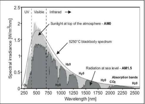
2.5 Working Principles
A simple silicon solar cell is used. When the sunlight strikes the solar cell surface the cell creates charge carriers as electrons and holes. The internal field produced by junction separates some of the positive charges from the negative charges. The holes are swept into the positive or player and the electrons are swept into the negative or n-layer. When a circuit is made, the free reference solar spectral irradiance AM0 (Air Mass 0) represents the irradiance at the top of the atmosphere with a total energy of 1353W/m2. At sea level, it is referred as AM1.5 and the total energy equals 1000W/m2.
3. SOLAR WIND AIRCRAFT DESIGN
The methodology is based on three simple balances, which are:
Weight balance: the lift force has to be equal to the weight of all the elements constituting the airplane.
Energy balance: we will first establish the expression of the power needed for an aircraft at flight level and then present the irradiance model that will lead to the daily solar energy available.
Integrated cockpit architecture : the display of information must be in the form of glass cockpits which reflects the improved understanding of the human cognitive process.
3.1 Daily Electrical Energy Required
At steady level flight, the lift force generated by the wings exactly compensates for the weight and the propeller thrust compensates for the drag force. Using (1) and (2) we can write:
2
To obtain the total electrical power consumption Pelec tot, efficiencies of the motor, its electronic controller, the gearbox and the propeller have to be taken into account, as well as the power consumption of the avionic system Pav and the payload instruments Ppld.If the voltage of these two last elements has to be reduced, the efficiency of the step-down has to be
The calculation of this daily energy consumption uses the total power consumption (7) and takes into account the charge and discharge efficiency of the battery (Dorrington, G. E., 2007) for the night period.
It is clear that both sources, the solar generator and the battery are used and that the switch from one source to the other is progressive.
3.2 Daily Solar Energy Obtained
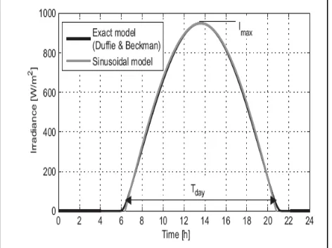
The irradiance depends on a lot of variables such as geographic location, time, plane orientation and weather conditions. A good model was developed based on (Goraj, Z. X., Frydrychiewicz, A. and Winiecki, J) For the present need, this model was simplified for flat surfaces and replaced with the positive part of a sinusoid, as shown in “Fig. 3”.
Here we will use a simple trigonometric model with only two parameters, the maximum irradiance Imaxand the duration of the day Tday,that can be easily interpreted. The daily solar energy per square meter is the surface below the curve and can be easily calculated in (9). In order to take into account cloudy days, a constant ηwther is added with a value between 1 (clear sky) and 0 (dark). This constitutes a margin for the calculation.
Figure 3. Approximation of irradiance as a sinusoid
configuration and preferably dispose the cells connected in series along the wings, so that they have the same orientation, thus, the daily electrical energy is:
wind
This approach consists in calculating separately the mass of all the elements constituting the airframe, i.e. the spar, the leading and trailing edges, covering, ribs, control surfaces, fuselage and tail as functions of the total mass, aspect ratio and wing area with a weight between 1000 to 1600 kg with 21.4 m wingspan.
Concerning the battery (Dorrington, G. E., 2007), its mass is directly proportional to the energy it needs to store, which is the product between power consumption and night duration, and inversely proportional to its gravimetric energy density. Example of this is the lithium ion polymer battery.
They are lightweight, flexible and have the ability to store more energy. Batteries with these features are essential piece for the solar aircraft. Because each battery has 70 accumulators for a total of 280 accumulators. And they can store 200Wh/kg.
(control electronics, motor, gearbox and propeller) that all have their own power densities and efficiencies. Additionally, we will always consider the maximum continuous power and not the short time peak power.Looking at the past solar airplane designs (Goraj, Z. X., Frydrychiewicz, A. and Winiecki, J), the main tendency is to assume a propulsion group mass that scales linearly with shaft power output. Also, many of them only take the motor into account, stating that it constitutes the major weight compared to the other parts.
Materials and structure are essentially constructed from carbon fiber and sandwich structure is used with very thin materials with the lowest possible densities.
3.3 New Integrated Cockpit Architecture
Current cockpits are the result of the evolution of the glass cockpit in a bottom up manner. New pieces of automation are added which often bring their own sets of interfaces, displays and methods of interaction. We assume that pilots have mental models of how to interact with cockpit systems (Lüdtke, A., Osterloh, J. P. Frische, F), like the FMS. The mental model of flight procedures is initially formed based on normative activities acquired through handbooks and in simulator training sessions. Then during repetitive performance the mental model is modified by routine learning processes like Learned The International Archives of the Photogrammetry, Remote Sensing and Spatial Information Sciences, Volume XL-1/W4, 2015
Carelessness. The theory states that humans have a tendency to neglect safety precautions if this has immediate advantages, e.g. it saves time because less physical or cognitive resources are necessary. Careless behaviour emerges if safety precautions have been followed several times but would not have been necessary, because no hazards occurred. Then, people tend to omit the safetyThe purpose and often the basics of the design of the new equipment are normally known well in advance. It would therefore seem sensible to develop a top down integrated cockpit architecture that would provide a more structured, coherent basis for the solar aircraft cockpits. The new architecture would provide better support to the pilots in the task of flying the aircraft.
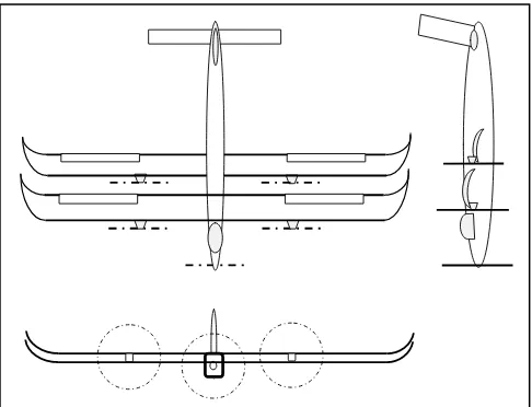
Wingspan (two wings) 21.4 m
Length 9.8 m
Height 4.4 m
Weight 1260 kg
Motor power 3 x 10HP electric engines
Average flying speed 82 km/h
Motors number 3
TABLE I. TECHNICAL DATASHEET OF SOLAR AIRPLANE
Figure 4. Drawings of the Solar Airplane prototype
4. DISCUSSION AND FACED CHALLENGES
The electric energy supplied by wind turbine is participating in the motor supply and delays unloading of batteries. Current models with only batteries require little more batteries to ensure sufficient autonomy during the night and this lead us to have heavy aircraft. However, in our model, using wind energy, batteries are largely sufficient to supply engines during the whole night and even during cloudy day then a new cycle begins in the morning with the solar energy. Fig. 5 represents the unloading of batteries for our model and existing models.
Figure 5. Unloading batteries for our model and existing ones
4.1 Geomatic for aircraft approach procedure
To satisfy demanding phases of flight such as approaches and terminals with vertical guidance could be targeted using GNSS to provide integrity monitoring. To deal with this, we have to make calculations and field layouts of horizontal, vertical and spiral curves when conducting detailed surveys on natural ground such as mountains, hills and plains following the coming steps:
Prepare detailed drawings, charts, plans, reports, and survey altitudes and distance from given point.
Extract surveying and specific user-defined information from remotely sensed images.
Use receivers to monitor earth orbiting satellites to determine geographic positions
These operations have to be made carefully and using high technology equipment in order to get perfect results.
4.2Challenges
However, the using of this aircraft imposes several technical challenges:
Meteorological conditions : this aircraft must fly at flight level 600 (60000 feet) in order to escape from bad weather and other traffic.
The goal of this aircraft is to cover a given area
which is defined as a circular zone in order to acquire all geographical information on ground by receiving pictures.
The aircraft must be equipped with a large L-band
active and UHF/VHF communication tools.
4.3Using Space-Based Automatic Dependent Surveillance Broadcast (ADS-B)
Automatic Dependent Surveillance Broadcast (Helmut, B. and Patrick, R., 2012) is a technology that enables Air Traffic Management (ATM) services using aircraft broadcasting signals including flight data information on a regular basis during all phases of flight on a regular basis. The signal includes flight related information such as speed, altitude, and position; enabling air-to-air and air-to-ground surveillance.
0 2 4 6 8 10 12 14 0
10 20 30 40 50 60 70 80 90 100
Time(Hour)
%
o
f
E
le
c
tr
ic
c
h
a
rg
in
g
Battery supply wind energy Battery
ADS-B is principaly a terrestrial based system which are currently deployed as an add-on to radars or as an alternative in regions were a traditional ATM system based on radar stations is not ensured.
CONCLUSION
As it has been shown in previous sessions, the proposed solar wind airplane can be used to ensure different missions, especially geomatic operations to get more information about
ground. The development of this aircraft, with small wingspan
comparing to ancient model, will allow a high degree of liberty in different operations and improve the world economics and decrease the rate of pollution of the air.
This aircraft can ensure multiple tasks such as aerial photo, and
provide services and tools involved in the collection, integration and management of geographic data with no use of traditional energy and it is considered as independent system for each country.
ACKNOWLEDGEMENTS
The author wishes to thank the department of aerodynamics and microwave of university of Batna for the help provided.
REFERENCES
Alves, J., Dube, L. and Ohnstad, C., 2006. Solar Powered UAV Prototype Log and Results. MEG 498 Final Written Reports. University of Nevada, Las Vegas, Howard R. Hughes College of Engineering.
Chengqi, X., Cen, Q. Yan, Z., 2009. Design and research of human-computer interaction interface in autopilot system of aircraft. 978-1-4244-5268-2/09 IEEE, pp. 1498-1501.
Degani, A., Shafto, M. and Kirlik, A., Modes in Human-Machine Systems Review, Classification, and Application. International Journal of Aviation Psychology, (9), pp.125-138.
Diepeveen, N., 2007. The Sun-Surfer: Design and Construction of a Solar Powered MAV. Bachelor Thesis, Autonomous Systems Lab, ETH Zürich, Switzerland.
Dorrington, G. E., 2007. Performance of Battery-Powered Airships. Proc. Of the IMechE Part G Journal of Aerospace Engineering, (14), pp. 91–104.
Engel, C. J., Woodworth, A. J. and Drela, M., 2007. Design and Testing of a Solar Powered High Endurance UAV. Massachusetts Institute of Technology, Cambridge, MA, 02139.
Goraj, Z. X., Frydrychiewicz, A. and Winiecki, J., 1999. Design Concept of a High-Altitude Long-Endurance Unmanned Aerial Vehicle. Aircraft Design, (2), pp. 19–44.
Helmut, B. and Patrick, R., 2012. Space-Based Automatic Dependent Surveillance Broadcast (ADS-B) Payload for In-Orbit Demonstration. 6th advanced satellite multimidia systems conference and signal processing for space communication.
Lüdtke, A., Osterloh, J. P. Frische, F., Multi-Criteria Evaluation of Aircraft Cockpit Systems by Model-based Simulation of Pilot Performance. OFFIS Institute for Information Technology, Escherweg 2, 26121 Oldenburg.
Miles, R. W., Hynes, K. M. and Forbes, I., 2005. Photovoltaic Solar Cells. An Overview of State-of-the-Art Cell Development and Environmental Issues. Progress in Crystal Growth and Characterization of Materials, (51), pp.1–42.
Noth, A., 2006a, Design of a Lightweight & High Efficiency MPPT for Sky-Sailor Airplane. Internal Technical Report, Autonomous Systems Lab, ETH Zürich, Switzerland.
Noth, A., Engel, W. and Siegwart, R., 2005b. Design of an Ultra-Lightweight Autonomous Solar Airplane for Continuous Flight. In Proc. of the Field and Service Robotics Conference, Port Douglas, Australia.
Raymer, D. P., 1999. Aircraft Design: a Conceptual Approach. AIAA Education Series. American Institute of Aeronautics and Astronautics, Washington, D.C, 3rd edition.
Wilson, C., Nutbean, J. and Bond, I., 2000. Aerodynamic and Structural Design of a Solar-Powered Micro Unmanned Air Vehicle. Proc. of the IMechE, Part G: Journal of Aerospace Engineering, (10), pp. 97–106.