The Effect of Loading on the Contact Stress of UHMWPE
Material for Artificial Hip Joint Bearing
Eko Saputraa, Rifky Ismaila, Jamaria and Iwan Budiwan Anwarb
a
Laboratory for Engineering Design and Tribology, Department of Mechanical Engineering, University of Diponegoro Jl. Prof Sudharto, SH - Tembalang, Semarang INDONESIA
b
Orthopaedic Hospital dr. Soeharso, Solo,
Jl. Jend. Ahmad Yani, pabelan, Surakarta INDONESIA E-mail : [email protected]
Abstract :
An artificial hip joint consists of several main components. The components are femoral stem, femoral head, acetabular liner and acetabular shell. As its function as a bearing, an acetabular liner is designed to reduce friction and receive the high stress. The liner is made from Ultra High Molecular Weight Polyethylene (UHMWPE) material. It is reported that the UHMWPE liner bearing is occasionally fails inside the patie t’s od . This pape epo ts the effe t of loadi g o the li e a d p edi ts the li e a ilit i e ei i g the load. A finite element simulation is employed in modeling the contact system. The maximum load received by the artificial hip joint during human activities is used as input in the artificial hip joint models. The result shows that the acetabular liner receives the high stress distribution and the highest stress is located on the center of the liner. The maximum stress on the acetabular liner does not exceed the yield criteria of the UHMWPE material. It is concluded that the UHMWPE material is relatively able to carry the various loading. However, the failure of the acetabular liner can be caused by the unexpected conditions when the patient stumbles or falls down.
Keywords: artificial hip joint, contact stress , finite element analysis , UHMWPE
1. Introduction
An artificial hip joint consists of several main components. The components are femoral stem, femoral head, acetabular liner and acetabular shell. The acetabular liner is located between femoral head and acetabular shell. As its function as a bearing, an acetabular liner is designed to reduce friction and receive high contact stress. An acetabular liner is made from Ultra High Molecular Weight Polyethylene (UHMWPE) material. Unfortunately, it is
epo ted that the UHMWPE li e ea i g o asio all fails i side the patie t’s body, as shown in Figure 1 [1]. Due to this condition, it is necessary to investigate the causes. The study on the interacting bodies/surfaces, such as contact and interaction between femoral head and acetabular liner is a part of the Tribology science. Tribology is the science and technology of interacting surfaces in relative motion, and includes the study of friction, wear and lubrication.
The study of artificial hip joints began in 1938. The material of the artificial hip joint was made from steel. Previously, an artificial hip joints using metal-on-metal material is predicted to reach 20 years [4] of its lifespan. The term of metal-on-metal means, the material of the femoral head and the liner bearing is made from metal. However, this artificial hip joint failed within 2 to 4 years. The failure is caused by the lack of fixation and the extreme wear.
Due to this condition, McKee and his coworkers [5] and Watson-Farrar [6] conducted more research on the artificial hip joint in the 1960s. The material of the artificial hip joints (head and acetabular liner) are cobalt-chrome-molybdenum. This type still used metal-on-metal with different material selection. This model showed an improvement but this model can only last for 2 to 10 years. The failure is caused by the unsuitable design
Until now, the artificial hip joint, which widely used, is metal-on-polyethylene. This model is able to reduce wear and friction significantly. The data from the Orthopaedic hospital (RSO) dr. Soeharso Solo shows that the metal-on-polyethylene is the main material for the artificial hip joint in this hospital. Considering the failure of the acetabular liner, which is made polyethylene (UHMWPE), some investigations is conducted to study the causes. This paper studies the contact simulation of artificial hip joints using UHMWPE as an acetabular liner. The objective of this research is investigating the effect of loading during human activities on the contact stress of the UHMWPE
ate ial. The uestio is a the diffe e t t pe of loadi g du i g hu a o al a ti ities ause the failu e of UHMWPE? A o Mises stress criterion is selected to determine the failure of UHMWPE material.
2. Material and Methods
In this study, the material properties, the load and the dimension of the artificial hip joint system are discussed. UHMWPE, a type of polymer, safely used material in orthopaedic applications, is generally classified as a linear homopolymer. Polymer is a molecule, consist of many (poly) part (-mer) [3]. UHMWPE is widely used for artificial implant materials, such as hip joint, knee-joint, ankle and shoulder joint [3]. The modeling in finite element simulation of UHMWPE material requires material properties. The material properties are obtained from literatures [7, 8, 9] as listed in Table 1. In the present simulation, the femoral head is assumed as rigid (un-deformable) material and the acetabular shell is assumed as stainless steel 316 L.
Table 1. Material properties of the model [7, 8, 9]
Components (Material Model) You g’s odulus MPa Poisso ’s ratio
Acetabular Shell (SS 316L) 800 0.20
Acetabular Liner (UHMWPE) 200000 0.30
Femoral Head (Rigid) - -
Table 2. Maximum forces in multiples of body weight [10]
Tabel 3. Dimension of the present model of the artificial hip joint
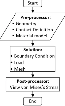
Components Size (mm) numerical static contact simulation is conducted in commercial software, ABAQUS. The simulation procedure consists of three steps: pre-processor, solution and post-processor. Detail of the simulation procedure is depicted in Figure 2.
Figure 2. Flowchart of the simulation procedure
Figure 3a, shows the position of acetabular in the hip joint system. A detailed 3-dimensional finite element (FE) model of acetabular assembly is developed as shown in Figure 3b. The femoral head was modelled as an analytical rigid. The material property of acetabular liner was modelled as a linear elastic, isotropic material based on Table 1. Boundary conditions, fixed in all directions, were applied to the outer surface of the acetabular liner. The load as listed in Table 2 was applied at the centre of the femoral head. The FE model uses 36326 solid elements, approximately 8940 nodes and use C3D4 (A 4-node linear tetrahedron) of element types, see Figure 3c.
Figure 3. Hip Joint model a) position of acetabular, b) position of load and boundary condition and c) mesh
3. Result and Discussion.
3.1. Model verifications
In the first simulation, a present finite element model was constructed based on the works of Kurtz [7]. The dimension of the femoral head and the acetabular liner are 22 mm and 39 mm, respectively with the clearances
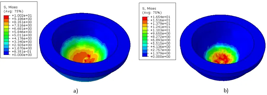
et ee the fe o al head a d the li e a e Δ i = 0.0 a d Δ i = 0.22 . Figu es a-b) depict the results of von Mises stress of the first simulation model. The von Mises stress of the acetabular liner, for a radial clearance,
Δ i = 0.22 is highe tha the o Mises st ess of the a eta ula li e fo a adial lea a e, Δ i = 0.0 . Ta le sho s
the comparison of the von Mises stress of present model and the Kurtz model [7] on the UHMWPE material. The deviation between the present model and the Kurtz model [7] is less than 5 %. It is concluded that a good agreement is found between the present model and Kurtz models [7].
In Figure 4, a stress distribution on the UHMWPE during loading is also illustrated. The highest contact stress is located at the centre of the UHMWPE whereas the low contact stress is found at its surrounding. This phenomenon shows that the critical area, which has the highest potency to fail, is located at the centre of the UHMWPE.
Figure 4. o Mises st ess a a eta ula li e ith a adial lea a e of 0.22 Δ i = 0.22 a d a eta ula li e ith a adial lea a e of 0.0 Δ i = 0.0
Load Boundary condition Femoral head
Acetabular Liner
Analytical rigid
a) b) c)
Table 4. Comparison of simulation results of von Mises stress on the acetabular liner between the present models with the Kurtz model [7].
Model von Mises stress (MPa)
∆ri =0.05 ∆ri =0.22
Present 10.02 16.54
Kurtz [8] 10.3 17.2
different 2.71% 3.83%
3.2. Results
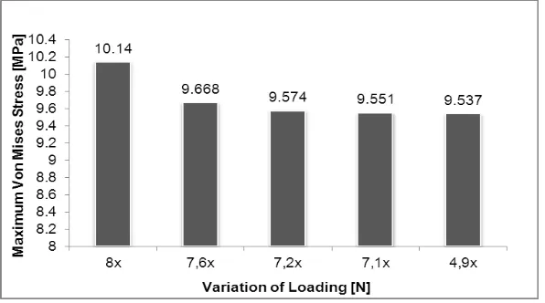
The second simulation is conducted in the present finite element model using material properties as shown in Table 1, contact loads as shown in Table 2 and dimensions as shown in Table 3. Figure 5 shows the result of the maximum von Mises stress as a function of loads variations of the human activities. The highest von Mises stress is 10.14 MPa, occurs during jumping activity. The lowest von Mises stress is 9.537 MPa, occurs during walking slowly. However, based on the present simulation, it is found that the highest von Mises stress is still below the yield stress criterion, where the yield stress of UHMWPE material is 21-28 MPa [3]. This indicates that the UHMWPE material is able to receive the various loads in the human activities.
Figure 5. Maximum von Mises stress on UHMWPE material as a function of loads variations
4. Conclusion
A finite element simulation was carried out to explore the effect of loading on contact stress of the liner and predicts the liner ability in receiving the load. The static contact of a hip joint system was used to represent the acetabular shell and liner interaction. Two simulations were conducted in this paper, namely: validation simulation and present simulation. The present model was validated with the previous model available in the literature. The results show a good agreement between the previous model and the present model. It can be concluded that the geometry modeling, mechanical properties, and simulation procedure of the present model are valid.
The second results show that the acetabular liner receives the varied von Mises contact stress during human activities. The failure analysis is conducted in von Mises stress criteria. The highest von Mises stress at the acetabular liner occurs during jumping activity. This stress does not exceed the yield stress of the UHMWPE material. It is concluded that the UHMWPE material is relatively able to carry the various loading during human activites. However, the failure of the acetabular liner can be caused by the unexpected conditions when the patient stumbles or falls down and the artificial hip joint receive unpredictable load and position.
in Laboratory for Engineering Design and Tribology, Department of Mechanical Engineering; UNDIP for his help in collecting the data in this paper.
References
[1] Anonymous. www.jbjs.org/article.aspx?Volume=78&page=755. Accessed: 20th July 2012
[2] Bartel DL, Burstein AH, Toda MD. 1985. The Effect of Conformity and Plastic Thickness on Contact Stresses in Metal Backed Plastic Implants, Journal of Biomechanical Engineering, 107, p. 193-199
[3] Kurtz SM. 2009. UHMWPE Biomaterial Handbook. Elsevier Inc., USA
[4] Dorr LD, Hilton KR. 1996. Modern metal-on-metal articulation for Total Hip Replacement. Clinical Orthopaedics and Related Research, 333: 108-117
[5] McKee GK. 1970. Development of Total Prosthetic Replacement of the Hip Joint. Clinical Orthopaedics, 72: 85-103 [6] McKee GK. 1973. The Statistics of the McKee-Farrar Method of Total Hip Replacement. Clinical Orthopaedics, 95: 26-33 [7] Kurtz SM, Giddings V, Muratoglu O, O'Connor D, Harris W, Krevolin J. 2000. Stresses in a Highly Cross-linked acetabular
component for total hip replacement. 46th Annual Meeting, Orthopedic Research Society, Orlando, Florida
[8] Yew A, Jagatia M, Ensaff H, and Jin ZM. 2003. Analysis of Contact Mechanics in McKee-Farrar Metal-on-Metal Hip Implant. Proceedings of the Institution of Mechanical Engineers. Part H: Journal of Engineering in Medicine, 217: 333-340 [9] Anthony LS, Tarun G. 2007. Hip implants VII: Finite element analysis and optimization of cross-sections, Dayton, Published
by Elsevier Inc., United States
![Figure 1. An example of a failure on acetabular liner component [1]](https://thumb-ap.123doks.com/thumbv2/123dok/1135555.654813/1.595.228.383.609.761/figure-an-example-of-failure-acetabular-liner-component.webp)