FINITE ELEMENT ANALYSIS OF REASONABLE FOUNDATION FOR SUPPORTING
SILO’S TOWER
Analisis Elemen Hingga Beberapa Tipe Fondasi Untuk Mendukung Perencanaan Tower Silo
Sukiman Nurdin
Jurusan Teknik Sipil Universitas Tadulako-Jalan Soekarno Hatta Km. 8 Palu 94118, Email : [email protected]
ABSTRACT
The limitation of soil data due to poor soil investigation process is a common problem in civil engineering project. The finite element method was used to analyse the compatibility of foundation to support silos in Liverpool Docks. Both shallow foundation and pile foundation were considered. The results of the analyses are presented by comparing analytical and numerical solution. Parametric study was considered for each case. There are different results for two types of shallow foundation that had been considered. Strip foundation seemed more reliable than pad foundation, while Pile foundation considered to be first choice due to the satisfactory condition for all factors.
Key Words: finite element, silo, shallow and pile foundation
.
ABSTRAK
Keterbatasan data tanah karena tidak dilakukannya investigasi tanah secara menyeluruh sebelum proses desain dan konstruksi adalah problem yang umum yang terjadi pada proyek-proyek teknik sipil. Metode elemen hingga adalah dipakai untuk menganalisa jenis pondasi yang dapat mendukung dari silos di Pelabuhan liverpol. Pondasi dangkal maupun pondasi tiang keduanya dipertimbangkan untuk digunakan. Analisa tersebut membandingkan metode numerik maupun analitik. Hasil dari analysa tersebut memperlihatkan hasil yang berbeda dari dua tipe pondasi dangkal. Pondasi strip memberikan nilai yang lebih optimal daripada fondasi pad. Sementara pondasi tiang menjadi pilihan pertama karena kelayakan dari semua faktor yang ditinjau.
Kata Kunci : elemen hingga, silo, pondasi tiang dan dangkal
INTRODUCTION
a. Background
Ten tower silos are used to store combined weight of approximately 3000 tonnes of load. Tower silos were erected at quayside of Alexandra docks in Liverpool.
Over the years silo builders have improved the design and construction of the above-ground portion of silos, in contrast, very little has been done to improve the foundation. Towers have generally been erected on foundations constructed by Fugro Limited. Who have the necessary technology for adequate design and constructed. The practice was reasonably successful when silos were developed. As bigger silos were erected, however, and the applied foundation pressures approached the bearing capacity of the soils, many structures settled considerably, some tilted, and some overturned completely. This digest outlines the problem and indicates the need for a soil investigation to determine the allowable bearing capacity and compressibility of the soil and thus enable proper foundation design.
b. The Problem
INFRASTRUKT
bulb do not structure wi
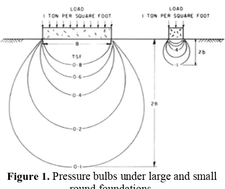
Figure 1
Non-loading has from the we centre the p in Figure 2( produce the the foundati problem is the silo ove
Figure 2.
Press Figure 2(b) close to eac the resulting will extend zone will b foundations causing the Most when a silo filling proc skeleton an voids of th
UR Vol. 2 No. 1 s caused man
eight of the pressure bulb
(a). Strong w e same effec
ion soil may remedied it rturns.
Non-uniform b
sure bulbs w , if two or m ch other. Bec
g pressure b to greater de be subjected s over this
silos to tilt t t foundation o is quickly ceeds, the lo
d to the pore he clay. Pres
1 Juni 2012 : 1
shear streng
ulbs under la foundations.
lacement o ny problems silos and the b will be dis winds acting ct. The local y cause tilting may increas
m and overla bulbs.
will overlap more silos are cause pressu bulb will be epths. The so d to higher
region wi towards each failures in loaded for th oads are app
e water cont ssures gener
‐ 8
gth of the soi
arge and sma
f silos du s. When the e live load i storted, as sh
on a tall silo overstressin g, and unless e with time
apping pressu
p, as shown e constructed ures are addi
much larger oil in the ove
stresses and ill settle m h other.
clay soils o he first time plied to the ticles and he soil. If, at th ngth is grea structure w e water pres
solidate and stable for sub In silos w p into the u reased even
shear streng ome underm
soil under h se actions can
ite Investiga
Reliable dely apprecia
ject, the gro gest risk el ect. Almos
technical inv ded to char ropriately by nager are w 2005)
Bearing c ectly related at a site, so provide infor
groundwate ngth and com The site xandra dock investigatio per foundat eholes were d
Technical As
Every ow ndation for
lding Digest nts should ucture:
Reinforced Fo A ring sses from ve circumferent e of the sil ngth, the fo el to resist s
sses. If the ufficient rein
the ring fou
reduce the ence decreas he end of loa ater than the ill be stable ssures will gain strengt bsequent load without floor
underlying s more, causin th of the soi mined when hydraulic pre n trigger a be
ations
and effectiv ated in civil e ound conditi
ement of f st exclusiv vestigation i racteristic th y how much willing to
capacity and to the engin o that a soil
rmation on er table, in mpressibility
investigation ks by Fugro on lacked dat
tion to sup drilled aroun
spects of Silo
wner should ertical wall l
tial loads tha lo. As conc undation sho such bendin
foundation s nforcement, t
undation wil
e friction b se the shear ading, the ava
e applied sh e. With time
dissipate, th th, and the s dings.
s, silage juic soil. Pore p
ng a further l. The footin the liquid fl essure. Eithe earing capac
ve site inve engineering a on is usuall financial an vely, the
is governed he subsurfac
h the client spend (M.B
d vertical se neering prop investigation
soil profile, ndex prope y.
n was carrie Limited. H ta to ensure pport the s nd the site.
o Foundatio
d insist on a proposed b CBD 81). Th red to ensu
is subject oads, soil pr at exist in the crete has a
ould be rein ng moments
should crack the monolith
ll be destro
etween soil r strength of ailable shear hear stresses, e the excess he soils will tructure will
ces normally ressures are decrease in ngs may also flow through er or both of ity failure.
estigation is and building ly given the nd technical erties of the n is required location of erties, shear
ed out along However, the a design of silos. Some
on
an adequate by Canadian he following ure a stable
ability to su be reduced.
2. Concrete It is concrete in sides are ne disturbed so
3. Centring Load footings w uniform loa full use of it Large soils to m allowable b foundations often used overturning reasons of foundation extending t contact pre uniformly a deform wou the silage on because mo silo walls th
4. Silo Grou To a constructed allowable b the minimu should be foundations should be c foundation applied ben
5. Silo Load Large contents of moisture c
upport the su
Foundation most impo a well prepa eatly trimmed oil. In granu ormwork may
laced with t n constructin y control hip is unaccep
Silo on Foot d-bearing wa whenever po ads to the fou ts allowable e foundation maintain app
bearing cap s projecting
to provide g. The interio
economy. T is normally f the silo w ed to the inn ation it could
less it is prop g pressures
stressing of h adequate r
the footing essures wou and any ten uld be reduc n the extend ost of the sila
hrough frictio not less tha s. If a smalle constructed o adequately nding momen
d
e quantities the silos are content is
uperstructure
ortant to us ared excavat d and the flo ular soils or
y be necessa the same ca ng the silo w on either ptable!
tings
alls should ossible in undation soil bearing capa ns are requir
plied pressu pacity. Larg beyond the maximum or floor is usu
The inner d slightly les all. Because ner edge ten d easily brea perly reinfor would not
the underl reinforcing, h
further insi uld be red ndency of th ced. The add
ed footing w age load is t on.
interaction essible clays acity it is rec tal clearance an the diam
r spacing is on piles or on y reinforced
nts.
of silo load e stored wet too great.
e adequately
se good qu tion in which oor cleaned o soils contai ary. The conc are as would walls. To em
r concrete
be centred order to a l and thus pe acity. red in soft, w
ures within ge-diameter
e silo walls stability ag ually omitted diameter of ss than the i e the heavy nd to deform k into indivi rced. In this be uniform ying soil c however, an de the silo, distributed m
he foundatio itional weigh would be min
transferred to
between s loaded to commended e between t meter of the desired, the n a common d to resist
d form when , i.e., when pore water ucing the sh ction with t
ngth. An imper vent any liqu ins should b uce the hyd portant that th
of the structu
Bearing Cap
The ulti ends on the depth and sh
When a ates along a c the applied nges from 0 es the shear nstant in al sotropic (var ar stress). In wn orientat ngth of as m h the strengt s imperative, ety should b sotropy,
non-to eccentri m high wind lements. Thi ar strength of
gure 3. Attitu
hout floors, t c pressure i the foundat r pressures hear strength
the soil may
rmeable floo uids from pen e provided t drostatic pres he drains con
ure.
acity
imate beari shear streng hape of found silo overtur circular arc ( shear stres to 90 deg f r strength o ll directions ries with th nvestigations ion depende much as 35 p th measured therefore, th be included -uniform pre ic loads and ds, and to pr
is factor of f the soil. (af
ude of a silo
the liquid can into the fou
ions. They c in saturated h. In additio y further d
or should be netrating the to carry them ssures in th ntinue to fun
ing capacity gth (cu) of t dation.
rns the foun (Figure 3). T
s along the from the vert of the soil s), but gen he direction
s of marine ent reductio per cent whe in the vertic hat an adequ d to allow essures applie
d overturnin revent exces
safety is ap fter M. Bozoz
foundation a
3
n flow under undation soil can increase d clay soils, on, chemical decrease soile installed to subsoil, and m away and he silo. It is nction for the
y of soils the soil, and
ndation soil The direction e slip circle tical. In rare is isotropic nerally it is of applied clays have on in shear en compared cal direction. uate factor of for strength ed to the soil ng moments sive vertical pplied to the
INFRASTRUKTUR Vol. 2 No. 1 Juni 2012 : 1 ‐ 8
ANALYTICAL DESIGN
a. Pad Foundation
Table 1. Bearing Capacity of Pad Foundation
Layer Depth (m)
cu (kPa)
v
σ
(kPa)qult (kPa)
1 0.6 60 0.00 386.43
1 2.2 60 46.20 432.63
2 4.65 30 72.87 266.10
3 7.07 35 94.90 320.30
4 11.25 25 137.30 297.90
Settlement
The flexible Settlement Strip Foundation Settlement are:
Table 2. Settlement of Pad Foundation
Depth (m)
ρi
(mm)
ρc(centre)
(mm)
ρc(corner)
(mm)
ρc(side)
(mm)
ρdiff
(mm)
ρ(total)
(mm)
18 23 123.8 52.8 74.3 71 146
Parametric Studies
Table 3. Bearing Capacity with different strength properties of the soil
cu (kPa)
qult
(kPa) FoS Increase in FoS
40 257.62 1.31 -51%
50 322.02 1.64 -20%
60 386.43 1.97 0.0%
70 450.83 2.30 +17.0%
80 515.23 2.63 +34%
b. Strip Foundation
Table 4. Bearing Capacity of Strip Foundation
Layer Depth (m)
cu (kPa)
v
σ
(kPa)qult (kPa)
1 0.6 60 0.00 386.43
2 2.2 60 46.20 432.63
3 4.65 30 72.87 266.10
4 7.07 35 94.90 320.30
5 11.25 25 137.30 297.90
Settlement
Table 5. Settlement of Strip Foundation
Depth (m)
ρi
(mm)
ρc(centre)
(mm)
ρc(corner)
(mm)
ρc(side)
(mm)
ρdiff
(mm)
ρ(total)
(mm)
18m 18.8 118 33 59 85 137
Parametric Studies
Table 6. Bearing Capacity with different strength properties of the soil
No cu (kPa)
qult
(kPa) FoS
Increase in Bearing Capacity
1 40 223.43 2.87 -50%
2 50 279.30 3.59 -20%
3 60 335.14 4.31 0.0%
4 70 391.00 5.03 +17.0%
5 80 446.85 5.76 +34%
b. Pile Foundation Bearing Capacity
Table 7. Bearing Capacity of Single Pile
Depth (m)
Qb (kN)
Qs (kPa)
Qult (kPa)
qn
(kPa) FoS
18 108 1221 282 488 2.73
Checking by Eurocode
Rcd > qn = 678.8kN > 488kN, This is satisfactory
Settlement
Table 8. Settlement of Pile Foundation Depth
(m)
ρicentre (mm)
ρi(corner) (mm)
ρi(side) (mm)
Ρaverag (mm)
Ρ(total) (mm) 18 48 12 43 35 21
Parametric Studies
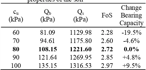
Table 9. Bearing Capacity with different strength properties of the soil
cu (kPa)
Qb (kPa)
Qs
(kPa) FoS
Change Bearing Capacity 60 81.09 1129.98 2.28 -19.5% 70 94.61 1175.80 2.60 -4.6%
80 108.15 1221.60 2.72 0.0%
90 121.64 1269.95 2.85 +4.8% 100 135.15 1316.53 2.97 +9.5%
NUMERICAL DESIGN
5
a. Pad Foundation
Table 9. Results of the finite element modelling
compared to the analytical solutions
Parameter Analytical Result
Numerical Result
Difference (%)
FoS 1.97 1.25 57
Settlement 122 44 199
Parametric Study
Bearing Capacity
Table 10. Failure load for runs with different
strength properties of the soil cu
(kPa)
Failure Load
(kN/m2) FoS
Change in Bearing Capacity 40 204 < q < 206 1.05 -19.1% 50 224 < q < 226 1.15 -8.6%
60 243 < q < 245 1.25 0.0%
70 261 < q < 263 1.34 +7.5% 80 277 < q < 279 1.42 +13.7%
Settlement
Figure 4. Settlement versus incremental loading for increasing soil strength.
Figure 5. Settlement versus incremental loading for decreasing soil strength.
b. Strip Foundation
Table 11. Results of the finite element modelling compared to the analytical solutions
Parameter Analytical Result
Numerical Result
Difference (%)
FoS 4.2 2.6 61.5
Settlement 137mm 98mm 40.0
Parametric Study
Bearing Capacity
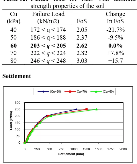
Table 12. Failure load for runs with different
strength properties of the soil Cu
(kPa)
Failure Load
(kN/m2) FoS
Change In FoS 40 172 < q < 174 2.05 -21.7% 50 186 < q < 188 2.37 -9.5%
60 203 < q < 205 2.62 0.0%
70 222 < q < 224 2.82 +7.8% 80 246 < q < 248 3.03 +15.7
Settlement
Figure 6.Settlement versus incremental loading for decreasing soil strength.
Figure 7. Settlement versus incremental loading for decreasing soil strength.
0 100 200 300 400 500
0 250 500 750 1000 1250 1500 1750 2000
Load (
k
N/
m)
Settlement (mm)
(Cu=80) Cu=70) (Cu=60)
0 100 200 300 400 500
0 250 500 750 1000 1250 1500 1750 2000
Loa
d (k
N
/m
)
Settlement (mm)
(Cu=40) Cu=50) (Cu=60)
0 50 100 150 200 250 300
0 250 500 750 1000 1250 1500 1750 2000
Loa
d (k
N
/m
)
Settlement (mm)
(Cu=80) Cu=70) (Cu=60)
0 50 100 150 200 250 300
0 250 500 750 1000 1250 1500 1750 2000
Load (
k
N/
m
)
Settlement (mm)
INFRASTRUKTUR Vol. 2 No. 1 Juni 2012 : 1 ‐ 8
c. Pile Foundation
Table 13. Results of the finite element modelling compared to the analytical solutions
Parameter Analytical Result
Numerical Result
Difference (%)
FoS 2.73 1.75 56
Settlement 21mm 19.1mm 10
Parametric Study
Bearing Capacity
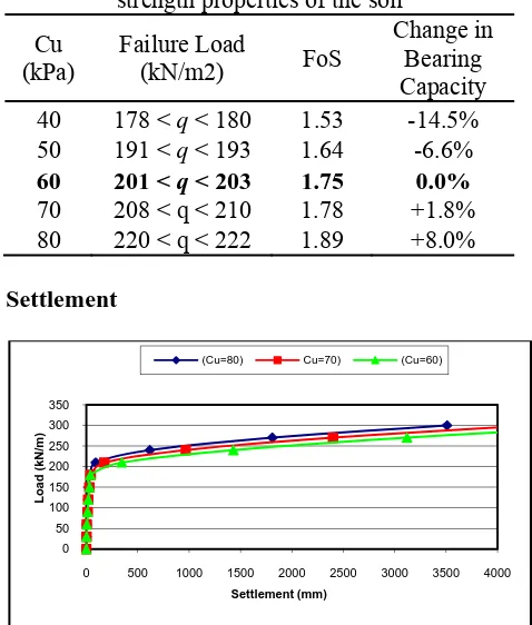
Table 14. Failure load for runs with different
strength properties of the soil
Cu (kPa)
Failure Load
(kN/m2) FoS
Change in Bearing Capacity 40 178 < q < 180 1.53 -14.5% 50 191 < q < 193 1.64 -6.6%
60 201 < q < 203 1.75 0.0%
70 208 < q < 210 1.78 +1.8% 80 220 < q < 222 1.89 +8.0%
Settlement
Figure 8. Settlement versus incremental loading for increasing soil strength.
Figure 9. Settlement versus incremental loading for decreasing soil strength.
DISCUSSION
The analytical and numerical design studies were based on the same data input. Nevertheless both of the methods usually produce different results.
a. Pad Foundation
According to the analytical and numerical predictions showed that the pad foundation seems unsatisfactory to support the silos. There are several factors base of those reason. In term of bearing capacity factor produced by analytical method shows that the value of factor safety against bearing failure is 1.92 which is lower than the limit value of failure (2.5). In addition, at the second layer of soils the value of factor of safety decreased to 1.36 which is unsatisfactory. And at the third and fourth layer the value of factor of safety was fluctuated to be 1.63 and 1.52 respectively.
The numerical result analysis appears that the value of factor of safety against bearing failure slightly lower than the analytical method. The factor of safety was produced by numerical analysis of 1.25 that it is lower than the limit value of factor of safety. It can be conclude that numerical method produces lower results than analytical design.
The settlement analysis performed by both methods showed that the settlement seemed a problem in the pad foundation. It can be seen from Table 9 that the analytical and numerical results present the settlement about 122mm and 41mm respectively. Which is the settlement is in critical condition. In addition, the difference settlement provides by analytical method is approximately 71.04 mm, that is can cause the crack on the top of foundation and will impact the stability of the silos. When the parametric study been process to decrease and increase of the strength of the soil, a change of settlement by both study are 17% and 20% respectively, where it seemed not really important effect of the settlements as shown in Table 10 and Figure 4 and 5.
As the low of factor of safety in case of pad foundation design, it seems that some factor could be a problem in the term of the pad foundation been applied. First, plastic deformation might be present due to the inconsistency of the factor of safety in several layers, leading to movement of the foundation greater than settlements; in extreme case failure will occur.
Another problem that could be occur and should be taken under consideration is the non-uniform placement of fill during filling. When the load from the content and the silos is off centre, as 0
50 100 150 200 250 300 350
0 500 1000 1500 2000 2500 3000 3500 4000
Load (
kN/
m)
Settlement (mm)
(Cu=80) Cu=70) (Cu=60)
0 50 100 150 200 250 300 350
0 500 1000 1500 2000 2500 3000 3500 4000
Load (
k
N/
m
)
Settlement (mm)
7
the result, the pressure bulb will be disorder, asshown in figure 2(a). Strong winds acting on tall silo can produce the same effect. The local overstressing of the foundation soil may cause tilting, and unless the problem is remedied it may increase with time until the silo overturns.
If two or more silos are constructed too close to each other, consequently, the pressure bulb will overlap, as shown in figure 2(b). Because of pressure are additive, the resulting pressure bulb will be much larger and will extend to greater depths. In the overlap zone, the soil will be subjected to higher stresses and the foundation in this region will be settling more, causing the silos to tilt toward each other.
The construction cost for the pad foundation will be very expensive, because it is required large amount of concrete and long time construction process. It is also required advance of site investigation to secure of stability of the silos in long-term period. And the space could be a problem for constructing the pad in the site due to the limitation of the area.
b. Strip Foundation
As can been seen from the analytical and numerical predictions, that showed the strip foundation seems feasible to support the silos in term of factor of safety. There are several factors base of those reason. In term of bearing capacity factor produced by analytical method shows that the value of factor safety against bearing failure is 4.2 which is satisfactory. In addition, at the second layer of soils the value of factor of safety decreased to 3.0 which is satisfactory. And at the third and fourth layer the value of factor of safety was consistence decrease in 3.6 and 3.5 respectively. However, the numerical result analysis appears that the value of factor of safety against bearing failure lower than the analytical method. The factor of safety was produced by numerical analysis approximately 2.6 that it is near to the limit value of factor of safety of 2.5. It seems that the numerical method produces lower results than analytical design.
The settlement analysis performed by both methods showed that the settlement is big case that really a problem in term of strip foundation been applied. It can be seen from Table 11 that the analytical and numerical results present the settlement about 137mm and 98mm respectively. Which is the settlement is in critical condition. In other hand, the difference settlement showed by analytical method is very high that it is approximately 85mm, that it is can cause the crack on the top of foundation and will impact the stability
of the structure of the silos. In extreme case can cause the failure of the silos.
As the high of the settlement and the difference settlement predicted in strip foundation design, it can be conclude that the strip foundation unfeasible for the silos. Furthermore, nine silos build in the row requires large of space along the docks, unfortunately, limited space is a problem in the site due to existing structure.
The construction cost for the strip foundation will be very expensive, because it is required large amount of concrete and long time construction process. It is also required advance of site investigation to secure of stability of the silos in long-term period.
c. Pile Foundation
According to the analytical result that pile foundation is feasible for the silos, which the settlement predicted is approximately 21mm that is can be neglected, So that the results obtained prove that the pile foundation is considered to the most feasible choice for support the silos. Furthermore, the numerical predictions showed as same as analytical prediction that the pile foundation seems satisfactory to support the silos. In the other hand, checking by Eurocode that all the conditions had been satisfied for the safety of the structure. That means that the little difference in prediction between numerical and analytical is not really significant that can affect the structure. It could be conclude as satisfactory.
In term of bearing capacity factor produced by analytical method shows that the value of factor safety against bearing failure is 2.73 which is higher than the limit value that have been given (2.5). However, at the pile group analysis, the value of factor of safety is very high approximately 9.6 which it is satisfactory. In other hand, numerical prediction is rather pessimistic where the factor of safety was presented approximately 1.75. The factor that caused the low of factor safety produce by numerical could be the lack of soil information that presented and the conservative assumption that been chosen in order to carry out the design procedure. In addition, the groundwater level was been taken rather conservative, while it has important effect on ultimate bearing capacity of foundation. With the high groundwater levels, the effective stresses in the ground are lower than when the soils immediately below the foundation are dry, and the ultimate bearing capacity is reduced.
INFRASTRUKTUR Vol. 2 No. 1 Juni 2012 : 1 ‐ 8
Table 13 that the analytical and numerical results present the settlement about 21mm and 19.1mm respectively. Which it is can be neglected. The difference about the prediction of the settlement analysis by both methods is approximately 10%.
Many types of pile for support the silos structure are available. Driven and cast in places piles are economical for land structure. But the ground heave and the vibration associated with the installation can cause destabilization of quay wall. Bored and cast in the place are the cheapest types of the pile, which it is possible to be chosen because it will keep the cost of foundation efficiently.
The construction cost for the pile foundation will be cheaper than other types of foundation, because it is not required large amount of concrete and short time construction process.
CONCLUSION
As the result of analytical and numerical design of the foundation for support the silos, there are several point that can be conclude:
The pad foundation proved to be unsuitable from any aspects of foundation design, as can been seen from the results of factor of safety against failure were unsatisfactory predicted both by analytical and numerical methods. Where it could be cause plastic deformation within the soil. Furthermore, t will lead to movement of the foundation greater than settlements; in extreme case failure will occur. Furthermore, the pad foundation will be expensive structure due to required large quantity of concrete and time consuming.
In the terms of factor of safety the strip foundation seemed to be feasible for the silos. Because the high value of factor of safety predicted by analytical methods. However, the settlement is really a critical problem that faced by strip foundation. Both numerical and analytical predicted the critical value of settlement. In addition, the difference settlement showed by analytical method is very high that it can cause the crack on the top of foundation and will impact the silo’s structure. As the high of the settlement and the difference settlement predicted in strip foundation design, it can be conclude that the strip foundation is unreliable for the silos. Furthermore, nine silos build in the row requires large of space along the docks, unfortunately, limited space is a problem in the site due to existing structure on the site.
Analytical and numerical results obtained prove that the pile foundation is considered to the most feasible choice for support the silos.
Furthermore, the numerical predictions showed as same as analytical prediction that the pile foundation seems satisfactory to support the silos. In the other hand, checking by Eurocode that all the conditions had been satisfied for the safety of the structure. Bored and cast in the place are the cheapest types of the pile, which it is possible to be chosen because it will keep the cost of foundation efficiently. The construction cost for the pile foundation will be cheaper than other types of foundation, because it is not required large amount of concrete and short time construction process.
REFERENCES
Angush J. MacDonald, 1975, Wind loading on buildings, published by Applied Science Publisher LTD.
British Standard: 8004, 1986. Code of practice for foundation. Annual book of British Standard, 1986.
Burland, J.B, and Wroth, C.P., 1974, Settlement of building and associated damage. Review paper, session V.611-54. Settlement of structures. Pentech press. London
Eurocode 7: Geotechnical Design Part 1: General Rules (ENV 1997-1)
H. Unwin & R.A Jessep, Long term pile testing in London clay: a case study. In: Proceedings of the Institute of civil engineering, Geoetechnical engineering157, Issue GE2 (2004), pp. 57-63
G.E. Barnes, 2000, Soil Mechanics: principle and practice, second edition, published by Palgrave Ltd, 2000.
M.B Jaksa et all, Towards reliable and effective site investigation, Geotechnique 55, No. 2 (2005), pp. 109-121.
M.J. Tomlinson, 1995, Foundation design and construction, sixth edition, Published by Longman Scientific & Technical.
M. Bozozuk, 1976, Tower Silo Foundations, Published by Canadian Building Digest
OASYS-GEO 17.9 Help Manual, 2002-2005.
Stewart B, 2004, Lectures Notes in Foundation Engineering, University of Glasgow.