FINITE ELEMENT ANALYSIS OF REASONABLE FOUNDATION FOR SUPPORTING SILO’S TOWER
Sukima n Nurdin*
Abstrac t
The limita tio n o f so il d a ta d ue to p o o r so il inve stig a tio n p ro c e ss is a c o mmo n p ro b le m in c ivil e ng ine e ring p ro je c t. The finite e le me nt me tho d wa s use d to a na lyse the c o mp a tib ility o f fo und a tio n to sup p o rt silo s in Live rp o o l Do c ks. Bo th sha llo w fo und a tio n a nd p ile fo und a tio n we re c o nside re d. The re sults o f the a na lyse s a re p re se nte d b y c o mp a ring a na lytic a l a nd nume ric a l so lutio n. Pa ra me tric stud y wa s c o nside re d fo r e a c h c a se . The re a re d iffe re nt re sults fo r two typ e s o f sha llo w fo und a tio n tha t ha d b e e n c o nsid e re d. Strip fo unda tio n se e me d mo re re lia b le tha n p a d fo unda tio n, while Pile fo unda tio n c o nside re d to b e first c ho ic e due to the sa tisfa c to ry c o nd itio n fo r a ll fa c to rs.
Ke y words : Finite Ele me nt, Silo , sha llo w a nd p ile Fo und a tio n.
Abstrak
Ke te rb a ta sa n d a ta ta na h ka re na tid a k d ila kuka nnya inve stig a si ta na h se c a ra m e nye luruh se b e lum p ro se s d e sig n d a n ko nstruksi a d a la h p ro b le m ya ng um um ya ng te rja d i p a d a p ro ye k-p ro ye k te knik sik-p il. Me to d e e le m e nt hing g a a d a la h d ik-p a ka i untuk m e ng a na lisa je nis k-p o nd a si ya ng d a p a t m e nd ukung d a ri silo s d i Pe la b uha n live rp o l. Po nd a si d a ng ka l m a up un p o nd a si tia ng ke d ua nya d ip e rtim b a ng ka n untuk d ig una ka n. Ana lisa te rse b ut m e m b a nd ing ka n m e to d e num e ric m a up un a na litik. Ha sil d a ri a na lysa te rse b ut m e m p e rliha tka n ha sil ya ng b e rb e d a d a ri d ua tip e p o nd a si d a ng ka l. Po nd a si strip m e m b e rika n nila i ya ng le b ih o p tim a l d a rip a d a fo nd a si p a d . Se m e nta ra p o nd a si tia ng m e nja d i p iliha n p e rta m a ka re na ke la ya ka n d a ri se m ua fa c to r ya ng d itinja u.
Kata Kunci : Ele m e n Hing g a , Silo s, Po nd a si tia ng d a n p o nd a si d a ng ka l
1. Background
Te n to we r silo s a re use d to sto re c o m b ine d we ig ht o f a p p ro xim a te ly 3000 to nne s o f lo a d . To we r silo s we re e re c te d a t q ua ysid e o f Ale xa nd ra d o c ks in Live rp o o l.
O ve r the ye a rs silo b uild e rs ha ve im p ro ve d the d e sig n a nd c o nstruc tio n o f the a b o ve -g ro und p o rtio n o f silo s, in c o ntra st, ve ry little ha s b e e n d o ne to imp ro ve the fo und a tio n. To we rs ha ve g e ne ra lly b e e n e re c te d o n fo und a tio ns c o nstruc te d b y Fug ro Limite d . Who ha ve the ne c e ssa ry te c hno lo g y fo r
1.1 The p ro b le m
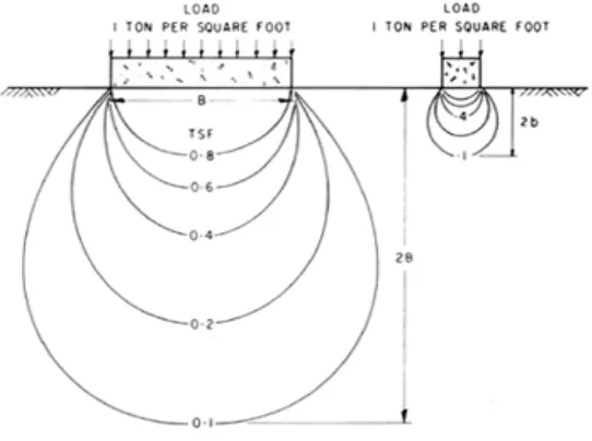
Ma ny to we r silo s c o nstruc te d o n c la y so ils ha ve ring -sha p e d c o nc re te fo und a tio ns. To re d uc e c o sts, c o nc re te flo o rs a re se ld o m p ro vid e d . Whe n the silo s a re d e ve lo p e d fo r a ny p urp o se s, p a rt o f the lo a d is tra nsm itte d thro ug h the c ylind ric a l wa lls to the fo o ting s a nd the re m a ind e r is c a rrie d d ire c tly b y the so il insid e the ring fo und a tio n. The und e rlying c la ys c o m p re ss ve rtic a lly und e r the we ig ht o f the lo a d e d struc ture in suc h a wa y tha t the a p p lie d lo a d s a re d istrib ute d unifo rmly to the so il o ve r the who le a re a e nc lo se d b y the c irc ula r fo und a tio n. This unifo rm p re ssure is d istrib ute d to the fo und a tio n so il in the fo rm o f a p re ssure b ulb ; its size a nd sha p e , d e te rmine d b y e la stic the o ry, a re re la te d d ire c tly to the d ia m e te r o f the lo a d e d a re a a s sho wn in Fig ure 1.1. He re , two fo o ting s o f d iffe re nt size
c a rry the sa m e unifo rm lo a d , b ut the p re ssure b ulb und e r the la rg e r fo und a tio n is m uc h la rg e r a nd d e e p e r. In e a c h c a se the m a xim um ve rtic a l p re ssure o c c urs im m e d ia te ly b e lo w the fo o ting a nd d im inishe s to 10 p e r c e nt o f this va lue a t a d e p th e q ua l to twic e the d ia m e te r o f the fo und a tio n. If the a p p lie d stre sse s within the b ulb d o no t e xc e e d the she a r stre ng th o f the so il the struc ture will b e sta b le .
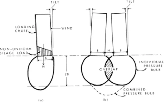
No n-unifo rm p la c e m e nt o f silo s d uring lo a d ing ha s c a use d m a ny p ro b le m s. Whe n the lo a d fro m the we ig ht o f the silo s a nd the live lo a d is o ff c e ntre the p re ssure b ulb will b e d isto rte d , a s sho wn in Fig ure 1.2(a ). Stro ng wind s a c ting o n a ta ll silo c a n p ro d uc e the sa m e e ffe c t. The lo c a l o ve rstre ssing o f the fo und a tio n so il m a y c a use tilting , a nd unle ss the p ro b le m is re m e d ie d it ma y inc re a se with tim e until the silo o ve rturns.
Fig ure 2. No n-unifo rm a nd o ve rla p p ing p re ssure b ulb s.
Pre ssure b ulb s will o ve rla p , a s sho wn in Fig ure 1.2(b ), if two o r m o re silo s a re c o nstruc te d to o c lo se to e a c h o the r. Be c a use p re ssure s a re a d d itive , the re sulting p re ssure b ulb will b e m uc h la rg e r a nd will e xte nd to g re a te r d e p ths. The so il in the o ve rla p zo ne will b e sub je c te d to hig he r stre sse s a nd the fo und a tio ns o ve r this re g io n will se ttle m o re , c a using the silo s to tilt to wa rd s e a c h o the r.
Mo st fo und a tio n fa ilure s in c la y so ils o c c ur whe n a silo is q uic kly lo a d e d fo r the first tim e . As filling p ro c e e d s, the lo a d s a re a p p lie d to the so il ske le to n a nd to the p o re wa te r c o nta ine d within the vo id s o f the c la y. Pre ssure s g e ne ra te d in the p o re wa te r te nd to re d uc e the fric tio n b e twe e n so il p a rtic le s a nd he nc e d e c re a se the she a r stre ng th o f the so il. If, a t the e nd o f lo a d ing , the a va ila b le she a r stre ng th is g re a te r tha n the a p p lie d she a r stre sse s, the struc ture will b e sta b le . With tim e the e xc e ss p o re wa te r p re ssure s will d issip a te , the so ils will c o nso lid a te a nd g a in stre ng th, a nd the struc ture will b e sta b le fo r sub se q ue nt lo a d ing s.
In silo s witho ut flo o rs, sila g e juic e s no rm a lly se e p into the und e rlying so il. Po re p re ssure s a re inc re a se d e ve n m o re , c a using a furthe r d e c re a se in the she a r stre ng th o f the so il. The fo o ting s m a y a lso b e c o m e und e rm ine d whe n the liq uid flo w thro ug h the so il und e r hyd ra ulic p re ssure . Eithe r o r b o th o f the se a c tio ns c a n trig g e r a b e a ring c a p a c ity fa ilure .
1.2 Site Inve stig a tio ns
the sila g e lo a d is tra nsfe rre d to the silo wa lls thro ug h fric tio n.
d . Silo G ro up s
To a vo id a ny inte ra c tio n b e twe e n silo s c o nstruc te d o n c o m p re ssib le c la ys lo a d e d to the a llo wa b le b e a ring c a p a c ity it is re c o m m e nd e d tha t the minim um ho rizo nta l c le a ra nc e b e twe e n the m sho uld b e no t le ss tha n the d ia m e te r o f the ring fo und a tio ns. If a sm a lle r sp a c ing is d e sire d , the silo s sho uld b e c o nstruc te d o n p ile s o r o n a c o m m o n m a t fo und a tio n a d e q ua te ly re info rc e d to re sist the a p p lie d b e nd ing m o m e nts.
e . Silo Lo a d
La rg e q ua ntitie s o f silo lo a d fo rm whe n the c o nte nts o f the silo s a re sto re d we t, i.e ., whe n the ir m o isture c o nte nt is to o g re a t. In to we r silo s c o nstruc te d witho ut flo o rs, the
liq uid c a n flo w und e r hig h hyd ro sta tic p re ssure into the fo und a tio n so il a nd und e rmine the fo und a tio ns. The y c a n inc re a se the p o re wa te r p re ssure s in sa tura te d c la y so ils, re d uc ing the she a r stre ng th. In a d d itio n, c he m ic a l re a c tio n with the so il m a y furthe r d e c re a se so il stre ng th.
An im p e rm e a b le flo o r sho uld b e insta lle d to p re ve nt a ny liq uid s fro m p e ne tra ting the sub so il, a nd d ra ins sho uld b e p ro vid e d to c a rry the m a wa y a nd re d uc e the hyd ro sta tic p re ssure s in the silo . It is im p o rta nt tha t the d ra ins c o ntinue to func tio n fo r the life o f the struc ture .
1.4 Be a ring C a p a c ity
The ultima te b e a ring c a p a c ity o f so ils d e p e nd s o n the she a r stre ng th (cu) o f the so il, a nd the
d e p th a nd sha p e o f fo und a tio n.
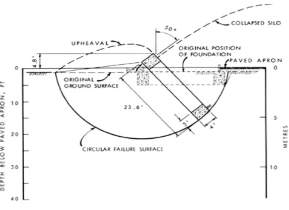
Whe n a silo o ve rturns the fo und a tio n so il ro ta te s a lo ng a c irc ula r a rc (Fig ure 2.1). The d ire c tio n o f the a p p lie d she a r stre ss a lo ng the slip c irc le c ha ng e s fro m 0 to 90 d e g fro m the ve rtic a l. In ra re c a se s the she a r stre ng th o f the so il is iso tro p ic (c o nsta nt in a ll d ire c tio ns), b ut g e ne ra lly it is a niso tro p ic (va rie s with the d ire c tio n o f a p p lie d she a r stre ss). Inve stig a tio ns o f m a rine c la ys ha ve sho wn o rie nta tio n d e p e nd e nt re d uc tio n in she a r stre ng th o f a s m uc h a s 35 p e r c e nt whe n c o m p a re d with the stre ng th m e a sure d in the ve rtic a l d ire c tio n. It is im p e ra tive , the re fo re , tha t a n a d e q ua te fa c to r o f sa fe ty sho uld b e inc lud e d to a llo w fo r stre ng th a niso tro p y, no n-unifo rm p re ssure s a p p lie d to the so il d ue to e c c e ntric lo a d s a nd o ve rturning m o m e nts fro m hig h wind s, a nd to p re ve nt e xc e ssive ve rtic a l se ttle m e nts. This fa c to r o f sa fe ty is a p p lie d to the
she a r stre ng th o f the so il. (a fte r M. Bo zo zuk, 1976)
2. Analytical Design
2.1 Pa d Fo und a tio n
Ta b e l 1. Be a ring C a p a c ity o f Pa d Fo und a tio n
Layer
Depth
(m) cu
(kPa)
v
σ
(kPa) qult
(kPa)
1 0.6 60 0.00 386.43
1 2.2 60 46.20 432.63
2 4.65 30 72.87 266.10
3 7.07 35 94.90 320.30
4 11.25 25 137.30 297.90
Se ttle m e nt:
Ta b le 2. Se ttle m e nt o f Pa d Fo und a tio n
Depth (m)
ρi
(mm)
ρc(centre)
(mm)
ρc(corner)
(mm)
ρc(side)
(mm)
ρdiff
(mm)
ρ(total)
(mm)
18 23 123.8 52.8 74.3 71 146
Pa ra m e tric Stud ie s:
Ta b le 3. Be a ring C a p a c ity with d iffe re nt stre ng th p ro p e rtie s o f the so il
cu
(kPa)
qult
(kPa) FoS Increase in FoS
40 257.62 1.31 -51%
50 322.02 1.64 -20%
60 386.43 1.97 0.0%
70 450.83 2.30 +17.0%
2.2 Strip Fo und a tio n
Ta b le 4. Be a ring C a p a c ity o f Strip Fo und a tio n
Layer
Depth
(m)
cu
(kPa)
v
σ
(kPa)
1 0.6 60 0.00
1 2.2 60 46.20
2 4.65 30 72.87
3 7.07 35 94.90
4 11.25 25 137.30
Se ttle m e nt:
Ta b le 5. Se ttle m e nt o f Strip Fo und a tio n
Depth
(m)
ρi
(mm)
ρc(centre)
(mm)
ρc(corner)
(mm)
ρc(side)
(mm)
ρdiff
(mm)
ρ(total)
(mm)
18m 18.8 118 33 59 85 137
Pa ra m e tric Stud ie s:
Ta b le 6. Be a ring C a p a c ity with d iffe re nt stre ng th p ro p e rtie s o f the so il
No cu
(kPa)
qult
(kPa) FoS
1 40 223.43 2.87
2 50 279.30 3.59
3 60 335.14 4.31
4 70 391.00 5.03
2.3 Pile Fo und a tio n
Be a ring C a p a c ity:
Ta b le 7. Be a ring C a p a c ity o f Sing le Pile
Depth
(m)
Qb
(kN) Qs
(kPa) Qult
(kPa) qn
(kPa) FoS
18 108 1221 282 488 2.73
• C he c king b y Euro c o d e
Rc d > qn = 678.8kN > 488kN, This is sa tisfa c to ry
Se ttle m e nt;
Ta b le 8. Se ttle m e nt o f Pile Fo und a tio n
Depth
(m)
ρicentre
(mm)
ρi(corner)
(mm)
ρi(side)
(mm)
Ρaverag
(mm)
Ρ(total)
(mm)
18 48 12 43 35 21
Pa ra m e tric Stud ie s:
Ta b le 9. Be a ring C a p a c ity with d iffe re nt stre ng th p ro p e rtie s o f the so il
cu
(kPa)
Qb
(kPa)
Qs
(kPa)
FoS
Change Bearing Capacity
60 81.09 1129.98 2.28 -19.5%
70 94.61 1175.80 2.60 -4.6%
80 108.15 1221.60 2.72 0.0%
90 121.64 1269.95 2.85 +4.8%
3. Numerical Design
In this c ha p te r the d e sig n o f typ e s o f fo und a tio n in the p re vio us c ha p te r will b e re vie we d a nd e xa m ine d using the finite e le m e nt a p p ro a c h with the he lp o f a c o m p ute r p ro g ra m m e SAFE in O ASYS-G EO 17.9. The inp ut a nd o utp ut
p a ra m e te rs a re the sa m e a s the p a ra m e te rs in the a na lytic a l d e sig n. A stud y a b o ut va ria tio n o f p a ra m e te rs a nd c o nve rg e nc e stud y will b e p ro d uc e .
3.1 Pa d Fo und a tio n
Ta b le 10. Re sults o f the finite e le m e nt m o d e lling c o m p a re d to the a na lytic a l so lutio ns
Parameter Analytical
Result
Numerical Result
Difference (%)
FoS 1.97 1.25 57
Settlement 122 44 199
Pa ra m e tric Stud y:
• Be a ring C a p a c ity
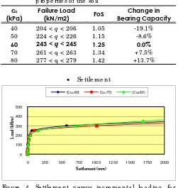
Ta b le 11. Fa ilure lo a d fo r runs with d iffe re nt stre ng th p ro p e rtie s o f the so il
cu
(kPa)
Failure Load
(kN/m2) FoS
Change in Bearing Capacity
40 204 < q < 206 1.05 -19.1% 50 224 < q < 226 1.15 -8.6%
60 243 < q < 245 1.25 0.0%
70 261 < q < 263 1.34 +7.5%
80 277 < q < 279 1.42 +13.7%
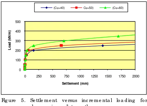
• Se ttle m e nt
0 100 200 300 400 500
0 250 500 750 1000 1250 1500 1750 2000
Loa
d (
k
N
/m
)
Settlement (mm)
(Cu=80) Cu=70) (Cu=60)
0 100 200 300 400 500
0 250 500 750 1000 1250 1500 1750 2000
Lo
a
d
(
k
N
/m
)
Settlement (mm)
(Cu=40) Cu=50) (Cu=60)
Fig ure 5. Se ttle m e nt ve rsus inc re m e nta l lo a d ing fo r d e c re a sing so il stre ng th
3.2 Strip Fo und a tio n
Ta b le 12. Re sults o f the finite e le m e nt m o d e lling c o m p a re d to the a na lytic a l so lutio ns
Parameter
Analytical Result
Numerical Result
Difference (%)
Fo S 4.2 2.6 61.5
Se ttle m e nt 137m m 98m m 40.0
Pa ra m e tric Stud y:
• Be a ring C a p a c ity
Ta b le 13. Fa ilure lo a d fo r runs with d iffe re nt stre ng th p ro p e rtie s o f the so il
Cu (kPa)
Failure Load
(kN/m2) FoS
Change In FoS
40 172 < q < 174 2.05 -21.7%
50 186 < q < 188 2.37 -9.5%
60 203 < q < 205 2.62 0.0%
70 222 < q < 224 2.82 +7.8%
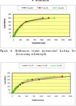
• Se ttle m e nt
0 50 100 150 200 250 300
0 250 500 750 1000 1250 1500 1750 2000
Loa
d (
k
N
/m
)
Settlement (mm)
(Cu=80) Cu=70) (Cu=60)
Fig ure 6. Se ttle m e nt ve rsus inc re m e nta l lo a d ing fo r d e c re a sing so il stre ng th.
0 50 100 150 200 250 300
0 250 500 750 1000 1250 1500 1750 2000
Loa
d (k
N
/m
)
Settlement (mm)
(Cu=40) Cu=50) (Cu=60)
Fig ure 7. Se ttle m e nt ve rsus inc re m e nta l lo a d ing fo r d e c re a sing so il stre ng th.
3.3 Pile Fo und a tio n
Ta b le 14. Re sults o f the finite e le m e nt m o d e lling c o m p a re d to the a na lytic a l so lutio ns
Parameter Analytical
Result
Numerical Result
Difference (%)
Fo S 2.73 1.75 56
Pa ra m e tric Stud y:
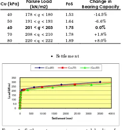
• Be a ring C a p a c ity
Ta b le 15. Fa ilure lo a d fo r runs with d iffe re nt stre ng th p ro p e rtie s o f the so il
Cu (kPa) Failure Load
(kN/m2) FoS
Change in Bearing Capacity
40 178 < q < 180 1.53 -14.5%
50 191 < q < 193 1.64 -6.6%
60 201 < q < 203 1.75 0.0%
70 208 < q < 210 1.78 +1.8%
80 220 < q < 222 1.89 +8.0%
• Se ttle m e nt
0 50 100 150 200 250 300 350
0 500 1000 1500 2000 2500 3000 3500 4000
Lo
a
d (
k
N
/m
)
Settlement (mm)
(Cu=80) Cu=70) (Cu=60)
Fig ure 8. Se ttle m e nt ve rsus inc re m e nta l lo a d ing fo r inc re a sing so il stre ng th.
0 50 100 150 200 250 300 350
0 500 1000 1500 2000 2500 3000 3500 4000
Loa
d (
k
N
/m
)
Settlement (mm)
(Cu=40) Cu=50) (Cu=60)