Control of PMS Machine in Small Electric Karting to Improve the output
Power
Didi Istardi
1,a,
Prasaja Wikanta
2,b 1Politeknik Negeri Batam, parkway st., Batam Center, Batam, Indonesia 2
Politeknik Negeri Batam, parkway st., Batam Center, Batam, Indonesia a
[email protected], [email protected] Keywords: PMSM, electric karting, power, speed control
ABSTRACT. The efficiency of control the permanent magnetized synchronous machine makes the PMSM a good choice to use as machine in electric karting. There are some research deal with this PMSM in traction drives. The intersting area of PMSM are the complecity of control of this machine. There are some technique of PMSM control such as field-oriented control, field weakening, sensorless control and digital control. The dq-represetation model use as PMSM modelling. The control of speed the machine use current regulator design with add active damping. The result shows the speed of PMSM can be use as motor and generator using field weakening and the power of PMSM can be optimized until maximum efficiency.
Introduction
PMSM have stator winding that same with induction machine and machine magnetised by magnets attached to the rotor. There are two type of magnet material that used in this machine are soft material as also known as ferromagnetic material and hard material. In this paper use NeFeB material magnet that have high magnet and difficult to demagnetised, have low dependence on temperature and the price is getting cheaper. PMSM also have high efficiency due to no losses in rotor and have quick mechanical dynamics.
One of the developments in the electric vehicle is research on electric kart racing or karting. Electric karting is a variant of an open-wheel motor sport, with small four-wheeled vehicles called karts. These karts are simple and usually raced on a scaled-down track. Since the electric kart engine is powered by an electric motor instead of an internal combustion engine and the motor is operated using the power stored in batteries, its engine has many advantages over the ICE. It is pollution-free, has higher energy conversion efficiency and less vibration, requires low maintenance, its speed is easy to control and it can use the energy from regenerative braking.
The paper is organized as follows: In the next section, a electric motor modelling was presented. The motor model was be developed in two type, steady state and dynamic modelling. The next section presents results of simulation using MATLAB®/Simulink® software and discussion of the results. Finally, the conclusions are made in last section.
Electric Motor Modelling
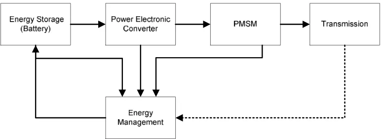
Figure 1, Karting drive system
From Fig.1, the transmission block was propulsion systems that must provide an enough effort at wheel to run the vehicle that can be called traction resistance. This traction resistance is equal to the sum of the force that overcome in rolling resistance, aerodynamic drag, climbing resistance and acceleration force.
= + + + =12 + + + (1)
where : specific air density [kg/m3] Cd : aerodynamic drag coefficient A : frontal surface area of vehicle [m2]
va : relative vehicle speed with respect to the air [m/s] Cr : rolling resistance coefficient of the wheels
m : total vehicle mass [kg]
g : gravitational acceleration [m/s2] : inclination angle [0]
The motive power that is required to run the vehicle can be calculate using
= (2)
where Pt : the motive power at wheel [W] v : wheel speed [m/s]
So, the engine torque at wheel can be find using
= ! (3)
where Tt : Torque at wheel [N.m] r : radius of wheel [m]
In this paper, the moment inertia has to be taken in analysis and the air density for this simulation is 1.225 kg/m3.
The developed torque from the electric motor can be found within the basis on energy considerations in terms of the inertias, load acceleration, coupling ratio, and the load torque or force as seen in.
= "#$#% + &$ + ' (4)
The modelling of the PMSM in Fig.1 use two type model, the steady state and dynamic modelling. The steady state modelling use losses modelling and the dynamics modelling use dq presentation.
Permanent magnet synchronous motor, the rotor can be considered magnetically round (non-salient) that has the same reluctance along any axis through the center of the machine. The one phase equivalent circuit of this motor can be seen in Figure 2.
Figure 2 Equivalent circuit of PMSM for steady state modelling
In Fig. 2 shows that the developed torque was produced by PMSM can be expressed by
= ()*+ ,-. = ()+ (5)
And the electromagnetic force voltage can be calculating using
/ =20
122
0
3 456 *$ = )$ (6)
From (5) and (6), the losses of PMSM can be calculated by
7787 = (97+7 + : = (97;()< + : (7)
In (7), the losses only depend on stator copper and iron losses. So, the efficiency of this motor can be finding using
= = $
$ + (972 ()6 + :
>?>1@@A (8)
The model of the motor in dynamic model used d-q modeling of the motor using the stator voltage equation of the motor. The d-axis is defined by the north-poles of magnets. The dq model of the motor can be seen in
Figure 3 Equivalent circuit in dq presentation
B7 = 97 7 + C7##% D $ C7 7 7E
B7E = 97 7E+ C7##% + $ C7E 7 7 + $ F (9)
the torque of this model can be calculated by
where
$ = HI= JI and
8− '=:KL MI
The torque production only support by q-axis current. The rotor magnet can be considered as a loop of constant current source, that located at the stator direct axis. The magnetic flux will effect the an induced electromagnetic force. There are no leakage inductance losses in the field. The permeability of the magnet material is almost unity so the air gap inductance seen by the stator is the same in direct and quadrature axes and also no saturation will happen inside the machine.
The power electronics converter will be used in this simulation is the standard six-switch three-phase bridge inverter converter for PMSM. This main aim of this component is to provide a suitable mean that are used in electric motor. The power electronics component as power switching device that is used in here is MOSFET (Metal Oxide Semiconductor Field Effect transistors), IGBT (Insulated Gate Bipolar Transistor), and power diode. The controller pulse is used in this simulation is the three phase pulse-width modulation (PWM). The total losses for MOSFET or IGBT for this modelling are
N = O18 +(0 RS T U 9Q VW, :+N+ O10 +Q8 RS T U +NYVW
+YN+NZ7[\% :,7[+ % ]],7[^
(11)
The power diodes losses also have two main parts, conduction and switching losses. In conduction losses, the equation is almost same with losses in MOSFET, except the duty cycle is different. It is happen because the diodes will conduct when the current through is positive and at that time the MOSFET or IGBT is off. So, the conduction losses for power diodes can be calculated by
:,_ = O18 −(0 RS T U 9Q _, :+_+ O 10 −Q8 RS T U +_Y_ (12)
In the diodes switching losses, the most important parameter is the reverse recovery losses and the rest of losses are assumed to be negligible. The switching losses of power diode can be expressed by
7[,_ = Z7[a ;Y` #+#% < ;b a + 1<a% (13)
where S : snappiness factor for diode
Result and Discussion
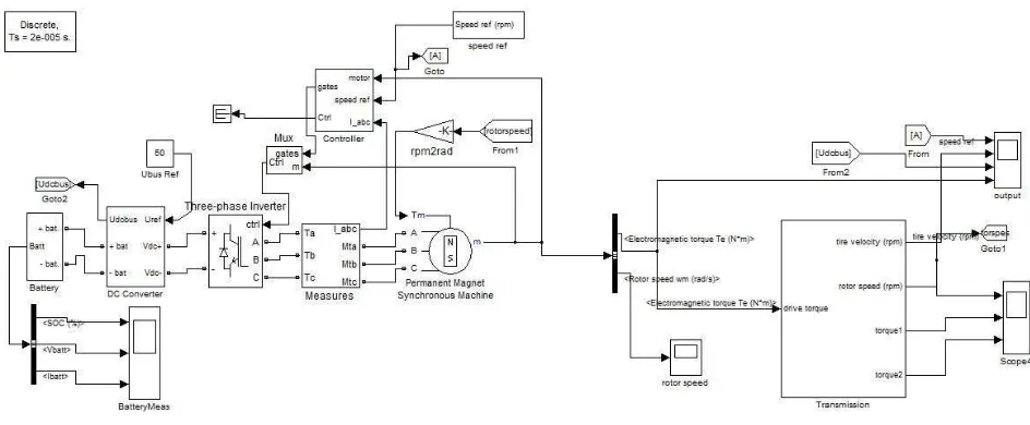
Figure 4 the drive system model in Matlab/Simulink
The main component that uses in this paper are lead acid battery – Optima D34, the motor using PMS 120 Type with 120 V ouput voltage. The selection of the power electronic converter topology and its controller depends on the selected type of a motor drive. The output of the power electronic converter is a controlled voltage that will be used to control the motor current and electromagnetic torque. Based on this output, some considerations in choosing the power electronic converter must be fulfilled.
Firstly, the current rating of the power electronic converter must be selected based on both the rms and the peak values of the required stator current. The thermal characteristic of the power electronic converter also needs to be considered because the current will produce losses in the power electronic converter and the controller. These losses will increase the temperature, while the power electronic converter has a limited range of operating temperature. Generally, the minimum rated current and voltage of the power electronic converter should be the same as for the electric motor.
The rated voltage of the power electronic converter is used to control the motor current and also the torque. Therefore, the output of the power electronic converter must be larger than the electromotive force voltage. The difference of the electromotive force voltage of the electric motor and the output of the power electronic converter produce the current and the current ripple as shown below.
From the load profile, the rms and average current rating of the power rating used in this thesis must be in the range of 75 - 160 Ampere, with variable output voltages. The converter is of 4-quadrant type, has the power of 5.5 kW and switching frequency of 10 kHz.
The result of the simulation of the power of PMSM can be seen in Fig. 5.
From this Fig.5 shown that the adding current control in PMSM improve the efficiency of the power output of the PMSM. The red line indicates the power output and the blue line indicates power input. The PMSM with current control almost have same power between input and output. With current control, the power of the machine can be run until maximum power.
Figure 6 Torque Characteristic of PMSM for electric karting
The generating torque of the PMSM alsa can be control and adjust depend of the load at the current control mode. At the normal PMSM motor, torque developed was stable.
Figure 7 Speed Characteristic of PMSM for electric karting
The Fig. 7, the characteristic of the speed is almost similiar, therefore the current control have slightly low speed. This speed characteristic can be used to add regenerative energy control. This regenerative control can supply power from the transmission that will be charge the battery. The result of adding regenerative control can be seen in Fig.8
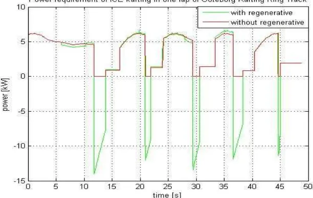
The power needed to run the electric motor can be seen in Fig. 8. This figure shows that the maximum power of the load profile is 6.67 kW for less than 1 second, the minimum power is 0 kW and the average power without the regenerative braking power is 3.6 kW. If the efficiency of the transmission is assumed to be 100% and the efficiency of the motor is assumed to be 70%, the power rating of the electric motor must be higher than 5.2 kW. The maximum power in the regenerative braking is 14 kW for less than 1 second. Therefore, the regenerative braking power that will be used to recharge the battery must be limited to the maximum power of the electric motor, power electronic converter and battery. The used energy in the transmission without the regenerative braking power is 0.049 kWh in 48 seconds. If the regenerative braking energy is used for recharging the battery, the total energy in the transmission is 0.03 kWh for 48 seconds.
Conclusion
In this paper, a MATLAB®/SIMULINK® model of an PMSM karting drive system was developed. By using the efficiency model for normal and regenerative braking conditions, the models of the dynamics PMS motor, power electronic converter, and battery were also obtained.
The comparasion of the normal PMSM and current control PMSM was evaluated and the result shown that current control PMSM have a good capability and efficiency compare normal PMSM. The regenerative energy also simulated and with this energy, the total energy reduced 0.019 kWh for 48 seconds.
References
[1].Didi Istardi, Comparison of Electric Karting Modelling Using Matlab/ Simulink Software, International Journal on Advanced Science, Engineering, and Informarion Technology. Vol 1 No. 1(2011) 1-5. [2].Didi Istardi, Electric Traction Drive Modeling for Electric Karting Application Using Matlab/Simulink
Software, Jurnal Otomasi, Kontrol dan Instrumentasi, Vol 1.No.2 (2009), 7-17.
[3].Farhan A Salem, Mechantronics Designof Small Electric Vehicles; Research and Education, International Journal of Mechanical & Mechantronics Engineering. Vol. 13 No.01 (2013), 23-36. [4].B. Tabbache, A. Kheloui, and M.E.H. Benbouzid, Design and Control of the Induction Motor
Propulsion of an Electric Vehicle, IEEE VPPC (2010)
[5].N. Mohan, T.M. Undeland, W. P. Robbins, Power Electronics: Converters, Applications, and Design (3rd editions), USA: John Wiley and Sons, 2003
[6].Z. Junzhi, L. Xin, C. Shanglou, Z. Pengjun, “Coordinated control for regenerative braking system,” IEEE Vehicle Power and Propulsion Conference (VPPC), pp 1-6, Oct. 2008
[7].S.S. Williamson, A. Emadi, K. Rajashekara, “Comprehensive Efficiency Modeling of Electric Traction Motor Drives for Hybrid Electric Vehicles Propulsion Applications,” IEEE Transaction on Vehicular Technology, vol. 56, no. 4, pp.1561-1572, July 2007.