Contents lists available atScienceDirect
Case Studies in Thermal Engineering
journal homepage:www.elsevier.com/locate/csite
Mathematical modeling and simulation of a solar agricultural dryer
with back-up biomass burner and thermal storage
Elieser Tarigan
Center for Renewable Energy and Department of Electrical Engineering, Faculty of Engineering, University of Surabaya, Jl. Raya Kalirungkut, Surabaya 60292, Indonesia
Solar drying is a cost-effective and environmentally friendly method for drying agricultural products. To design a proper solar dryer for specific products, thermodynamic relations for the dryer system need to be considered. Numerical simulations are commonly used for the design and operational control of dryers. This study presents the mathematical modeling and simulation of a solar agricultural dryer with back-up biomass burner and thermal storage. Thermodynamic and numerical simulations of the solar collector and drying chamber are performed, while back-up heater (biomass burner) operation is simulated with a computationalfluid dynamics (CFD) si-mulation. For the solar collector, it was found that the presence of a glass cover significantly increases the temperature of the collector; however, increasing the number of glass covers from one to two does not significantly affect the temperature. Variation in thickness of the back in-sulation has negligible effects, especially for thicknesses over 3 cm. The results show that there is a small difference in temperature between the bottom three trays, while the temperature on the top tray is significantly higher. The CFD simulation showed that the average drying air tem-perature in the drying chamber was 56 °C, which is suitable for the drying of agricultural pro-ducts.
1. Introduction
Drying is an effective method of food or agricultural product preservation for long periods. In general, farmers face problems in having their products dried fast, efficiently, economically, and in a correct environmental fashion. Sun drying on the ground is currently the most used method. Most farmers, especially in developing countries, cannot afford to import expensive drying equipment, which is either electrically or diesel-engine driven. This causes additionalfinancial burdens of maintenance, fuel, elec-tricity, and other running expenses in addition to environmental problems. Solar drying has been well-known as a cost-effective drying method; it is widely used worldwide and is environmentally friendly.
Solar dryer systems can be classified into direct and indirect dryers. For direct dryers, solar radiation is absorbed directly by the product to be dried, while indirect dryers use solar radiation to heat the air, which thenflows through the space containing the product[1]. Indirect solar dryers employ a separate solar collector that absorbs solar radiation, converts it into thermal energy that in turn heats theflowing air, and then supplies the heated air to a chamber. A combination of direct and indirect methods is called a mixed-type dryer[2].
Based on the auxiliary energy used to operate the system, dryers are classified into active and passive dryers. Active dryers employ an external means such as fans or blowers to move the heated air from the solar collector to the drying bed, while passive dryers use
https://doi.org/10.1016/j.csite.2018.04.012
Received 20 February 2018; Received in revised form 28 March 2018; Accepted 11 April 2018
E-mail address:elieser@staff.ubaya.ac.id.
Available online 12 April 2018
only the natural movement of heated air. The drying of agricultural products involves two fundamental processes: evaporation of moisture from the surface, and migration of moisture from the interior of a substance to the surface.
To design a proper solar dryer for specific products, thermodynamic relations for the dryer system need to be considered. Several previous works involving numerical simulations have been reported. Bala and Woods[3]presented a technique for the optimization of passive solar dryers. A physical simulation was combined with a cost prediction and experimental techniques, which found the constrained minimum of the total cost per unit of moisture removal. The result of a sensitivity analysis indicated that the design geometry is insensitive to material orfixed costs. Slimani et al.[4]studied and modeled the energy performance of a hybrid pho-tovoltaic/thermal solar collector, a configuration suitable for an indirect solar dryer. The results noted the importance of certain parameters and operating conditions on the performance of the hybrid collector.
Duran and Condori[5]simulated a passive solar dryer for charqui production using temperature and pressure networks. The results indicated that the drying time can be reduced by improvements to the constructive aspects of the dryer, the thermal isolation, and the airflow that passes up and down the trays. Simate[6]presented a comparison of optimized mixed-mode and indirect-mode passive solar dryers for maize. The optimization yielded a shorter collector length for the mixed-mode dryer than for the indirect-mode dryer. Khadraoui et al.[7]studied the thermal behavior of an indirect solar dryer with the nocturnal usage of a solar air collector with phase change material (PCM). It was reported that an indirect solar dryer (ISD) with paraffin wax as an energy storage material is an effective design to yield more favorable conditions for the drying process as compared to an ISD without energy storage.
Daghigh and Abdellah[8]presented an experimental study of a heat pipe evacuated tube solar dryer with a heat recovery system. The most accurate equation for expressing the effectiveness of this dryer was obtained by using a regression analysis. Bennamoun and Belhamri[9]studied a thermal performance analysis of an indirect-type active cabinet solar dryer. Shrinkage of the products was also taken into account. The results showed that drying was affected by the collector surface, the air temperature, and the product characteristics. Bahnasawy and Shenana[10]developed a mathematical model of direct sun and solar drying of some fermented dairy products (kishk). The model was able to predict the drying temperatures across a wide range of relative humidity values. The
Nomenclature
A surface area of solar collector (m2) Ap specific surface area of products (m2m−3)
As surface area of tray (m2)
Aw surface area of the wall of chamber (m2) b width of the collector (m)
Ca specific heat of dry air (J kg−1K−1)
Cp specific heat of air (J kg−1K−1)
Cv specific heat of water vapor (J kg−1
K−1
) d depth of products in the tray (m)
gi the gravitational acceleration vector (m/s2) ha-b convective heat transfer coefficient between air
and bottom (W m−2K−1)
ha-p convective heat transfer coefficient between air and tray (W m−2K−1)
ha-w convective heat transfer coefficient between air and chamber wall (W m−2K−1)
hb convective coefficient heat transfer from back plate to theflowing air (W m−2K−1)
hp convective coefficient heat transfer from absorber to theflowing air (W m−2K−1)
hr radiative coefficient heat transfer between ab-sorber and back plate (W m−2K−1)
i order number of trays, counted from bottom (i= 1, 2, 3,…)
I solar radiation intensity (W m−2)
k turbulent kinetic energy
kw conductive heat transfer of wall (W m−2K−1)
Le latent heat of evaporation (kJ kg−1)
M moisture content of products (decimal, d.b.) ṁ air massflow rate (kg s−1)
ma air massflow rate (kg s−1)
N number of glass covers Nu Nusselt number
Tb,m mean temperature of back plate (°C) Tb,x temperature of back plate (°C)
Tf,m mean temperature of air in the collector (°C) Tf,x temperature of air in the collector (°C) Tp,m mean temperature of absorber plate (°C) Tp,x temperature of absorber plate (°C) Tsky sky temperature (°C)
T the mean temperature ′
T the temperaturefluctuation Tref the reference temperature
Tw temperature of the wall of chamber (K) u the mean velocity components
′
ui the velocityfluctuation
Ub coefficient of total heat loss from bottom surface (W m−2K−1)
Up total heat loss from top surface (W m−2K−1)
w humidity ratio of air (kg kg−1)
Greek
β the thermal expansion coefficient
ρ the density
δij Kronecker delta
ε emissivity
εg emissivity of the glass cover εp emissivity of the absorber plate
µ viscosity
model also had the capability to predict the moisture loss from the product in wide ranges of relative humidity values, temperatures, and air velocities. There are many more investigations of solar drying systems devoted to theoretical simulations[11–17].
In this study, we focus on a design method for an appropriate solar dryer with back-up biomass heater by using mathematical modeling and simulations. The designed dryer is intended to be used for drying agricultural products (e.g., candle nuts, coffee, chili, ground nuts, soybeans, and mung beans) that have high potential for using solar dryers in Southeast Asia, especially in Indonesia and Thailand[18,19]. Thermodynamic simulations of the solar collector and drying chamber are performed. In addition, a computational fluid dynamics (CFD) simulation of the air temperature and velocity inside the drying chamber in back-up biomass energy mode is performed. The key features of the solar dryer in this study are the biomass burner and back-up heating system which employing the bricks as a low cost heat storage, combination of direct and indirect type (so called mixed mode), and employing the jacket and gap enclosing the drying chamber as a hot gas passage. The features are expected to improve the viability of the solar dryer. The results from this study can be used to design and/or optimize an appropriate solar dryer with back-up biomass heater for drying agricultural products mentioned above.
2. Dryer design and components
2.1. Design considerations
Several considerations are taken into account for the design, including the types of product to be dried, the product's physical drying characteristics, the capacity and size of the dryer, and the materials for construction. The dryer designed in this study is intended for use to dry several products identified in previous works[18,19], as previously mentioned inSection 1.
The drying characteristics are some of the most important parameters for designing a solar dryer. A solar dryer designed for a certain kind of product may not be suitable for another product. Hence, the development of solar drying technology for the agri-culturalfield should begin with studying the drying characteristics of specific agricultural products. After the information on the drying characteristics of products (such as drying rate, equilibrium moisture content, and other essential parameters) are known, mathematical modeling and computer simulations can be used to predict an appropriate and economical design for a solar dryer. In this study, the results of studies on candle-nut drying characteristics, as described in[19], will be used in the simulations.
The dryer is intended for use by an individual (household) farmer; hence, its capacity and size are designed accordingly. Results from afield survey indicated that individual farmers (in this case, located in Indonesia) need to dry about 100–200 kg of candle nuts per day on average. The bulk density of fresh candle nuts is about 600 kg/m3. By using candle nuts as the main product to determine
the dryer capacity, and assuming that the drying process occurs in a thin layer with the thickness of the bed product at 3 cm, then the area of the tray should be about 11 m2. It was also estimated that the capacity of the dryer needed for other products was
ap-proximately the same.
The solar collector system is made of a zinc metal plate painted black, with a single-layer typical glass cover. The backside is insulated with mineral wool. The biomass burner and thermal storage system are made of construction bricks. The drying chamber is framed with metal bars and walled with zinc plates (internal) and an insulated wall with mineral wool (external).
2.2. Dryer construction
The main parts of the dryer are the solar collector, the biomass burner, and the drying chamber. The solar dryer design is a
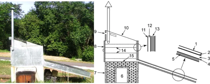
mode passive cabinet type, adopted from our previous work[2]. A photograph and schematic diagram of the dryer are shown in Fig. 1.
2.2.1. Solar collector system
The 2.75-by-1.75-m solar collector system consists of an absorber, a single-layer glass cover, a back plate, and insulation. The absorber is made from a 0.5-mm-thick black-painted metal (zinc) plate. A single layer of a typical glass cover with a thickness of 5 mm is placed on top of the collector. The backside and edges of the collector are insulated with 3-cm-thick mineral wool to reduce heat loss. The air-sealed gap between the absorber and the glass cover is 50 mm wide, and between the absorber and the back plate is a space of 100 mm. The solar collector system has a tilt of 19° from the horizontal level and faces south. This maximizes the solar radiation reception throughout the year and prevents rainwater from stagnating in the collector.
2.2.2. Back-up heater-biomass burner
A biomass burner with overall dimensions of 1.75 m × 0.9 m × 1.5 m is constructed along with the back-up heating system of the solar dryer. The wall is made from concrete, and the thermal storage space isfilled with bricks. In the biomass burner, the free space for biomass feeding is 0.75 m × 0.5 m × 1 m. The space includes a 0.75 m × 0.5 m × 0.25 m extruded wall at the outside of the burner. There is a door of 0.75 m × 0.5 m at the front side of the extruded wall. A rectangular slit of 0.1 m × 0.4 m at the lower edge of the door acts as a fresh air inlet to the burner during burning. The bricks used for heat storage are arranged in a manner in which the exhaust gas and smoke from combustion pass between all stones before venting out to the atmosphere, in order to maximize the capture of heat from the exhausted gas.
2.2.3. Drying chamber
The drying chamber is installed above the biomass burner and the thermal storage. It consists of a 19°-tilted single-layer glass cover on the top of the chamber with its trays. The trays/rack consist of four shelves with two trays on each shelf. The effective dimensions of a single tray are 1.45 m × 0.82 m. The trays are made of a perforated zinc plate and are supported with metal bars. The distance between trays is 150 mm. The bottom plate of the drying chamber is placed directly on top of the thermal storage unit. The external walls consist of 50-mm-thick insulation (mineral wool) covered with a zinc sheet. The internal walls are made of zinc sheet. A 40-mm free space between the internal and external walls forms a“jacket”around three sides of the chamber, which allows the
exhausted gas that passes through the thermal storage toflow, before it is released to the ambient area through the chimney. This keeps the drying chamber warm. The chimney is attached to the upper edge on the right side of the jacket.
Hot gas from combustion
Biomass Hot gas releases to the ambient
2.3. Dryer operation
The dryer can be operated in three different modes, i.e., (i) solar energy mode, (ii) back-up heater mode, and (iii) combination of solar energy and back-up heater mode. Thefirst mode is applied during day time when solar radiation is high enough as the heat source produced through solar collector. This mode is commonly applied for a solar dryer in general. The second mode can be used at night and/or during low solar radiation, while combination of solar energy and back-up heater (third mode) can be applied used during daytime, e.g. for continuously drying during uncertain weather condition.
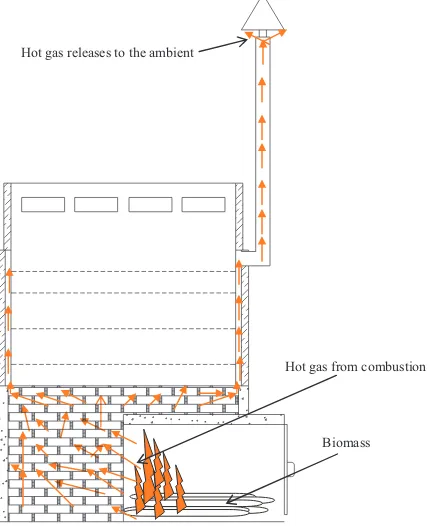
Schematic diagram operation of dryer during the biomass back-up heater mode is illustrated inFig. 2. The hot gas passes between the stored bricks,flows through the jacket, andfinally arrives at the ambient. When the combustion in the burner was over, the stored heat in the bricks might be started to contribute to the drying air. In this case, for the next day, the source of heat would be from both solar energy and stored heat in the brick (combination). It means that biomass burner and heat storage facility would improve the viability of solar dryer.
3. Prediction through modeling
Numerical simulations are commonly used for the design and operational control of dryers. Various simulation models for solar drying processes are found in the literature[3–6,9,10,15]. They differ mainly in the assumptions made and strategies employed to solve the model equation. A simplified mathematical model for the solar dryer was developed to analyze various designs in this study. The set of mathematical equations was solved by numerical simulation. In addition, a CFD simulation using FloVent was applied to predict the temperature distribution and airflow pattern in the drying chamber, especially during back-up heater operation.
3.1. Mathematical modeling
3.1.1. Thermal analysis of the solar collector system
The thermodynamic equation used for the solar collector was adopted from Ref.[22,23]. In developing the equations, the fol-lowing assumptions were made:
•
Temperatures were assumed to be uniform across the width of the collector, and the sides of the collector were assumed to be well insulated.•
The temperature gradients through the thicknesses of the plates were neglected.•
The effect of fouling on the plate was assumed to be negligible.•
The system was in a steady state.•
The temperature of the airflowing through the collector was assumed to be uniform over the entire depth of theflow channel.The terms for each notation in Eqs.(1)–(48)are described in the nomenclature list.
Considering the surface area of the solar collector (Fig. 1), and using the above assumptions, the energy balance can be written as
= + − + −
I q U Tp( p x, Ta) U Tb( b x, Ta) (1)
The heat balance on the air stream can be written as
= − + −
q h Tp( p x, Tf x,) h Tb( b x, Tf x,) (2)
The heat balance on the bottom plate gives
⎜ ⎟
To simulate the temperature distribution in theflow direction, we consider the energy balance of thefluidflowing through an element of the collector of length∆x. The useful heat gain as given in Eq.(2)is transferred to thefluid; hence
⎜ ⎟ Substituting∆qfrom Eq.(5)into Eq.(12)gives
′⋅ = − − The above differential equation can be solved using the boundary conditionTf x, =Tinatx= 0, by assuming thatF′andULare
independent ofx. The equation then gives
⎜ ⎟ Therefore, for a collector of lengthL, the outletfluid temperature is
⎜ ⎟ By integrating Eq.(13)from zero toLwe obtain the mean air temperatureTf m, :
⎜ ⎟ In the same manner, the mean top plate temperature (Tp m, ) and mean bottom plate temperature (Tb m, ) are obtained as
and =
A bL (23)
The heat loss from the top surface of the collector system takes place mainly by convection and radiation. Since the natural convection is negligibly small compared with the forced convection, the convective heat loss from the top of the collector can be written as
for wind speeds slower than 4 m/s[23].
A radiation exchange takes place between the absorber surface at the mean temperatureTp,mand the temperature sink composed of the sky and the surroundings, which a tilted collector sees as the mean temperatureTs. For simplicity,Tsis usually replaced by the sky temperatureTsky. The radiation heat loss can then be written as
= −
qrad σε hp w(Tp m4, Tsky4 ) (26)
The uppercase notation ofTrepresents the temperature in Kelvin. The sky temperature can be expressed as[23] =
Tsky 0.0552Ta1.5 (27)
The top-surface heat loss coefficient can then be derived from Eqs.(24)and(26)and written as
⎜ ⎟
It was investigated that the number of glass covers of aflat-plate solar collector system significantly affects the upward heat loss. A semi-empirical expression proposed in Ref.[23]is
= The values off andFare calculated from the following relations:
= − + ⋅ − +
f (1 0.4hw 5 10 4hw2)(1 0.056 )N (30)
= − − −
F 1 (S 45)(0.00259 0.00144 )εp (31)
Heat losses from the bottom of the collector are caused mainly by convection and can be minimized by covering the bottom with insulating material. By neglecting the heat loss by radiation, the coefficient heat loss through the bottom can be written as
∑
wherelis the thickness of the material (m), andk is the conductive heat transfer coefficient of transfer (W m−2K−1). Here, thecollector is considered to be well insulated. Thus, the heat loss from the sides, as well as from the supporting frame, can be neglected. The coefficient of heat transfer between the absorber and bottom plate inside theflow channel may be evaluated from
=
For the convective heat transfer coefficient, a suitable established Nusselt number for evaluatinghpandhbunder the conditions considered herein is not available. Therefore, the empirical equation proposed in Ref.[23]for a fully developed turbulentflow between parallel walls is adopted. The empirical equation for the Nusselt number is written as
=
Nup 0.0158 Re0.8 (34)
3.1.2. Thermal analysis for drying chamber with solar energy
The drying chamber is composed of the trays, wall, base, and roof (glass cover). In the following, equations are constructed for a steady-state situation. Such studies, as described in Ref.[24,25], propose a mathematical model for a similar drying chamber of a solar dryer. The drying rate of the product shelf can be approximately described by a representative average thin layer.
heat loss by the air. Mathematically, this can be written as Heat convection from the air to the tray = the enthalpy increase of the air owing to the increase in the moisture content + the net radiation to the bottom, the upper tray, and the cabinet wall:
⎛ For the cabinet wall surrounding the shelf, heat convection from the air to the wall = the conduction loss within the wall + the convection heat loss from the external surface of the wall to the ambient atmosphere:
⎛ For a thin layer that is being dried, the mass exchange within the product and the drying air can be derived from the equation
∂ The quantity ofδM δtp/ can be taken from the thin layer model, which is unique for a particular product[24].
3.1.2.2. Trays 2 and 3. A similar analysis for tray 1 can be applied to trays 2 and 3. Consider a typical trayiof the dryer, wherei indicates the tray's number. The energy balance can be analyzed from the following: convection from the air to the shelf + the heat convection from the air to the cabinet wall = sensible heat loss by the air.
⎛ Heat convection from the air to the shelf = the enthalpy increase of the air owing to the increase in moisture content + net radiation to other shelves and the cabinet wall:
⎛ For the cabinet wall surrounding the shelf: heat convection from the air to the wall = conduction loss within the wall + con-vection heat loss from the external surface of the wall to the ambient atmosphere:
⎛ The mass exchange within the product and the drying air can be derived from
− = ⋅
loss by the air. Heat convection from the air to the shelf + solar radiation absorbed = gain in latent heat + net radiation to tray 3, the roof, and the cabinet wall. For the cabinet wall surrounding the shelf: heat convection from the air to the wall = conduction loss within the wall + con-vection heat loss from the external surface of the wall to the ambient. Thus,
⎛ For the glass roof, heat convection from the air to the glass roof = heat convection from the roof to the ambient atmosphere + radiation to the sky + net thermal radiation to tray 4. Thus, wefind that
− = − + − + ⎛
The mass exchange within the product and drying air can be calculated from
− = ⋅
The set of Eqs.(1)–(31)above was solved to identify the output temperature of the solar collector, and the set Eqs.(35)–(48)to predict the air temperatures on the trays. Computations were made by creating a simple computer program using MATLAB. In the calculation procedure, the collector was divided into afinite number of elements/segments over which the heat loss and heat transfer coefficients were constant. The computation was started with given initial values of UL, UL’, and UL”and for thefirst segment of the collector. The material properties constants were taken from the literature[23]. The drying parameters over a range of temperatures for each tray were considered separately. In the solar drying process, most of the drying parameters (such as solar radiation, relative humidity, ambient temperature, and wind velocity) are not steady.
3.2. Simulation with FloVent
In addition to numerical simulation, a Computational Fluid Dynamics (CFD) simulation was run using the FloVent program to predict the temperature distribution and airflow pattern in the drying chamber, especially for the situation when the back-up heater (biomass burner) has to operate. The FLOVENT program uses CDF techniques to predict the airflow, heat transfer and contamination control within a room or a building[20]. The complex effects of air viscosity, buoyancy and turbulence are properly represented so that a detailed and accurate picture of both the air distribution and the consequent heat transfer process can be obtained.
The mathematical simulation offluidflow and heat transfer phenomena involves the solution of a set of coupled, non-linear, second order partial differential equations, which describe the conservation of mass, momentum and energy. By setting the boundary conditions, the resultingflow and temperature patterns are determined by solving these equations all together.
The governing equations, based on the Reynolds-averaged Navier-Stokes (Re k-ε) model for natural convectionflows[21], are
∂
Where,uis the mean velocity components (u v w, , ),ui′is the velocityfluctuation andΡis the pressure. Here,xiis the coordinate axis
(x y z, , ),ρis the density,giis the gravitational acceleration vector andβis the thermal expansion coefficient. The diffusion term is indicated by viscosityµ. The Boussinesq approximation is employed in the last term of Eq. (5.50). WhereTref=12(Th+Tc)is the
reference temperature,T is the mean temperature, andT′is the temperaturefluctuation.
The averaging process results in two new unknowns,−ρu ui′ ′j and−ρu Ti′ ′, called Reynolds terms. Thefirst term is called the
Reynolds stress (τij). The latter can be considered as a diffusion term for the enthalpy. The determination of the Reynolds terms
requires extra equations. The correlation of the Reynolds terms to the meanflowfield is resolved by turbulence models. The turbulent stresses are proportional to the mean velocity gradients:
⎜ ⎟
Whereµtis the turbulent or eddy viscosity, a property of theflow,Γtthe turbulent scalar diffusivity (also given asµ σt/ H, whereσHis
the turbulent-Prandtl number),δijthe Kronecker delta, andkis the turbulent kinetic energy.
In the CFD technique used in FloVent, the conservation equations are discretized by sub-division of the domain of integration into a set of non-overlapping, contiguousfinite volumes over each of which the conservation laws are expressed in algebraic form. These finite volumes are referred to as grid cells. The discretization results in a set of algebraic equations, each of which relates to the value of variable in a cell to its value in the nearest -neighbor grid cells. The summery of the algorithm used in FloVent for a 3D simulation offlow and heat transfer can be defined as follow:
a. initialize thefirst of pressure, temperature and velocities, b. increase outer iteration by 1,
c. set up coefficients for temperaturefield, T,
d. solve linearized algebraic equations for the value of T in each cell by performing a number of inner iterations e. repeat steps c and d forfield variables ofu, v, w, kandε
f. solve the continuity equations in similar manner and make any associated adjustments to pressure and velocities, g. check for convergence and return to step b if required.
3.2.1. Experiments with the dryer
A series of experiments with the dryer was carried out, and the results are compared with those of the simulations. Forced convection tests were carried out to investigate the performance of the solar collector. For this purpose, a centrifugal blower was applied to generate air at a certain massflow rate. The suction blower, which was positioned at the left side of the ventilation of the dryer, sucked the air out of the chamber. The air massflow rate was measured with an anemometer. A combination of handheld instruments and sensors connected to a data logger (DataTaker 605) was used to record the measurements. The temperature and solar radiation were recorded every 10 min. The solar radiation was measured with a pyranometer (Kipp & Zonen CM 3) with a sensitivity of 16.51 × 10⁻⁶V/Wm−2and an accuracy of ± 5%.
Preliminary tests indicated that the temperature profile across the width of the collector was uniform. In the test, therefore, the temperature was measured just in the centerline along the length of the collector at three points. The measurement points were located at 10 cm from the inlet side, at the center, and at 10 cm from outlet side of the collector. The temperature measurements were also measured at the bottom plate, in the air stream, and at the absorber plate.
For the drying chamber, serial tests for unloaded dryer conditions were conducted. A performance evaluation was made by varying the ratio of the energy source, i.e., including solar energy and biomass (firewood) back-up heating with heat storage.
4. Results and discussion
4.1. Solar collector
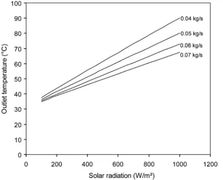
Fig. 3shows the results of the simulation on the outlet air temperature from the solar collector as a function of the solar radiation for different values of the air massflow rate, which varied from 0.04 to 0.07 kg/s-1. This range of values was reported forflat plate
types of solar air heater in the literature. The simulation results showed that with conditions of air massflow rate = 0.06 kg/s, a single glass cover, thickness of back insulator = 3 cm, andhw= 9.5 W/m2K−1, the outlet air temperature reached 60 °C at a solar
radiation of 750 W/m2.
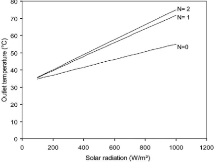
The presence of a glass cover significantly increases the temperature of the collector, as shown inFig. 4. However, increasing the number of glass covers (N) from 1 to 2 does not significantly affect the temperature. Varying the thickness of the back insulation has negligible effects, especially for thicknesses over 3 cm, as shown inFig. 5.
4.2. Comparison of simulation and experimental results
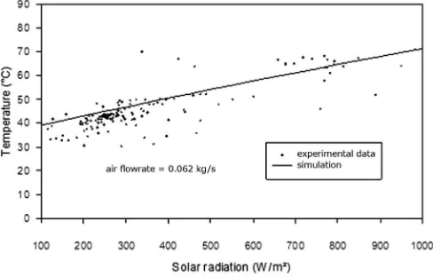
The simulation and experimental results of the solar collector system showed good agreement. The experimental and simulation results on the outlet air temperatures of the collector as a function of global solar radiation are compared inFigs. 6 and 7at airflow rates of 0.052 and 0.062 kg/s, respectively.
Fig. 8shows the experimental and simulation results on the temperature distribution of the absorber plate as functions of the global solar radiation. During the experiment, the maximum temperature of the absorber plate was found to be 110 °C at a solar radiation of 1000 W/m2. For the range of high solar radiation, the experimental results showed a lower temperature than that of the simulation. This was probably caused by heat loss, which is affected by many factors of the surroundings, as the real conditions are higher than the predicted values.
With an air massflow rate of about 0.052 kg/s, both the experimental and simulation results show that the outlet air temperature reaches 60 °C at a solar radiation of about 550 W/m2. The outlet air temperatures significantly decrease with an increasing air mass flow rate. With an air massflow rate of 0.062 kg/s and solar radiation of 550 W/m2, the outlet air temperature was reduced to 53 °C.
The results from the experiment show that the outlet air temperatures with forced convection are significantly higher than those from natural convection. The maximum temperature that can be reached with forced convection with an air massflow rate of 0.062 kg/s was about 71 °C when the solar radiation was about 950 W/m2. By contrast, with natural convection, the maximum
temperature of the outlet air was about 61 °C
4.3. Drying chamber
The main purpose of the simulation was to predict the dryer performance in order to optimize the design. In all simulation runs, the material property constants were taken from the literature[23]. The inlet air to the drying chamber is the outlet air from the solar
collector. For computational simplification, the airflow rate is assumed to be constant at 0.062 kg/s. This value is taken from the average values commonly reported in the literature for the same type of solar dryer[3,22,24], and recalculated according to the dryer size. A simulation with an empty dryer was conducted by setting the humidity ratio on each tray at a constant value.
The simulation results for the air temperature with empty trays (no load) as a function of solar radiation are shown inFig. 9. As shown inFig. 9, there is a small difference in temperature between thefirst three trays: the highest temperature is on tray 3,
Fig. 5.Effect of insulation thickness on temperature of outlet air.
Fig. 6.Comparison of experimental and predicted results for temperature distribution of outlet air of solar collector with airflow rate of 0.052 kg/s.
followed by tray 2 and then tray 1. The temperature on tray 4 is significantly higher than the temperatures on the other three trays. This is because tray 4 receives additional heat from direct solar radiation through the transparent (glass) cover on the top of the drying chamber. However, the temperature of each tray will decrease if it is loaded during the drying of products.
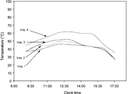
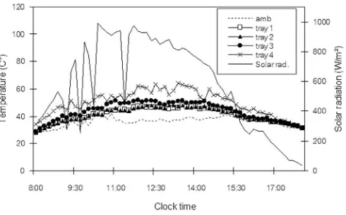
The simulation and experimental results for the air temperature on each tray are shown inFigs. 10 and 11, respectively. The process was simulated from 8:30 a.m. to 5:00 p.m. The simulation results showed good agreement with the experimental results. The input solar radiation and ambient temperature for the simulation were taken from real data for the experiment.
The maximum air temperatures were about 65°, 58°, 48°, and 45° on tray 4, tray 3, tray 2, and tray 1, respectively, owing to a solar radiation of about 1000 W/m2. In most cases, the maximal temperature coincides with the maximal solar radiation. During the
Fig. 8.Comparison of experimental and predicted results for temperatures distribution of absorber plate.
Fig. 9.Simulation results of air temperature on each tray of dryer as function of solar radiation.
experiment, it was identified that the low andfluctuating solar radiation owing to moving clouds significantly affects the air tem-peratures in the drying chamber.
A preliminary test for the solar dryer was carried out to evaluate the moisture and drying kinetics for different trays. The experiment was conducted for 24 h, with a loading of 110-kg coffee cherries. This load is about full capacity of the dryer. The experiment was started with back-up heater system mode byfirewood burning (started at 18.00), and continued with solar energy mode during day time on the next day. About 75 kg of wood with 48% (d.b.) moisture content was burned in one time feeding. The decrease of the moisture content of the product during thefirst 24 h of drying process is shown inFig. 12. The products on tray one obviously dry fastest. The moisture content was reduced from 180% to 50% (d.b.), while the moisture content of the product on the other three trays was reduced to about 58%.
4.3.1. CFD simulation
A simulation was performed using FloVent 5.2 for the back-up heater (biomass burner) operation. In the simulation, the model was simplified so that the bricks (heat storage) at the bottom and the walls of the drying chamber (excluding the doors) were assumed to be the heat source components. Owing to the limitations of the simulation program, the simulation was conducted mainly for an empty room. However, a perforated plane was set to represent each tray in the dryer.
A preliminary experiment on the designed dryer indicated that the temperature of the brick at the top level (the brick that is in contact with the drying chamber) can be sustained at an average value of about 250 °C for more than 7 h, while the temperature of the wall is about 110 °C. These values were set as the boundary conditions in the simulation.
Fig. 13(a) and (b) show the temperature contours for the cross section of the chamber from the side and from the front, re-spectively. With the conditions as simulated, the average drying air temperature in the drying chamber was found to be 56 °C. This value is suitable for the drying of agricultural products. There was a small temperature difference between the trays. However, the temperature was found to be uniform across each tray. The effect of the mesh on the trays was not studied in this work, and this might be attempted for further improvement of the model.
Fig. 13(a) and (b) show that the highest temperature occurs at the bottom edge and wall of the drying chamber. This is because the bottom plate is near (in contact with) the heat source. The lowest temperatures are found just below tray 1, which is probably
Fig. 11.Experimental results for distribution of air temperatures on each tray.
Fig. 13.CFD simulation of temperature distribution of air in drying chamber: (a) front view and (b) side view.
Fig. 14.Air speed distribution in drying chamber: (a) front view and (b) side view.
owing to the space in the path of theflow of the fresh air to the chamber. This is confirmed with high velocity as shown by air speed contours inFig. 14. In general, the average air velocity was found to be 0.13 m/s in all directions.
4.3.2. Biomass back-up heater experiment results
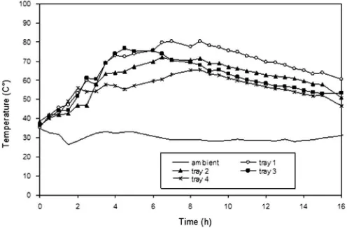
When the back-up heater burner was used, the air temperature on the trays gradually increases and reaches a maximum value after aboutfive hours from the start of wood burning as shown in Figure 6.12. This slow increase of the temperature indicates that a part of the heat from combustion was stored in the bricks when the exhaust gas and hot smoke passes through them. By burning about 75 kg of woods, the combustion could be sustained for about 4 h without adding morefirewood. Using large pieces and slow burning hardwood causes thefire to burn more slowly and last longer.
Figure 6.12 shows the temperature distribution on the dryer trays during thefirst 14 h of the test, when burning 70 kg wood. The maximum temperature that was achieved on tray two, three, and four was 71, 73, and 61 °C, respectively. For tray 1, the maximum temperature was 80 °C, which is too high for drying most types of agricultural products. However, when the trays are loaded with any product to be dried, the air temperature is certainly lower. The high temperature on tray 1 is probably due to the position of the tray close to bottom plate, which is placed directly on the top surface of bricks (heat storage). Supplying the burner with less than 75 kg wood can reduce the maximum temperature on the trays. Another experiment with burning of 60 kg of similar wood proved that the maximum temperature on the trays 4 was indeed reduced, even to 65 °C, and thus was suitable for drying most the agricultural products. However, a reduction of wood would reduce stored heat too. This was indicated by a fast decrease in temperature after the maximum value had been reached.
When the combustion in the burner was over, the stored heat in the bricks obviously started to contribute to the drying air. The temperature still gradually increased for a few hours and then decreased. When the test was started in the evening at 18.00 by supplying 70 kg of fuel woods, the temperatures on the trays in the morning of the next day remained 60, 53, 50, and 49 °C for tray one, two, three, and four, respectively, with an ambient temperature of 29 °C (Fig. 15). In this case, for the second day, the source of heat would be from both solar energy and stored heat in the brick. The bricks still continue supplying heat until midnight in the second day, and keep the temperature on tray 18 °C above the ambient temperature of about 25 °C. Again, this shows that the biomass burner and heat storage facility do indeed can improve the viability of solar dryer.
Comparing with CFD simulation for the back-up heater system, where all parameters inputs and boundary conditions are constant values and under ideal condition, it might be difficult to validate it by a real experiment. However, the simulation results would be useful for predicting the dryer performance prior to the real construction. In general, the CFD simulation results has a good agreement with the experiment results in term of temperature in the drying chamber (Fig. 12), particularly when a steady state had been reached i.e., after around eight hours of burning wood in the experiment (Fig. 15).
5. Conclusion
The mathematical modeling and simulation of a solar agricultural dryer with back-up biomass burner and thermal storage was performed. Results from the simulation of the outlet air temperature from the solar collector show that the presence of a glass cover significantly increases the temperature of the collector. However, increasing the number of glass covers from one to two does not significantly affect the temperature. Varying the thickness of the back insulation has negligible effects, especially for thicknesses over 3 cm. The simulation result with unloaded trays of the dryer shows that there is a small difference in temperature between the bottom three trays, while the temperature on the top tray is significantly higher. This is because the top tray receives additional heat from direct solar radiation.
The temperature distribution and airflow pattern in the drying chamber with a back-up biomass burner were accomplished by the Computational Fluid Dynamics method. The results show an average drying air temperature in the drying chamber of 56 °C. This value is suitable for the drying of agricultural products. Temperature differences between the trays and across each tray were found to be small. With regard to the simulation results, in general, it can be concluded that the simulated dryer conditions are appropriate for drying agricultural products.
References
[1] A.A. El-Sebaii, S.M. Shalaby, Solar drying of agricultural products: a review, Renew. Sustain. Energy Rev. 16 (1) (2012) 37–43.
[2] E. Tarigan and P. Tekasakul, A Small Scale Solar Agricultural Dryer with Biomass Burner and Heat Storage Back-Up Heater. in: Proceedings of the ISES World Congress 2007 (Vol. I–Vol. V), Berlin, Heidelberg: Springer Berlin Heidelberg, 2008, pp. 1956–1959.
[3] B.K. Bala, J.L. Woods, Optimization of natural-convection, solar drying systems, Energy 20 (4) (. 1995) 285–294.
[4] M.E.A. Slimani, M. Amirat, S. Bahria, I. Kurucz, M. Aouli, R. Sellami, Study and modeling of energy performance of a hybrid photovoltaic/thermal solar collector: configuration suitable for an indirect solar dryer, Energy Convers. Manag. 125 (2016) 209–221.
[5] G. Duran, M. Condorí, F. Altobelli, Simulation of a passive solar dryer to charqui production using temperature and pressure networks, Sol. Energy 119 (2015) 310–318.
[6] Simate, Optimization of mixed-mode and indirect-mode natural convection solar dryers, Fuel Energy Abstr. 44 (4) (. 2003) 236.
[7] A. El Khadraoui, S. Bouadila, S. Kooli, A. Farhat, A. Guizani, Thermal behavior of indirect solar dryer: nocturnal usage of solar air collector with PCM, J. Clean. Prod. 148 (2017) 37–48.
[8] R. Daghigh, A. Shafieian, An experimental study of a heat pipe evacuated tube solar dryer with heat recovery system, Renew. Energy 96 (2016) 872–880. [9] L. Bennamoun, A. Belhamri, Mathematical description of heat and mass transfer during deep bed drying: effect of product shrinkage on bed porosity, Appl.
Therm. Eng. 28 (17) (2008) 2236–2244.
[12]M.M. Morad, M.A. El-Shazly, K.I. Wasfy, H.A.M. El-Maghawry, Thermal analysis and performance evaluation of a solar tunnel greenhouse dryer for drying peppermint plants, Renew. Energy 101 (2017) 992–1004.
[13]D.K. Rabha, P. Muthukumar, C. Somayaji, Experimental investigation of thin layer drying kinetics of ghost chilli pepper (Capsicum chinense Jacq.) dried in a forced convection solar tunnel dryer, Renew. Energy 105 (2017) 583–589.
[14]M. Kumar, S.K. Sansaniwal, P. Khatak, Progress in solar dryers for drying various commodities, Renew. Sustain. Energy Rev. 55 (2016) 346–360. [15]S. Sonthikun, P. Chairat, K. Fardsin, P. Kirirat, A. Kumar, P. Tekasakul, Computationalfluid dynamic analysis of innovative design of solar-biomass hybrid dryer:
an experimental validation, Renew. Energy 92 (2016) 185–191. [16] A.E. Kabeel, M. Abdelgaied, Performance of novel solar dryer, 2016.
[17]T.A. Yassen, H.H. Al-Kayiem, Experimental investigation and evaluation of hybrid solar/thermal dryer combined with supplementary recovery dryer, Sol. Energy 134 (2016) 284–293.
[18]E. Tarigan, G. Prateepchaikul, R. Yamsaengsung, A. Sirichote, P. Tekasakul, Sorption isotherms of shelled and unshelled kernels of candle nuts, J. Food Eng. 75 (4) (2006) 447–452.
[19]E. Tarigan, G. Prateepchaikul, R. Yamsaengsung, A. Sirichote, P. Tekasakul, Drying characteristics of unshelled kernels of candle nuts, J. Food Eng. 79 (3) (2007) 828–833.
[20]https://www.mentor.com, FloVENT Overview - Mentor Graphics. [Online]. Available:〈https://www.mentor.com/products/mechanical/resources/overview/ flovent-overview-1bddfae8-40ef-4ed0-aa7a-59f1351a17d3〉. (Accessed 17 Febuary 2017).
[21]M. Promtong, P. Tekasakul, CFD study offlow in natural rubber smoking-room: i. Validation with the present smoking-room, Appl. Therm. Eng. 27 (11) (2007) 2113–2121.
[22]K.S. Ong, Thermal performance of solar air heaters: mathematical model and solution procedure, Sol. Energy 55 (2) (. 1995) 93–109. [23]J.A. Duffie, W.A. Beckman, Solar Engineering of Thermal Processes, Wiley, 2013.
[24]V.K. Sharma, S. Sharma, H.P. Garg, Mathematical modelling and experimental evaluation of a natural convection type solar cabinet dryer, Energy Convers. Manag. 31 (1) (1991) 65–73.
