CONCEPT OF ELECTRON SOURCE BASED ON PULSED PLASMA DISCHARGE Widdi Usada, Wirjoadi, Agus Purwadi, Bambang Siswanto
Technology Centre for Accelerator and Material Process (PTAPB)-BATAN Jl. Babarsari Kotak Pos 6101 ykbb, Yogyakarta 55281, e-mail : [email protected] Received 22 May 2009; received in revised form 25 June 2009; accepted 29 June 2009
ABSTRACT
CONCEPT OF ELECTRON SOURCE BASED ON PULSED PLASMA DISCHARGE. The lack of continuous electron beam machine is electron current limitation and heating impact on target. So it is needed a new machine which will give higher current in the pulsed mode operation. This paper offers on the possibility of pulsed plasma discharge as a pulse electron source. By using simple equation, it can be achieved some interesting parameters such as plasma current, rise time etc. The result is useful as basic understanding in designing this machine.
Keywords: electron source, plasma, pulse
ABSTRAK
KONSEP SUMBER ELEKTRON BERBASIS LUCUTAN PLASMA PULSA. Kekurangan mesin berkas elektron kontinyu adalah keterbatasan arus serta dampak pemanasan target, maka diperlukan adanya mesin baru yang mampu memberikan arus yang besar dan dapat dioperasikan dalam mode pulsa. Makalah ini menawarkan adanya kemungkinan lucutan plasma pulsa sebagai sumber elektron dengan menggunakan persamaan sederhana dapat diperoleh sejumlah parameter menarik seperti arus plasma, waktu bangkit dan seterusnya. Hasil ini bermanfaat sebagai pemahaman dasar untuk perancangan mesin ini
Kata kunci: sumber elektron, plasma, pulsa
INTRODUCTION
oday, accelerator has been used in wide field such as medicine, industries and environment. As an institute based on accelerator technology, we have developed many kinds of machine, such as an electron beam machine which can deliver 10 mA of electron beam current in 350 kV of operating voltage, ion implantation, neutron generator, plasma sputtering and plasma nitriding.(1) Some of them are shown in Figure 1. In general, the electron source of electron beam machine is based on filament, and it is operated continuously. The lack of this machine is that the electron beam current is limited by filament current, and because it is operated in continuous mode, the irradiated target will be heated by electron beam. Meanwhile some materials such as semiconductor material should be avoided from temperature increasing on their surface.(2) Another case, some materials need to be treated with high dose electron beam in large area. So, it is needed a new kind of electron beam machine which could be operated in pulse mode, and has a high current. In Russia, Japan and probably in several countries in the world have operated such machine and it is used, for example, to treat semiconductor material and natural rubber. This machine can deliver electron beam current up to 100 A, pulse width of 40 µ sec, energy 200 kV, repetition rate 0.1 up to 50 Hz. As an exporter country of natural rubber, actually South East Asian countries could develop such machine, and as an institute based on accelerator activity, our institute will start to develop it. There are several kinds of electron sources which could deliver high current electron beam with wide beam, for example, ribbon electron source and secondary emission electron sources, beside plasma based electron source. In this paper, it introduced a concept of electron source based on pulsed plasma discharge.
(a)
(b)
(c) (d)
Figure 1. Some pictures of home made machine at PTAPB. Electron gun based on filament (a), Electron beam machine in construction (b), Plasma Nitriding machine (c), and an automotive component is treated by plasma nitriding machine.
BASIC THEORY
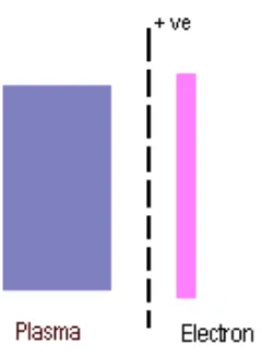
By definition that plasma consists of ion and electron, in principle, the electron of the plasma could be attracted by an electrode which has positive potential, and if this electrode is made of grid, it is expected that some of electrons pass through this grid. Figure 2 shows the extraction of electron from the plasma.
From Figure 2, it can be noted that at first, plasma is built up by a high voltage generator, and afterwards their electrons are pulled out by a positive potential grid. This method uses two generators, the first is used to generate plasma, and the second is used to pull their electron. The advantage of this type are, their generators will operate independently, and the electron beam energy can be varied, it depends on the attracting voltage. The disadvantage is that it needs some synchronization between plasma generator and the attracting voltage.
Any simple method is proposed by using only one generator. This generator has two functions, first function is to generate plasma and the second is to pull electron from plasma. The interesting property in its generator is that it should be positive pulse voltage. Figure 3 shows a working principle of such system. Though, this type is simple, but its plasma characteristic depends on generator.
Figure 3. Electron extraction by pulse positive voltage grid.
By this simple method it could be arranged an experimental circuit system, as shown in Figure 4.
Figure 4. Schematic circuit of pulse plasma discharge system
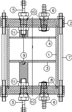
DC HV is direct current high voltage, R is charging resistor, C capacitor bank, SG Spark-Gap, D diode, and P is plasma chamber. The capacitor bank C is charged by DC HV through resistor R, and then the electrical energy of the capacitor bank is transferred to plasma chamber P by spark-gap SG through D, such that only positive voltage will pass through. Plasma chamber P represents a system which contains cathode, and grid anode, as shown in Figure 5.
CIRCUIT ANALYSIS(3)
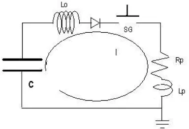
The circuit is shown in Figure 3, can be drawn in an equivalent circuit as shown by Figure 6, where C is capacitor bank, Lo is external inductance, diode D has an intrinsic resistance RD, Rp is plasma resistance, and Lp is plasma inductance
Figure 6. Equivalent circuit of pulse plasma discharge system
The equation circuit is
dt
the oscilation periode T , impedance Zand maximum current I0 will follow the next equation,
Z
And if equation (1) is arranged into normalized equation, with normalization factor are
τ
= 0,ι
= 0,∫
=+
= , 0
) 1 (
1
τ
ι
β
τ
ι
d d
d
(5)
DISCUSSION
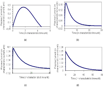
By using Watfor77 code, equation (4) has been solved numerically, and some results are shown in Figure 7 (a), (b), (c) and (d), here, it is only RD is varied, while Rp is constant. Usually, Rp is less than Z , while Z is less than RD.
(a) (b)
(c) (d)
Figure 7. Plasma current as function of time for RD =1, 5, 10, 20 .
As shown in Figure 7., for bigger RD, the rise time of plasma current will be faster, their decaying time is slower and peak current is smaller. These data will be important in designing such machine. From this figure, in order to get high current, it is recommended that RD should be 3-5 time higher than characteristic impedance Z. For higher RD, it seems that the electron sources will be inefficient, because its plasma current is too low.
(a) (b)
(c) (d)
Figure 8. Plasma current as function of time for RP = 0.01, 0.05, 0.1, 0.5
It seems that for higher RP, the plasma current will be decreased, decaying time will be longer, and rise time will be slower. So, it is resumed that for RP is smaller will increase the plasma current.
The computational result shown above has not drawn the actual machine yet, but it is useful as basic understanding in designing the machine. (4)
CONCLUSIONS
It has been shown basic principle of electron source based on pulsed plasma discharge. Using simple equation, it is shown that by varying some parameters like diode resistance and plasma resistance, some plasma characteristics like plasma current, rise time, and decaying time will be understood. Higher plasma current will impact in achieving higher electron beam current in electron source based on pulsed plasma discharge.
ACKNOWLEDGMENT
The authors would like to thank to Dr. Widi Setiawan, Head of Technology Center for Accelerator and Material Process, National Nuclear Energy Agency for initiating this concept, to Prof. Lee Sing for his invaluable efforts such as one of us (Widdi Usada) will participate this program, to Prof. C.S. Wong and Prof. R.S. Rawat for their support in inviting (Widdi Usada), and to ICTP in funding me. This work is funded under DIPA 2008, and presented in International Workshop on Plasma Focus and Future Applications” July 14-15,2008 Department of Physics, University of Malaya, Kuala Lumpur, Malaysia.
1. SUPRAPTO, Hasil Litbang Bidang Teknologi Akselerator dan Fisika Nuklir, (2008).
2. S.A., KORENEV AND R.P., JOHNSON, “Pulsed Low Energy Electron Sources For Material Surface
Modification”, in Proc. 26th Power Modulator Symposium and High Voltage Workshop, San Francisco, CA,
(2004)
3. S. LEE, “Basic Methods Of Plasma Technology”, in Proceedings of 1984 Tropical College on Applied Physics, Laser and Plasma Technology, edited by S. Lee, et al, World Scientific Publish Co. Pte, Ltd, (1985).