Electron beam extraction on plasma cathode electron sources system
Agus Purwadi, Taufik, Lely Susita R. M., Suprapto, Saefurrochman, Anjar A. H., Kurnia Wibowo, Ihwanul Aziz, and Bambang Siswanto
Citation: AIP Conference Proceedings1824, 030031 (2017); doi: 10.1063/1.4978849
View online: http://dx.doi.org/10.1063/1.4978849
View Table of Contents: http://aip.scitation.org/toc/apc/1824/1
Published by the American Institute of Physics
Articles you may be interested in
Study on the effect of atmospheric plasma processing using gas mixture on 3C-SiC AIP Conference Proceedings 1824, 030030030030 (2017); 10.1063/1.4978848
Effect of magnetic field on carbon nanotubes and graphene structure synthesized at low pressure via arc discharge process
Electron Beam Extraction on Plasma Cathode Electron
Sources System
Agus Purwadi
1,a), Taufik
1,b), Lely Susita R. M.
1, Suprapto
1, Saefurrochman
1,
Anjar A.H
1, Kurnia Wibowo
1, Ihwanul Aziz
1, Bambang Siswanto
11Centre for Accelerator Science and Technology –BATAN,
Jl. Babarsari POB 6101 Ykbb, Telp. (0274) 488435, Yogyakarta 55281, Indonesia
a)[email protected] b)[email protected]
Abstract.ELECTRON BEAM EXTRACTION ON PLASMA CATHODE ELECTRON SOURCES SYSTEM. The electron beam extraction through window of Plasma Generator Chamber (PGC) for Pulsed Electron Irradiator (PEI) device and simulation of plasma potential has been studied. Plasma electron beam is extracted to acceleration region for enlarging their power by the external accelerating high voltage (Vext) and then it is passed foil window of the PEI for
being irradiated to any target (atmospheric pressure). Electron beam extraction from plasma surface must be able to overcome potential barrier at the extraction window region which is shown by estimate simulation (Opera program) based on data of plasma surface potential of 150 V with Ueks values are varied by 150 kV, 175 kV and 200 kV
respectively. PGC is made of 304 stainless steel with cylindrical shape in 30 cm of diameter, 90 cm length, electrons extraction window as many as 975 holes on the area of (15u65) cm2with extraction hole cell in 0.3 mm of radius each
other, an cylindrical shape IEP chamber is made of 304 stainless steel in 70 cm diameter and 30 cm length. The research result shown that the acquisition of electron beam extraction current depends on plasma parameters (electron density ne,
temperatureTe), accelerating high voltage Vext, the value of discharge parameter G, anode area Sa, electron extraction
window areaSeand extraction efficiency value D.
Keywords: PGC, plasma electron beam, extraction, maximum electron
INTRODUCTION
One of the 2015 research target in Center for Accelerator Science and Technology (CAST) BATAN, Yogyakarta was the design and construction of extraction system for plasma electron beam from Plasma Generator Chamber (PGC) window of Pulse Electron Irradiator device. To support the target, it was performed the study of necessity for the electron beam extraction through the PGC window in the Plasma Cathode Electron Sources (PCES) and electron beam extraction prediction by Opera simulation program, based on the 150 V potential data of the plasma surface with extractor high voltage Ueksthat be varied from 150 kV, 175 kV and 200 kV.
The gas that was heated until the specific temperature for the material, then the atoms will be ionized into positive ion and electron. When heating was continued by increasing the voltage between both electrodes into PGC, then the number of ions and electrons increased. When it reaches a certain limit, then the charge will be in
International Conference on Plasma Science and Applications (ICPSA 2016)
equilibrium with the atoms into plasma. Quasi neutral plasma is a mixture of ions, electrons, free radicals and molecules/atoms that are sensitive to magnetic and electric fields [1].
Plasma cathode electron sources module is the pulse electron beam generator, which is formed by the electrons emission or extraction from the plasma surface in the PGC. Electron plasma was emitted out to the accelerator region through the grid holes (extraction system) that is mounted on the PGC wall. In the accelerator region, electron beam was accelerated until the maximum speed by Coulomb field using external high voltage. Here in after it was extracted towards the target passes through the foil window on the vacuum vessel wall of the Pulse Electron Irradiator (PEI). The PEI device with spacious and high current electron beam output would be very useful to be applied in the large flat materials surface. This device is very interesting to be applied in many kinds of industries such as the toxic material processing industries (natural rubber latex), surface modification in the polymer and semiconductor industries, and the food industry for pasteurization without destroying the texture and nutrition, also for the waste neutralization [2-3].
The maximum electron beam current extracted from plasma surface, determined by the existence of equilibrium discharge current between the arc discharge current (Id) with the summing of anode current (Ia) and electron
extraction current (Ie). The G of plasma discharge parameter in the PGC is determined by the use of this discharge
type, whether with corona discharge, glow discharge or arc discharge. The determination of the type of discharge will depend on the value of the trigger power supply, the plasma generator power supply and the PGC geometry size and shape. The PCES system which need high discharge current until hundreds of ampere (A) and a relatively small discharge voltage of tens volts, then the arc discharge should use the specific G values [4]. The occurrence of voltage distribution/plasma potential φp in the extraction window area, the existence of the barrier potential or
without the potential barrier can be shown from the simulation results using the Opera program with the PEI and PGC geometry and size, extraction hole diameter/grid and electron accelerated or extracted voltage as the data input.
THEORY
PGC or plasma cathode is a plasma generation devices with restrictions of which the electron is emitted or extracted. The ions and electrons extraction from the plasma does not have the same phenomenon (not just caused by the difference of extraction voltage polarity), but the key is related to how charged particles can be extracted from the plasma.
In the PCES system, the most specific condition is plasma has positive potential towards the discharge electrodes [5]. This means that ions are emitted from the plasma surface (open), but electrons have to overcome the potential barrier (M) to be able to extracted from the plasma surface towards the acceleration region. Figure 1 is the scheme of electrons extraction from the plasma surface (Mp potential) in the PCES through the emission window with Ma
potential into collector with Mk potential [6]. Figure 2 shows the scheme of the electron extraction with plasma
potential Mp through the electron beam extraction hole/window with a M barrier potential. At this condition, the
radius of emission/extraction hole re is much smaller than the sheath length ls or (re <<ls), so the emitted electron
beam je obtain the barrier potential. Figure 3 informs the scheme of the plasma electron emission without potential
barrier where at this stage, the radius of emission/extraction hole re is much greater than the sheath length ls or
(re>>ls), so the emitted electron beam current flows from the open plasma into the electrons acceleration region
without potential barrier M [7].
FIGURE 2. Scheme of the plasma electron extraction (plasma potential Mp) with potential barrier M [8].
FIGURE 3. Scheme of the plasma electron extraction (plasma potential Mp) without potential barrier M[8].
The phenomenon of the plasma electron emission/extraction on the PCEG system is more complex than ion extraction from the plasma. To form electron beam, the addition of collector potential)k or extraction voltage Ueks
must comply with the increasing of velocity (v) and power (W) for ion or electron [8]. This state is automatically met for the ion extraction from the plasma, because next the ion only accelerated by the electric field of the external accelerator, but the different condition will happen to emit or extract electron from the plasma. Electrons with relativistic velocity near ion sheath decelerated, but ion with non-relativistic movement will be accelerated. To get away from the plasma surface, electron should be able to overcome the potential barrier. Therefore the general equation for the electron current density into the collector je with relativistic particle speeds is given by Boltzmann
equation [9] as follows:
¸¸
¹
·
¨¨
©
§
e k p e
e
T
k
e
j
j
0exp
M
M
(1)
with je0 = ¼ e ne v is the maximum/thermal plasma electron current density, e = electron charge = 1.602 u 10-19 C,
φp = plasma potential, φk= collector potential, k = Boltzmann constant = 1.381 u 10-23 J/K, Te = plasma temperature,
ne = the plasma density and v = relativistic velocity of the electron.
Requirements for the emission of electron occurs from the plasma surface to the area of plasma accelerator for specific shapes and sizes of any PGC associated with a broad measure of the anode Sa (total area of anode that can
electrons is synonymous with total area of emission holes) as so as discharge parameters G used in PCES equipment. Discharge type used in the PCES system is arc discharge so that the parameter value G is in the range of 2 to 8.5 [10]. Condition to be met to enable the extraction of the maximum electron and electron acceleration occurs in the area of electron accelerator given by the equation [11].
1
a e
S
S
G
(2)The relation between G, Se and Sa in equation 2 is described in Result and Discussion chapter. Electron
extraction efficiency which is a ratio of the electron emission current of the discharge current can be written as
>
p a e@
a e
e
e
k
T
S
S
S
M
M
D
¸
¸
¹
·
¨
¨
©
§
exp
(3)Fraction of plasma electron beam passes in the middle of the open area of the plasma is much larger (higher) due to the influence of larger potential barrier in the suburban part.
METHODOLOGY
Plasma Cathode Electron Sources (PCES) system of DUET model for Pulsed Electron Irradiator (PEI) device and supporting tools of plasma power supply schematic shown in Figure 4 [12]. Anode electron extractor (the grids) are mounted on the bottom of the PGC on PCES system. They have function as an electron emission current controller plasma extracted from plasma surface [13]. Shown in Figure 4, PCES consists of two electrodes producing plasma. They have two power sources, namely (2,3,4) on the left and right PCES. Plasma producing electrode system have two power supply, namely ignitor power supply (7) and plasma generator power supply (8). The specification of ignitor power supply is 10 kV of voltage and 100 mJ of the energy. It supplies voltage through the anode (2) and through the isolator/teflon (3) and form a plasma spot (10) on the surface of the cathode (4) through the process of discharging surface of the PGC (1) with certain gas pressure. Then the spot of plasma that is formed will be dissipated by the voltage of the plasma generator power supply (8) and the dissipated plasma are accelerated. It will ionize the gas in the cavity of the plasma chamber and formed the plasma arc discharge (11) around the anode hollow of PGC. If both sides of the electrode running synchronously then the entire anode chamber will form a plasma arc discharge. By accelerating voltage (9) electron that pass through the grid (5) will be accelerated up to be able to penetrate the window foil (6) which is subsequently used for the irradiation of samples (material surface).
FIGURE 4. PCES system schematic of DUET models [12]: 1 – Plasma Generator Chamber (PGC), 2 – Ignitor electrode, 3- Isolator/Teflon, 4-Cathoda, 5-Grid, 6-Foil window, 7-Ignitor power supply, 8-Plasma generator power supply, 9-Accelerator high
voltage, 10-Spot plasma, 11-Arc discharge plasma.
the plasma chamber. Having obtained a plasma spark further known requirements of the plasma arc discharge by plasma arc discharge that exist in the plasma generator electrode. Arc discharge plasma in the plasma generator electrode must also fulfil the requirements of specified breakdown voltage in addition to a large voltage to the electrodes mounted plasma generator, also the distance between the plasma generator anode with ignitor electrode, as well as the gas pressure in the plasma generator [14]. Ignitor electrodes (on the right and the left side) is equipped with a plasma generator power supply system discharge ignitor (Ignitor Discharge Power Supply/IDPS) which supplies voltage 10 kV, 100 mJ; and a plasma generator electrode connected to the Arc Discharge Power Supply (ADPS) supplies 1 kV for generating a plasma arc discharge with a large current (5-10) A and pulse width (10-100) μs.
Seand Saextent size should be determined in advance so as to explore whether the use of Se and PGC size related
to the Savalue has qualified for the maximum electron beam extraction/saturation from the plasma surface to the
region of electron beam accelerator. Elaboration relation to the terms of the parameter extraction condition can be done by using the law of conservation of stream discharge or discharge current equilibrium on PCES system such as equation [2] which is a condition for the existence theoretically extraction can be justified.
Shown in the theory chapter (Figure 2 and 3) that the fraction of the electron beam plasma passes in the middle of the open plasma area is much larger (higher) than at the periphery holes emissions, this can be demonstrated by observing the distribution of equipotential plasma in the hole extraction of electron on the wall of BGC are approximate simulation (Opera program) on the basis of data usage surface potential of plasma at 150 volt by varying the high voltage accelerator Uekswhich varied from 150 kV, 175 kV and 200 kV. PGC is made of 304
stainless steel cylindrical shape with Ф= 30 cm of diameter and l= 90 cm of length, window extraction of electrons measuring (15u65) cm2with along the side window extracting these electrons there are a number of 15 holes grid
with radius of r= 0.3 mm respectively, IEP chamber is made of 304 stainless steel cylindrical shaped with Ф= 70 cm of diameter and l= 130 cm of length.
RESULTS AND DISCUSSION
Shown in equation (1) that the electron current density je will be maximum if the plasma potential is equal with collector potential φkor je = je0. The state of electron current density saturation jecan be occurred when emission
hole radius re almost equal in length to the thickness of sheath (sheath charge) ls that is re ≈ ls, the electrons leave
plasma from open plasma surface either without or with through potential barrier.
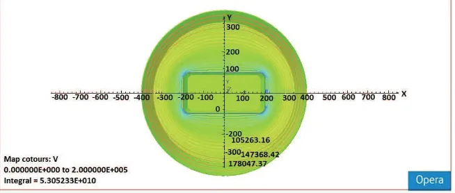
Shown in Figure 5 that the cross-section of potential space of Pulsed Electron Irradiation (PEI) chamber in cylindrical shape with Ф= 70 cm of diameter and l= 130 cm of length. The Plasma Generator Chamber (PGC) in cylindrical shape with diameter of Ф= 30 cm and length l= 90 cm which is made of 304 stainless steel material on PEI chamber with at the bottom is made of electron extraction window and the windows area is (15x65) cm2. In
Figure 6 is shown by the number of grid holes as many as 15 holes on the bottom of PGC wall along side of window with an area of electron extraction (15 x 65) cm2and size of each hole radius is r= 0.3 mm. There are 975 holes of
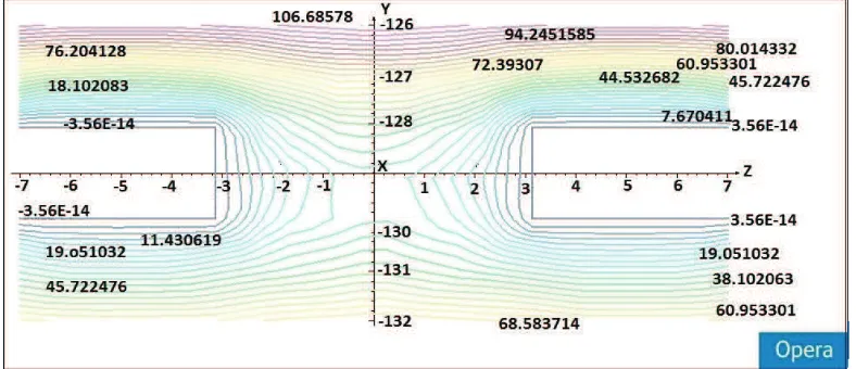
electron extraction in the electrons extraction window area. In Figure 7 is shown the equipotential line distribution of radial direction in single grid hole of plasma surface (radius r= 0.3 mm) using an extractor high voltage 150 kV which is in these conditions still occurs potential barrier, so the electrons extraction current from the plasma surface to the acceleration area has not happened.
FIGURE 6. The grid holes as many as 15 hole along side of the area extraction window(15x65) cm2with radius size of each hole
r= 0.3 mm.
FIGURE 7. The equipotential line distribution of radial direction in single grid hole of plasma surface (r= 0.3 mm) for the extractor voltage 150 kV (potential barrier exist).
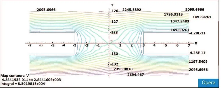
In Figure 8 is shown the equipotential line distribution with radial direction of plasma surface on single grid hole (r= 0.3 mm) using an extractor voltage of 175 kV, it appears that despite the extractor voltage has been raised by 25 kV, however on this condition still occurs a potential barrier, so that electrons extraction current from plasma surface to acceleration area has not been happened. This means that each condition in Figure 7 and Figure 8, the magnitude of potential barrier is still equivalent with the electron beam current energy to the anode, thus je=ja.
Furthermore, in Figure 9 is shown the equipotential line distribution with radial direction of plasma surface on single grid hole (r= 0.3 mm) at extractor voltage of 200 kV. In this condition it has been occurred the flow of electrons current extraction on each extraction hole due to potential barrier has been overcome with the additional extractor voltage 25 kV (it is occurred the equipotential line that intersect between plasma equipotential line φpwith
extractor equipotential line φk). Shown in Figure 9, electrons extracted from the open plasma surface when φkis
equal with φp, so from equation (1) can be obtained current density of electron emission jeequal to current density of
saturated electron beam j0or je=j0, which is certainly the electrons current density jegreater than the current density
of anode ja(currently before the voltage extractor achieve Vk = 200 kV) and efficiency of electrons extractionαin
this condition in accordance with the equation (3) that depends on magnitude of Se,Saand extractor high voltage Vk
(which affects the value of plasma parameters).
FIGURE 9. The equipotential line distribution with radial direction of plasma surface on single grid hole (r= 0.3 mm) to the extractor voltage 200 kV (without potential barrier).
In the previous chapter, some theory have explained that to condition the flow of thermal emission of electrons from the plasma surface to the acceleration region can be obtained by the conservation laws of discharge currents that occur on the system of Plasma Cathode Electron Source (PCES). The conservation law of currents discharge showed that the electrons fraction from current of arc plasma discharge in CGP Idconsists of anode current Ia=jaSa
and electron extraction currentIe=jeSeor Id=jaSa+jeSe, thus from the equation (1) the arc discharge current Idcan
with
G
j
e0S
aI
d is a constant discharge parameters (the value of Gdepends on the type of discharge).The electrons current density iaandie that can be written as
Substitution of equations (6a) and (6b) to the equation (5) will be obtained the equation ofThe equation (5) can also be written in another form
Substitution equation (6b) to the equation (8), will be obtained as
or the electrons current density from the anode to the collector ie can be written as
The total of electrons beam current Ie extracted from Se hole is
1
%
a e
S
S
G
(15)
Equation (15) that occurs when Mk = Mp, the maximum of electron beam current Ie is similar to equation (2) which
is a requirement that must be fulfilled for the maximum electron extraction from the extraction hole. It can be concluded that in order to obtain the maximum electrons current extraction of plasma surface, therefore equation (15) must be fulfilled with potential barrier in extraction hole area, and then in the area extraction hole will be eliminated which in theory is shown in Figure 3 in which the electrons extracted from plasma surface (open) to the acceleration area.
Electron current density is extracted equal to maximum current density/plasma saturation (je = j0), which je is
greater than anode current density ja (before the extractor voltage is increased). Extraction process of plasma
electron beam in the absence of such a potential barrier in the simulation is shown in Figure 9 which is by input data using plasma surface potential of 150 V to the magnitude of extractor voltage Ueks= 200 kV. PGC is used SS
material in cylindrical shape with Ф = 30 cm of diameter and l = 90 cm of length, the extraction window of electron beam as many as 975 holes in the area (15x65) cm2 with radius of each extraction hole cell r = 3 mm, PEI chamber
used materials SS in cylindrical shape with Ф = 70 cm of diameter and l = 130 cm of length.
Extraction process of electron beam plasma in Figure 3 and Figure 9 does not apply to the equation (15) for the opposite state that if G Se/Sa > 1, due to the situation, collector potential Mk, will never reach or exceed the value of
plasma potential Mp. Even though the potential addition of Mk being implemented and followed by a potential
increase in plasma Mp, however constantly obtained Mk value is smaller than the plasma potential Mp or constantly Mk
<Mp. Thus the electron beam going towards to collector constantly through a potential barrier and electrons
accelerated will never occur. The conditions when equation (15) is not fulfilled, thus the theory of electron plasma extraction process (with a barrier potential M) is shown in Figure 2 and approximate simulation (Opera program) are shown in Figure 7 and Figure 8.
CONCLUSION
Extraction of electron beam on PCES system in area near the extraction hole electron movement is slowed by the presence of potential barrier, can be represented by approximate simulation (Opera program) based on the plasma voltage as value as V = 150 volt with using variation of the extractor high voltage values from 150 kV up to 200 kV. Electron beam extraction occurs only if fulfilled the formula requirements of G (Se/Sa) < 1 where G is a constant
parameter plasma discharge, Se is spacious collectors subjected to electron beam and Sa is spacious anode subjected
electron beam. The third parameter values of G, Se and Sa are an absolute must be known in the electron extraction
process, remember that the α value extraction efficiency also depend on Se and Sa besides the extractor high voltage
Ueks (affecting plasma parameter values).
ACKNOWLEDGEMENTS
The authors would like to thank to the head of PSTA BATAN office that has funded this research through funding DIPA 2015 and also Prof. Efim Oks which has provided knowledge of the theory and technology of electrons extraction in the system PCES as well as to all members of the group PCES PSTA-BATAN; Prof. Sudjatmoko, Drs. Widdi Usada, Ir. Wiryoadi, Drs. Budi Santoso MT, Drs. Aminus Salam, Heri Sudarmanto, Untung Margono, Agus Wijayanto and Badi Wiyono, for all input and suggestions at the weekly coordination meeting so that this paper can be finished.
REFERENCES
1. Sudjatmoko, dkk., Uji Fungsi Perangkat Sistem Sumber Elektron Katoda Plasma Untuk Large Area E-Beam, Usulan Kegiatan (Kerangka Acuan Kerja Tingkat Komponen) Tahun Anggaran 2014, PSTA BATAN Yogyakarta (2014).
3. J.Z. Gleizer, V. Vekselman, S. Yatim, J. Feldstein, and Y.E. Krasik, “Radiation Effects & Defects in Solids,” First, 1-10 (2011).
4. Agus Purwadi, Bambang Siswanto, Wiryoadi, Lely Susita R. M., Sudjatmoko, “Plasma Characteristics In Square Pulse Arc Discharge of Plasma Cathode Electron Source Device,” Jurnal Iptek Nuklir, Ganendra, Volume 16 Nomor 2 Juli 2013, ISSN 1410-6957, Terakreditasi Nomor: 551/AU2/P2MI-LIPI/0 6/2a013, PTAPB-BATAN, Yogyakarta, (2013).
5. Efim Oks, Lecture 4 General features of plasma elektron emission, Accelerator School, Yogyakarta, Indonesia (5th - 9th December 2011).
6. Agus Purwadi, “Pemilihan Ukuran Bejana Perangkat Irradiator Elektron Pulsa Dan Nilai Parameter Plasma Untuk Perolehan Arus Ekstraksi Elektron Optimum,” Prosiding Pertemuan dan Presentasi Ilmiah
Teknologi Akselerator dan Aplikasinya (2014), ISSN 1411-1349, PSTA-BATAN (PPI, Yogyakarta, 2014), vol. 16, hal. 99-105.
7. Efim Oks, Lecture 4 Mechanisms of plasma elektron emission, Accelerator School, Yogyakarta, Indonesia (5th - 9th December 2011).
8. Efim Oks, Lecture 6 Elektron Extraction, presented in BATAN Accelerator School, Yogyakarta, Indonesia, 5th - 9th Dec. (2011).
9. Agus Purwadi,“Emisi Elektron dan Penentuan Dimensi Bejana Generator Plasma untuk Perangkat Iradiator Elektron Pulsa,” Prosiding Pertemuan Ilmiah XXIX HFI Jateng & DIY, ISSN 0853-0823, (Yogyakarta, 25
April 2015).
10. Agus Purwadi, “Konsep Perolehan Arus Ekstraksi Elektron Plasma Termal Pada Peralatan Sistem Sumber Elektron Katoda Plasma,” Prosiding Pertemuan dan Presentasi Ilmiah Penelitian Dasar Ilmu Pengetahuan dan Teknologi Nuklir, ISSN 0216-3128, PSTA-BATAN (Yogyakarta, 9 - 10 Juni 2015). 11. Efim Oks, Lecture 4 Current balance, Accelerator School, Yogyakarta, Indonesia (5th - 9th December
2011).
12. Widdi Usada, Lely Susita RM, Agus Purwadi, Karakteristik Spot Plasma Pada Lucutan Busur Plasma, Prosiding Pertemuan dan Presentasi Ilmiah Penelitian Dasar Ilmu Pengetahuan dan Teknologi Nuklir, ISSN 0216-3128, PTAPB-BATAN (Yogyakarta, 4 Juli 2012).
13. M.S. Vorobyov, N.N. Koval, S.A. Sulakshan, V.V. Shukurov, Investigation of the stability of the electron source with a multi-aperture plasma emitter generating a large cross-section electron beam, 12th
International Conference on Gas Discharge Plasmas and Their Applications, IOP Publishing, Institute of High Current Electronics SB RAS, 2/3 Akademichesky Ave., Tomsk, 634055, Russian Federation, Journal of Physics: Conferences Series 652 (2015).
![FIGURE 1. Scheme of the electron extraction from the plasma surface in the PCES [7].](https://thumb-ap.123doks.com/thumbv2/123dok/4037377.1980797/3.612.239.376.549.677/figure-scheme-electron-extraction-plasma-surface-pces.webp)
![FIGURE 2. Scheme of the plasma electron extraction (plasma potential �p) with potential barrier � [8]](https://thumb-ap.123doks.com/thumbv2/123dok/4037377.1980797/4.612.174.442.278.449/figure-scheme-plasma-electron-extraction-potential-potential-barrier.webp)
![FIGURE 4. PCES system schematic of DUET models [12]: 1 Isolator/Teflon, 4-Cathoda, 5-Grid, 6-Foil window, 7-Ignitor power supply, 8-Plasma generator power supply, 9-Accelerator high – Plasma Generator Chamber (PGC), 2 – Ignitor electrode, 3- voltage, 10-Sp](https://thumb-ap.123doks.com/thumbv2/123dok/4037377.1980797/5.612.175.437.474.619/schematic-isolator-cathoda-generator-accelerator-generator-ignitor-electrode.webp)