Procedia Engineering 54 ( 2013 ) 413 – 427
1877-7058 © 2013 The Authors. Published by Elsevier Ltd.
Selection and peer-review under responsibility of Department of Civil Engineering, Sebelas Maret University doi: 10.1016/j.proeng.2013.03.037
The 2nd International Conference on Rehabilitation and Maintenance in Civil Engineering
Ductile Structure Framework of Earthquake Resistant of Highrise Building
on Exterior Beam-Column Joint with the Partial Prestressed Concrete
Beam-Column Reinforced Concrete
Made D. Astawaa*, Taviob, and I.G.P. Rakaca
Doctorate Student of Civil Engineering (structure), Faculty of Civil Engineering and Planning-ITS & Department of Civil Engineering UPN East-Java Indonesia
b,c
Department of Civil Engineering(structure), Faculty of Civil Engineering and Planning-ITS, Surabaya, Indonesia
Abstract
A monolithic exterior beam-column joints without plastic-hinges on the beam is designed as a model structure of the Special Moment brace using a partially prestressed concrete beams with dimension of 250/400 mm, tensile reinforcements of 5 D13 and 3 D13 at the top section and bottom, respectively, and 1(one) Freyssinet tendon with 2 (two) strands of 17.7 mm and transverse bars of 8-75 mm. The column is designed with section dimension of 400/400 mm, with the main reinforcements of 6 D16 + 4D13, and the transverse bars of 10-50 mm. Experimental studies in laboratory are proposed with lateral load dynamic (pseudo dynamic) applied on the beam, and static load applied on the column as a stabilizer. The goal is to get the level of ductility of the struc = yielding) ), calculated until the condition of stable structures. The expected results could provide a basis in the development of framework design of earthquake resistant structures.
© 2012 Published by Elsevier Ltd. Selection and/or peer-review under responsibility of Department of Civil Engineering, Sebelas Maret University
Keywords: ductile; earthquake resistant; partially prestressed.
1. Introduction
Most high rise buildings utilize concrete either of reinforced concrete, or prestressed concrete, especially for wide spans. In the region with strong earthquake zone such as
* Corresponding author.
E-mail address: [email protected]
© 2013 The Authors. Published by Elsevier Ltd.
Indonesia, it is urgently needed to design and build structures that are resistant to earthquake to avoid great losses of lives and other valuable materials. This paper comes up with the idea for designing earthquake resistant buildings structure, by making efforts to approach the ACI 318-2008 provisions of section 21.5.2.5 (c) and comply with the provisions of SNI 03-1726-2002. It focuses on the design of structural elements of exterior beam-column joint, with partially prestressed beam elements, so the number of non-prestressed reinforcements in the support beam to hold the positive and negative moments can be reduced. As it is known, the use of non-prestressed reinforced concrete beams usually requires a large area of reinforcements and creates reinforcements congestion at the joints, which in turn making it difficult to achieve the perfect concreting. This situation could result in under strength of concrete at the joints structures. With the proposed design configuration, it is expected to achieve a more satisfactory ductility.
2. Theoretical Approach
2.1. Partial Prestressed Concrete
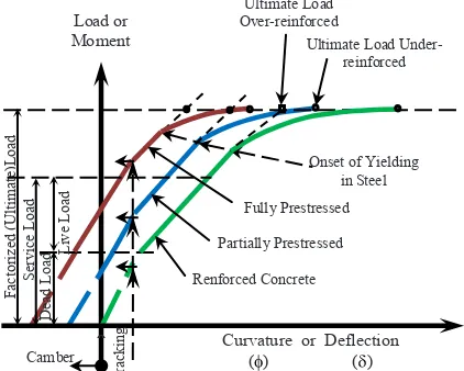
According to Naaman (1982), in a combination of partially prestressed and non-prestressed reinforcements, both reinforcements contribute to the resistance of the structure. The advantage is to have a better control of camber and deflection, and to increase ductility.
Figure 1. Typical of load-deflection relationship curva concrete structures (Naaman 1982)
2.2. Flexural Analysis of Partial Prestressed Concrete Beams
Partial prestressing ratio (PPR) according to Naaman (1982) is a parameter that indicates the level of concrete beams which partially prestressed. It is an expression of the ratio of ultimate moment contributed by prestressed steel and total ultimate moment provided by total tensile reinforcements. Value of PPR is in the range of 0 to 1, where value of 0 and 1 means the section is a reinforced concrete and a full prestressed concrete, respectively. Formulation of PPR can be expressed as follows (see Figure 2):
Ultimate Load
PPR =MMnp
n =
Aps .fff (dps p a2)
Aps . fffps dp 2 + Aa s. fff (dy s 2)a
(1)
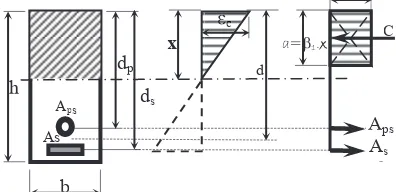
in which dp, ds and d is a distance from the top extreme fiber of the section to center fiber of prestressed force, non-prestressed tensile force and total tensile forces, respectively. In the case dp, ds and d are all equal value, then Equation (1) becomes:
The value d on condition of nominal moment resistance is:
Substitution of Equation (2) into Equation (3) yields:
where fffps is tensile stress in the prestressed steel at nominal moment resistance; fff isy
yield stress of non-prestressed steel; Aps is area of prestressed steel section and As is
area of tensile steel section.
Figure 2. Block diagram of compressive stress in partial prestressed concrete (Miswandi 1999)
2.3. Ductility of prestressed concrete section
2.3.1 The state of the first yielding
In prestressed concrete, the steel is already subjected to an initial prestressing force before loading. Hence, an initial strainii exists in the prestressing steel. With the existence of initial strain Spo, the total strain in the prestressing steel sp can be
expressed as follows (Figure 3) :
In a state of spy and its value together with Spo and 1 spare as follows:
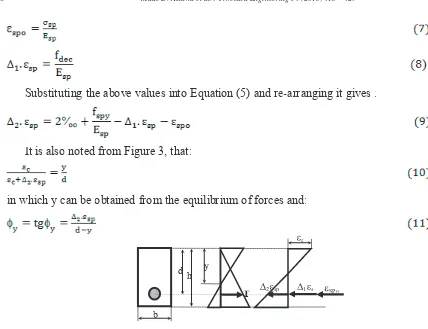
Substituting the above values into Equation (5) and re-arranging it gives :
It is also noted from Figure 3, that:
in which y can be obtained from the equilibrium of forces and:
Figure 3. Block diagram illustrating strains and forces in the presstressed concrete section (Raka 1993)
2.3.2 Ultimate conditions
Figure 4. Block diagram illustrating strains and forces in presstressed concrete section at ultimate condition (Raka 1993)
Using block diagram as illustrated in Figure 4, it is obtained identical terms with reinforced concrete:
and:
in which yyy can be obtained from the principle of forces equilibrium. If we defineu
and then substitute Equation (12) into (13), we obtain:
SNI 03-2847-2002 section 20.7.4 specifie cu is . Meanwhile, 2. sp
can be obtained from Equation (10) by first, calculating the value of y. Similarly, 3. sp
can be obtained from Equation (12) by first calculating yyy . The term u sp is acquired
from the value of 3. spwhere this value is determined from the equilibrium of forces at
ultimate state.
2.4. Factors affecting the ductility
2.4.1 The number of prestressed steel
In order for flexural strength of prestressed concrete having ductility that meets the requirements, then the amount of prestressing steel used should be in proportion to the required flexural strength to bear the gravity loads. ACI 318-77 and UBC-97 give the limits of the use of prestressing steel in order to assure the condition of under-reinforced as follows :
When pp> 0.3 there will be an increase in flexural strength but a lower ductility and
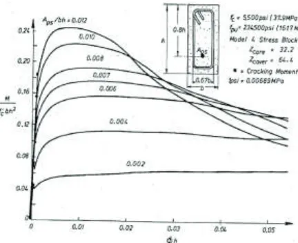
Figure 5. The influence of the prestressing steel moment and curvature relationship in prestressed concrete beams with 1 (one) layer of prestressing tendons (Park & Thompson, 1980)
If the area of prestressing steel is within the limit of that required in Equation (15) the brittle collapse will be avoided. However, in the case of earthquake load where the curvature is preferred to be maintain at a large ductility, the use of prestressing steel should be limited further. So, the limit of pp 0,3 is replaced by pp 0.2. If cross section
is determined such that resulting in a value of , according to Figure 5 the section should have a better ductility, and for earthquake-resistant design it is recommended to change Equation (15) becomes on the beam plastic joints, when all prestressed tendons concentrated close to the extreme fiber. The average of the prestressed force must 0,2.fff .b.d, and when concrete compressive force is 0.85.c
fc
ff the maximum height of the concrete compressive stress block are: . If d = 0.8h and a = 0.75c then:
a 0,2h or c 0,25h (16)
According to SNI 03-2847-2002 article 20.8.1, a limit of reinforcements is:
where:
p= index of prestressed steel
= index of tensile reinforcing steel of non-prestressed
' = index of compressive reinforcing steel of non-prestressed f'c= concrete cylinder compressive strength characteristics
b = width of concrete
d = distance of the center point of the tensile steel reinforcement to the top extreme fiber of the section
2.4.2 Transverse reinforcement (stirrups)
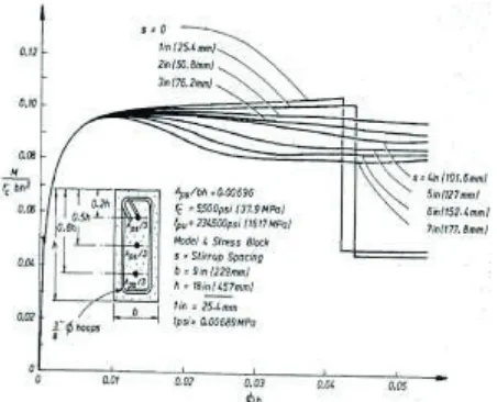
Studies of the effect of confinement degree on the level of ductility of partially prestressed concrete (Miswandi in K. Gideon & Andriono. T 1994) can be performed using Monte Carlo techniques to obtain the magnitude of curvature ductility ( u/ y) of each beam section modeled in each frame structure.
Figure 6 shows the relationship between ductility curves and the curvature of the cross-sectional moment of 3 layers of prestressing tendons distributed symmetrically with the variation of the spacing of reinforcing cross bar; with bar diameter of 3/8"(9.5 mm) and variation between cross bar spacing s = 1" to 7 "(25.4 mm to 178 mm) with thickness of concrete cover 1.5".
2.5. Beam Column-Joint
2.5.1 The minimum flexural strength column
SNI 03-2847-2002 sets a minimum column flexural strength for structural components that received a combination of bending and axial load on SRPMK. The flexural strength of columns determined according to section 23.4.2, must meet the following requirements:
where:
Me= total moment of columns at the beam-column connection.
Mg= total moment of beams at the beam-column connection. 2.5.2 Longitudinal reinforcement and stirrups of column
According to SNI 03-2847-2002 section 23.4.3, the minimum number of longitudinal column reinforcement shall meet the following requirements:
(1) Reinforcement ratio of 0,01 g 0,06
(2) Mechanical connection must be 125% yield stress of elements to be joined. Fanella David. A and Munshi Javeed. A (1988) with reference to the UBC-1997 suggested to extend the column reinforcement connection up to the mid-height of the column regardless the location of high pressure.
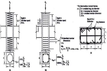
Transverse reinforcement is placed along the height of the column, according to SNI 03-2847-2002 provisions of article 23.4.4 as follows:
(1) Minimum volumetric ratio of spiral reinforcement or stirrups ring, s should fit the
following equation :
and should not be less than:
(2) The total area covered with a square cross-section of cross bar must meet the following minimum requirements :
Column at which point of contraflexure are not in a clear half-height, transverse reinforcement as required in UBC section 1921.4.4.1 shall be given over the full height of the elements. This is also in line with Nawy E.G (2005).
Figure 7. Typical reinforcement details of column confinement: (a) the spiral confinement (b) Confinement with rectangular cross bar, (c) Detail of cross-section of cross bar tie, x 14 inch. Transverse row of the tie should have a hook 90° bend on the opposite side (Fanella David A and Munshi
Javeed. A, 1998)
3. Methode
3.1.Proposed design and fabrication of specimens
Specimens of Exterior Beam-Column joint have the following specifications :
Design and manufacture of precast beam
Sectional dimension of the beam is 250/400 mm, with concrete cover of 35 mm. The main reinforcements are as follows: in tensile area is 5D13; in the compression area is
3D13; the transverse reinforcement (stirrups) is 8-75 mm. The position of the pedestal
for prestressing tendons at the joint is on the top side of the beam section, forming a parabolic curve until reaching the center of the beam at its end.
Design and manufacture of Precast Columns
The main reinforcement are 6 D16 + 4 D13 distributed evenly on the edge of the column
and enclosed with transverse reinforcement (stirrups) 10-50 mm.
Three specimens of the representative structures are shown in the following Table1.
Table1. Summary specifications of the specimens
Type of
The results of the specimen design
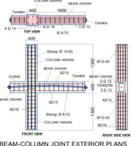
The design of exterior beam-column specimens connection is indicated in Figure 8.
Figure 8: Design of the Specimen of txterior beam-column joint
3.2.Plan of Loadings
2000 kN, and the capacity Actuatur Dynamik lateral load = 1000 kN. Loadings on the specimens must be less than load capacity in the laboratory instrument.
Design load capacity of beams
According ACI Code 318M-08,section 21.5.2.5 (c), the maximum capacity of prestressing tendons due to the support beam on the moment of lateral earthquake load is to be 25%
Actuator capacity = 1000 kN, taking effective value of 80%: = 0.8 (1000) = 800 kN.
In the design of structural load capacity, the specimen is assumed in elastic state, so the structure has not been cracked.
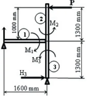
Figure 9: Moment distribution in the specimen
Actuator moment due to lateral force P is 800 kN. 1 m = 800 KNM, becomes the primary moment.
Stiffness of elements:
and moment distribution factors:
M1 = 0.24 (800) = 192 KNM; M2 = M3 = 0.38 (800) = 304 KNM
Mn1 reinforcement = 82.12 KNM
Mn of prestressing tendons:
X = a/ 1 = 82,4/0,77 = 107 mm ;
e = 282-107 = 175 mm
Mn2 = F (e) = 379 (175).10-3 = 66,33 kNm
Mn = Mn1+25 % (Mn2) = 82,12 + 0,25 (66,33)
= 98,70 kNm 192 kNm (Ok) Design Load Capacity of Columns
Equipment capacity is 2000 kN and taking effective capacity of 80% results in 0.8 (2000) kN = 1600 kN. Maximum capacity of the column with concrete compressive
strength is:
Pn = 0.25 fc '. Ag = 0.25. 40. (400)2 = 1280 kN 1280 kN <1600 kN ... (Ok).
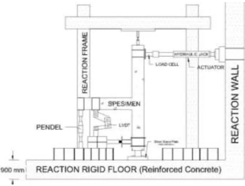
3.3.Test set-up
The pattern of loading is dynamic loading (pseudo dynamic) that resembles the actual earthquake load.
Figure 10: Model test set-up Specimens
Figure 11: Lateral Displacement time history pattern due to dynamic loads
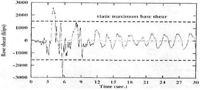
Similarly for the history of the time pattern of load-shear relationship is also not uniform as seen in Figure 12 below.
Figure 12: Historical Shear Patterns of time due to Dynamic load
3.4. Expected test results
a. Capacity: Pideal<Pyielding test results, where
Py/Pi = fi, (fi according to SNI 03-1726-2002 = 1.6), fi = 1.2 is the minimum requirement.
b. Ductility, = ( max/ first yielding), in which can be calculated up to the boundary
condition of the stable structure.
c. Seismic reduction factor R is taken from SNI 03-1726-2002.
4. Conclusions
Interpretation of the results of analysis of research data will form the basis to formulate conclusions. Several conclusions can be drawn from the analysis of data about the behavior of the specimen which includes:
a. dynamic load characteristics and the monotonic behavior b. specimens in the load carrying capacity,
c. ductility,
d. stiffness degradation, e. deterioration of strength,
f. drift / displacement and ultimate shear
g. all aspects of the ease or difficulty encountered during the research process.
Acknowledgement
In writing and making this study design we were much aided by various parties, especially the promotor Prof. I.G.P. Raka, DEA and Tavio, Ph.D., the examiners: Prof. Priyo Suprobo. Dr. Bambang Supriyadi and Handayanu Ph.D. Our gratitude also goes to LPPM-ITS for assistance fund through outstanding ITS Research, Research of DITLITABMAS-decentralization program, National Development University "Veteran" East Java which has given me the opportunity to pursue doctorate study in ITS.
References
American Concrete Institut(ACI 318-77) , 1977
American Concrete Institut(ACI
318M-CamarenaD Finite elemen analysis of precast prestressed beam-column concrete conection in
Seismic C
devision of structural engineering concrete structures, chalmers university of technology, göteborg-sweden.
El-SheikhMagdyT, SauseRichard, PassikiStephen, Lu Le-Wu, May-J Seismic Behavior and
design of unbonded
post-Fanella David A, Munshi Javeed. A Design o
PortlandCementAssociation.
Ghosh S. K, May-J Impact of earthquake design provisions of International BuildingC
PCIJournal.
KashiwazakiTakashi, HoguchiH StructuralPerformances of prestressed concrete interior
beam- Proceedings of 12th word conference on earthquake engineering, paper no.
2342, auckland-New zealand, isbn : 0-9582154-0-5.
Kusuma Gideon, AndrionoT Desain struktur rangka beton bertulang didaerah rawan
Erlangga-Jakarta.
Lin T. Y, Burns ned. H, Indrawan D Desain struktur beton prategang Erlangga
Jakarta.
Miswandi V Eka,1999 Pengaruh nilai PPR dan tulangan transversal terhadap tingkat daktilitas balok
betonpratekan parsial pada struktur rangka penahan Tesis Magister Teknik Sipil ITS.
Surabaya.
MurahidyA. G, Carr A. J, Spieth H. A, Mander J. B & Bull D. K Design construction and dynamic testing of a post-tensioned precast reinforced concrete frame building with rocking beam-column
Conference.
Nakano K, Tanabe K, Machida S, & Wada S Damage controlled seismic design by
precast-prestressed concrete structure with mild-press- Basicconsept of design, AIJ Summeries
of Technical papers of Annual meeting, Japan.
Naaman Antoine .E P Mcgrow-Hill book company,
NewYork, San Francisco,Auckland, Bogota, Hamburg, Johannesburg, London, Madrid, atc.
Naaman Antoine E, SiriaksornA Analysis and design of partially prestressed to statisfy
Prestressed Concrete Institute and by the University of Illionis, Chicago.
Naaman Antoine E, Nop-D Partially
special report, PCI. Journal.
NawyEdward G P Pearson Prentice Hall, Upper Saddle River, NewJersey
07458.
Nawy Edward G Reinforced C (a fundamental approach), Pearson Prentice Hall, Upper
Saddle River, NewJersey 07458.
Nilson Arthur H D John Wiley & Sons, inc, NewYork, Chichester,
Brisbane, Toronto, Singapore.
Park R and Paulay T R JohnWiley & Sons, NewYork, Chichester,
Brisbane, Toronto, Singapore.
Paulay T, Priestley M. J. N Seismic design of reinforced concrete and masonry
JohnWiley&Sons, NewYork, Chichester, Bbrisbane, Toronto, Singapore.
Raka I Gusti P C precontraintes par
Desertasi D Institut National des
Sciences Appliquees de Toulouse Prancis.
Raka I Gusti P Duktilitas penampang tiangpancang pratekanbulat berongga hasil pemadatan
Laporan Penelitian, JurusanTeknik Sipil-FTSP ITS Surabaya.
SNI 03-2847- Tata cara perhitungan struktur beton untuk bangunan Laboratorium Beton
ITS Surabaya.
SNI 03-1726- Struktur gedung tahan Badan Standardisasi Nasional (BSN), Jakarta.
Thompson Kevin J, Park Robert, March-A Ductility of prestressed and partially prestressed
Uma S. R, MeherPrasad. A Seismic behavior of beam column joints in reinforced concrete moment