Approval Date: 2015-05-23 Publication Date: 2015-07-22
External identifier of this OGC® document: http://www.opengis.net/doc/BP/cdb-vol1/1.0 Internal reference number of this OGC® document: 15-003
Version: 1.0.0 Category: OGC® Best Practice Editor: David Graham
OGC Common DataBase
Volume 1 Main Body
Copyright notice
Copyright © 2015 Open Geospatial Consortium
To obtain additional rights of use, visit http://www.opengeospatial.org/legal/.
Warning
This document defines an OGC Best Practices on a particular technology or approach. This document is not an OGC Standard and may not be referred to as an OGC Standard. It is subject to change without notice. However, this document is an official position of the OGC membership on this particular technology topic.
distribute, and/or sublicense copies of the Intellectual Property, and to permit persons to whom the Intellectual Property is furnished to do so, provided that all copyright notices on the intellectual property are retained intact and that each person to whom the Intellectual Property is furnished agrees to the terms of this Agreement.
If you modify the Intellectual Property, all copies of the modified Intellectual Property must include, in addition to the above copyright notice, a notice that the Intellectual Property includes modifications that have not been approved or adopted by LICENSOR. THIS LICENSE IS A COPYRIGHT LICENSE ONLY, AND DOES NOT CONVEY ANY RIGHTS UNDER ANY PATENTS THAT MAY BE IN FORCE ANYWHERE IN THE WORLD.
THE INTELLECTUAL PROPERTY IS PROVIDED "AS IS", WITHOUT WARRANTY OF ANY KIND, EXPRESS OR IMPLIED, INCLUDING BUT NOT LIMITED TO THE WARRANTIES OF MERCHANTABILITY, FITNESS FOR A PARTICULAR PURPOSE, AND NONINFRINGEMENT OF THIRD PARTY RIGHTS. THE COPYRIGHT HOLDER OR HOLDERS INCLUDED IN THIS NOTICE DO NOT WARRANT THAT THE FUNCTIONS CONTAINED IN THE INTELLECTUAL PROPERTY WILL MEET YOUR REQUIREMENTS OR THAT THE OPERATION OF THE INTELLECTUAL PROPERTY WILL BE
UNINTERRUPTED OR ERROR FREE. ANY USE OF THE INTELLECTUAL PROPERTY SHALL BE MADE ENTIRELY AT THE USER’S OWN RISK. IN NO EVENT SHALL THE COPYRIGHT HOLDER OR ANY CONTRIBUTOR OF
conforms to this Specification is referred to as a Common DataBase or CDB. A CDB provides for a synthetic environment repository that is plug-and-play interoperable between database authoring workstations. Moreover, a CDB can be used as a common on-line (or runtime) repository from which various simulator client-devices can
simultaneously retrieve and modify, in real-time, relevant information to perform their respective runtime simulation tasks; in this case, a CDB is plug-and-play interoperable between CDB-compliant simulators. A CDB can be readily used by existing simulation client-devices (legacy Image Generators, Radar simulator, Computer Generated Forces, etc.) through a data publishing process that is performed on-demand in real-time. The application of CDB to future simulator architectures will significantly reduce runtime-source level and algorithmic correlation errors, while reducing development, update and configuration management timelines. With the addition of the HLA/FOM and DIS protocols, the application of the CDB Specification provides a Common
Environment to which inter-connected simulators share a common view of the simulated environment.
The CDB Specification is an open format Specification for the storage, access and modification of a synthetic environment database. The Specification defines the data representation, organization and storage structure of a worldwide synthetic representation of the earth as well as the conventions necessary to support all of the subsystems of a full-mission simulator. The Specification makes use of several commercial and simulation data formats endorsed by leaders of the database tools industry.
The CDB synthetic environment is a representation of the natural environment including external features such as man-made structures and systems. It encompasses the terrain relief, terrain imagery, three-dimensional (3D) models of natural and man-made cultural features, 3D models of dynamic vehicles, the ocean surface, and the ocean bottom, including features (both natural and man-made) on the ocean floor. In addition, the synthetic environment includes the specific attributes of the synthetic environment data as well as their relationships.
A CDB contains datasets organized in layers, tiles and levels-of-detail; together, these datasets represent the features of a synthetic environment for the purposes of distributed simulation applications. The organization of the synthetic environmental data in a CDB is specifically tailored for real-time applications.
ii.
Keywords
At the suggestion of several attendees at the first CDB ad-hoc meeting in September, 2014, the current version of the existing CDB specification has been slightly reformatted for publication as an OGC Best Practice.
Attention is drawn to the possibility that some of the elements of this document may be the subject of patent rights. The Open Geospatial Consortium shall not be held
responsible for identifying any or all such patent rights.
Recipients of this document are requested to submit, with their comments, notification of any relevant patent claims or other intellectual property rights of which they may be aware that might be infringed by any implementation of the standard set forth in this document, and to provide supporting documentation.
iv.
Submitting organizations
The following organizations submitted this Document to the Open Geospatial Consortium (OGC):
CAE Inc.
v.
Submitters
All questions regarding this submission should be directed to the editor or the submitters:
Name Affiliation
David Graham CAE Inc.
addresses the interoperability challenge of full plug-and-play interoperability and re-use of synthetic environment databases used for high fidelity simulation and mission
rehearsal.
The first CDB specification was developed under a competitive contract awarded to CAE to meet requirements of the United States Special Operations Command. The CDB Specification was required to be open and non-proprietary as part of the original
requirements. The revision history of the industry-maintained specification is contained in the following document sections.
The CDB specification was been widely implemented by multiple, independent industry contractors for end-user simulation and mission rehearsal customers in many different countries over a period of ten years.
For ease of editing and review, the specification has been separated into two Volumes. Volume 1 contains the main body of the specification, and Volume 2 contains the appendices. Nevertheless, the documents remain large and verbose, as the current, industry maintained specification has functioned as a data model, an encoding
specification, and an engineering tutorial on how to implement this new and different simulation synthetic environment paradigm.
Revision History
The new revision history is presented in reversed chronological order where the most recent revision appears at the top of the table.
Version Date Description
3.2 19 March 2014 Changes:
- Updated the list of DIS codes found in /CDB/Metadata/Moving_Model_Codes.xml
- Editorial changes to volume 1 and 2 to remove markups and highlights, promote a consistent use of various terms and expressions, check spelling, correct the formatting, etc. 12 February 2014 First public release of version 3.2 of the CDB Specification.
The changes with respect to the first release candidate of 19 December 2013 are the followings:
- Revised the implementation of the Primary Alternate Elevation (formely Subordinate Terrain Offset) - Added the Subordinate Alternate Bathymetry
- Introduced the concept of Mesh Type and added an optional channel to the Primary Terrain Elevation and Subordinate Bathymetry components to store the Mesh Type.
19 December 2013 First release candidate of version 3.2 of the CDB Specification.
The changes with respect to the first draft of December 2012 take into account comments received from users and address concerns about compatibility with version 3.0.
December 2012 First Draft of version 3.2 of the CDB Specification.
Old Revision History
The old revision history is presented in chronological order where the most recent revision appears at the bottom of the table.
Revision Level Date Description
V1.0 – First Draft October 28, 2005 First draft available for comments from industry
V2.1 – Third Draft October 25, 2006 Third draft of the CDB Specification V2.2 – Fourth Draft June 15, 2007 Fourth draft of the CDB Specification V2.3 – Fifth Draft July 9, 2007 Fifth draft of the CDB Specification V2.4 – Sixth Draft October 5, 2007 Sixth draft of the CDB Specification V2.5 – Seventh Draft November 9, 2007 Seventh draft of the CDB Specification V3.0 – Draft December 21, 2007 First draft of CDB 3.0
V3.0 – Draft 2 March 27, 2008 Second draft of CDB 3.0 V3.0 – Draft 3 June 25, 2008 Third draft of CDB 3.0 V3.0 September 2008 Official release of CDB 3.0 V3.1 – Draft November 2009 First draft of CDB 3.1
V3.1 May 2010 Official Release of CDB 3.1
Table of Contents
1 Introduction ... 1
1.1 Purpose ... 1
1.2 Document Structure ... 1
1.3 Scope ... 2
1.3.1 What is the CDB Specification ... 3
1.3.1.1 Use of CDB as an Off-line Database Repository ... 5
1.3.1.2 Use of CDB as a Combined Off-line and Run-time Database Repository ... 9
1.3.2 What the CDB Specification Is Not ... 12
1.3.3 What is a CDB ... 13
1.4 Key Features and Characteristics of the CDB Specification ... 14
1.4.1 Synthetic environment Database for Simulation Applications ... 14
1.4.2 Logical Addressability ... 14
1.4.3 High Spatial Resolution and Scalability ... 14
1.4.4 Earth Geodetic Spatial Representation Model ... 15
1.4.5 Tile/Layer/Level-of-Detail Structure ... 15
1.4.5.1 Tiles ... 15
1.4.5.2 Layers ... 15
1.4.5.3 Levels-of-Detail ... 16
1.4.6 Platform Independence ... 16
1.4.6.1 System Software Independence ... 17
1.4.6.2 System Hardware Independence ... 18
1.4.7 Synthetic Environment Scalability & Adaptability ... 21
1.4.8 Platform Scalability ... 23
1.4.9 Simulator Wide Unique Data Representation, Data Normalization ... 25
1.4.11 Compression of other Raster Datasets ... 27
1.5 Key Benefits of the CDB Specification ... 27
1.5.1 Improved Synthetic environment DB Generation Timeline ... 27
1.5.2 Interoperable Simulation-Ready Synthetic environment DB ... 28
1.5.3 Improved Client-device Robustness/Determinism ... 28
1.5.4 Runtime-Adjustable Synthetic Environment DB Correlation and Fidelity ... 29
1.5.5 Increased Synthetic Environment DB Longevity ... 29
1.5.6 Reduced Synthetic Environment DB Storage Infrastructure Cost ... 30
1.6 CDB Primer ... 30
1.6.1 CDB Specification Data Representation and Organization ... 31
1.6.2 CDB Specification Logical Structure ... 32
1.6.3 CDB Structure, Organization on Media and Conventions ... 33
1.6.4 Typical Implementation on a Simulator ... 34
1.6.4.1 Database Generation Facility ... 35
1.6.4.2 Database Generation Flow ... 36
1.6.4.3 Update Manager ... 39
1.6.4.4 CDB Servers ... 40
1.6.4.5 Other Applications of the CDB Specification ... 44
1.6.5 Use of CDB in Applications Requiring Dynamic Synthetic Environments ... 44
1.6.6 Synthetic Environment Database Correlation ... 45
2 CDB Concepts ... 55
2.1 Partitioning the Earth into Tiles ... 55
2.1.1 Description ... 56
2.1.2 Tile Levels-of-Detail (Tile-LODs) ... 59
2.1.2.1 Tile-LOD Area Coverage Rules ... 63
2.1.2.2 Tile-LOD Hierarchy Rules ... 64
2.1.3 Handling of the North and South Pole ... 64
2.2 File System Requirements ... 65
2.2.1 Character Set ... 65
2.2.2 A word about case-sensitiveness ... 66
2.3 Light Naming ... 67
2.3.1 Adding Names to the CDB Light Name Hierarchy ... 69
2.4 Model Component Naming ... 69
2.4.1 Adding New Model Components ... 70
2.5 Materials ... 70
2.5.1 Base Materials ... 71
2.5.1.1 Base Material Table (BMT) ... 71
2.5.2 Composite Materials ... 71
2.5.2.1 Composite Material Substrates ... 72
2.5.2.2 Composite Material Tables (CMT) ... 74
2.5.2.3 Example 1 ... 76
2.5.2.4 Example 2 ... 76
2.5.3 Bringing it all Together ... 76
2.5.4 Determination of Material Properties by SEM ... 77
2.5.4.1 Example ... 78
2.5.5 Generation of Materials for Inclusion in CDB Datasets ... 79
3 CDB Structure ... 81
3.1 Top-Level CDB Structure Description ... 81
3.1.1 Metadata Directory ... 82
3.1.2 Metadata File Examples ... 84
3.2 CDB Configuration Management ... 84
3.2.1.1 CDB Extensions ... 86
3.2.2 CDB Version Directory Structure ... 86
3.2.3 CDB File Replacement Mechanism ... 87
3.2.3.1 How to Handle Archives ... 89
3.2.3.2 How to Handle the Metadata Directory ... 89
3.2.4 CDB Configuration ... 89
3.2.5 Management of CDB Configurations and Versions ... 90
3.3 CDB Model Types ... 91
3.3.1 GTModel (Geotypical 3D Model) ... 92
3.3.2 GSModel (Geospecific 3D Model) ... 92
3.3.3 T2DModel (Tiled 2D Model) ... 92
3.3.4 MModel (Moving 3D Model) ... 92
3.3.5 Use of GSModels and GTModels ... 93
3.3.6 Organizing Models into Levels of Details ... 96
3.3.7 Organizing Models into Datasets ... 98
3.3.8 Terms and Expressions ... 99
3.3.8.1 Feature Classification ... 99
3.3.8.2 Model Name ... 99
3.3.8.3 DIS Entity Type ... 99
3.3.8.4 Texture Name ... 100
3.3.8.5 Level of Detail ... 101
3.4 GTModel Library Datasets ... 101
3.4.1 GTModel Directory Structure 1: Geometry and Descriptor ... 101
3.4.1.1 GTModelGeometry Entry File Naming Convention ... 102
3.4.1.2 GTModelGeometry Level of Detail Naming Convention ... 103
3.4.1.3 GTModelDescriptor Naming Convention ... 104
3.4.1.4 Examples ... 104
3.4.2.1 GTModelTexture Naming Convention ... 106
3.4.2.2 GTModelMaterial Naming Convention ... 106
3.4.2.3 GTModelCMT Naming Convention ... 107
3.4.2.4 Examples ... 107
3.4.3 GTModel Directory Structure 3: Interior Geometry and Descriptor ... 108
3.4.3.1 GTModelInteriorGeometry Naming Convention ... 109
3.4.3.2 GTModelInteriorDescriptor Naming Convention ... 110
3.4.3.3 Examples ... 110
3.4.4 GTModel Directory Structure 4: Interior Texture, Material, and CMT ... 111
3.4.4.1 GTModelInteriorTexture Naming Convention ... 112
3.4.4.2 GTModelInteriorMaterial Naming Convention ... 113
3.4.4.3 Example 1 ... 113
3.4.4.4 Example 2 ... 114
3.4.5 GTModel Directory Structure 5: Signature ... 114
3.4.5.1 Naming Convention ... 115
3.4.5.2 Examples ... 116
3.4.6 GTModel Complete Examples ... 116
3.5 MModel Library Datasets ... 117
3.5.1 MModel Directory Structure 1: Geometry and Descriptor ... 117
3.5.1.1 MModelGeometry Naming Convention ... 118
3.5.1.2 MModelDescriptor Naming Convention ... 119
3.5.1.3 Examples ... 119
3.5.2 MModel Directory Structure 2: Texture, Material, and CMT ... 120
3.5.2.1 MModelTexture Naming Convention ... 120
3.5.2.2 MModelMaterial Naming Convention ... 121
3.5.2.3 MModelCMT Naming Convention ... 121
3.5.2.4 Examples ... 122
3.5.3 MModel Directory Structure 3: Signature ... 122
3.5.3.1 Naming Convention ... 123
3.5.3.2 Examples ... 124
3.6 CDB Tiled Datasets ... 125
3.6.1 Tiled Dataset Types ... 125
3.6.1.1 Raster Datasets ... 125
3.6.1.2 Vector Datasets ... 126
3.6.1.3 Model Datasets ... 127
3.6.2 Tiled Dataset Directory Structure ... 127
3.6.2.1 Directory Level 1 (Latitude Directory) ... 129
3.6.2.2 Directory Level 2 (Longitude Directory) ... 130
3.6.2.3 Directory Level 3 (Dataset Directory) ... 132
3.6.2.4 Directory Level 4 (LOD Directory) ... 133
3.6.2.5 Directory Level 5 (UREF Directory) ... 133
3.6.3 Tiled Dataset File Naming Conventions ... 135
3.6.3.1 File Naming Convention for Files in Leaf Directories (UREF Directory) ... 135
3.6.3.2 File Naming Convention for Files in ZIP Archives ... 137
3.7 Navigation Library Dataset ... 139
3.7.1 NavData Structure ... 139
3.7.2 Naming Convention ... 139
3.7.2.1 Examples ... 139
4 CDB File Formats ... 141
5 CDB Datasets ... 145
5.1 Metadata Datasets ... 145
5.1.1 Light Name Hierarchy Metadata ... 146
5.1.1.1 Client Specific Lights Definition Metadata ... 147
5.1.2 Model Components Definition Metadata ... 150
5.1.3 Base Material Table ... 150
5.1.4 Default Values Definition Metadata ... 151
5.1.5 Specification Version Metadata – Deprecated ... 151
5.1.7 CDB Attributes Metadata ... 152
5.1.7.1 Definition of the <Attribute> Element ... 153
5.1.7.2 Definition of the <Unit> Element ... 154
5.1.7.3 Definition of the <Scaler> Element ... 154
5.1.7.4 Example of CDB_Attributes.xml ... 155
5.1.8 Geomatics Attributes Metadata ... 155
5.1.9 Vendor Attributes Metadata ... 155
5.1.10 Configuration Metadata ... 155
5.1.10.1 A Note about Folder Path ... 156
5.1.10.2 Example ... 156
5.2 Navigation Library Datasets ... 157
5.2.1 Schema Files ... 161
5.2.1.1 Example ... 162
5.2.2 Key Datasets ... 163
5.2.2.1 Example ... 164
5.3 CDB Model Textures ... 165
5.4 GTModel Library Datasets ... 167
5.5 MModel Library Datasets ... 169
5.6 Tiled Raster Datasets ... 171
5.6.1 Tiled Elevation Dataset ... 176
5.6.1.1 Terrain Mesh Types ... 177
5.6.1.2 List of all Elevation Dataset Components ... 178
5.6.1.3 Primary Terrain Elevation Component ... 179
5.6.1.4 Primary Alternate Terrain Elevation Component ... 182
5.6.1.5 Terrain Constraints ... 185
5.6.1.6 MinElevation and MaxElevation Components ... 188
5.6.1.7 MaxCulture Component ... 197
5.6.1.8 Subordinate Bathymetry Component ... 200
5.6.1.10 Subordinate Tide Component ... 204
5.6.2 Tiled Imagery Dataset ... 208
5.6.2.1 Raster-Based Imagery File Storage Extension Naming ... 208
5.6.2.2 List of all Imagery Dataset Components ... 215
5.6.2.3 Visible Spectrum Terrain Imagery (VSTI) Components ... 216
5.6.2.4 Visible Spectrum Terrain Light Map (VSTLM) Component ... 219
5.6.3 Tiled Raster Material Dataset ... 220
5.6.3.1 List of all Raster Material Dataset Components ... 223
5.6.3.2 Composite Material Index Component ... 223
5.6.3.3 Composite Material Mixture Component ... 224
5.6.3.4 Composite Material Table Component ... 225
5.7 Tiled Vector Datasets ... 226
5.7.1 Introduction to Vector Datasets ... 226
5.7.1.1 Shapefile Type Usage and Conventions ... 229
5.7.1.2 CDB Attribution ... 231
5.7.1.3 CDB Attributes ... 239
5.7.1.4 Explicitly Modeled Representations ... 287
5.7.1.5 Implicitly Modeled Representations ... 288
5.7.1.6 Handling of Topological Networks ... 288
5.7.1.7 Handling of Light Points ... 291
5.7.1.8 Allocation of CDB Attributes To Vector Datasets ... 291
5.7.2 Tiled Navigation Dataset ... 295
5.7.2.1 Default Read Value ... 295
5.7.2.2 Default Write Value ... 295
5.7.3 Tiled GSFeature Dataset ... 295
5.7.3.1 Default Read Value ... 297
5.7.3.2 Default Write Value ... 297
5.7.4 Tiled GTFeature Dataset ... 297
5.7.4.1 Default Read Value ... 298
5.7.4.2 Default Write Value ... 298
5.7.5.1 Boundary and Location Features ... 299
5.7.5.2 Elevation Constraint Features ... 301
5.7.5.3 Default Read Value ... 302
5.7.5.4 Default Write Value ... 302
5.7.6 Tiled RoadNetwork Dataset ... 302
5.7.6.1 Default Read Value ... 303
5.7.6.2 Default Write Value ... 303
5.7.7 Tiled RailRoadNetwork Dataset ... 304
5.7.7.1 Default Read Value ... 304
5.7.7.2 Default Write Value ... 304
5.7.8 Tiled PowerLineNetwork Dataset ... 305
5.7.8.1 Default Read Value ... 306
5.7.8.2 Default Write Value ... 306
5.7.9 Tiled HydrographyNetwork Dataset ... 306
5.7.9.1 Default Read Value ... 307
5.7.9.2 Default Write Value ... 307
5.7.10 Tiled Vector Composite Material Table (VCMT) ... 307
5.7.10.1 Data Type ... 307
5.7.10.2 Default Read Value ... 307
5.7.10.3 Default Write Value ... 308
5.8 Tiled Model Datasets ... 308
5.8.1 Tiled GSModel Datasets ... 308
5.8.2 Tiled T2DModel Datasets ... 309
6 CDB OpenFlight Models ... 311
6.1 OpenFlight File Header ... 311
6.2 OpenFlight Model Tree Structure ... 311
6.2.1 CDB Model Tree Structure ... 313
6.2.2 T2DModel Tree Structure ... 313
6.2.2.2 Node Attributes ... 315
6.2.3 The Use of Node Names ... 315
6.2.4 Model Master File ... 316
6.2.5 Referencing Other OpenFlight Files ... 317
6.2.5.1 Models Straddling Multiple Files ... 317
6.2.5.2 Models with Multiple Model-LODs ... 318
6.3 Modeling Conventions ... 318
6.3.1 Model Coordinate Systems ... 318
6.3.1.1 Origin ... 319
6.3.1.2 Local Coordinate Systems ... 323
6.3.1.3 Units ... 323
6.3.1.4 Roll, Pitch, Yaw ... 324
6.3.2 Geometry ... 324
6.3.3 Roof Tagging ... 325
6.3.4 Relative Priority ... 325
6.4 Model Identifiers ... 326
6.4.1 GSModel and GTModel Identifier ... 326
6.4.2 MModel Identifier ... 326
6.4.3 2DModel Identifier ... 326
6.5 Model Zones ... 327
6.5.1 Definition ... 327
6.5.2 Global Zones ... 328
6.5.3 Zone Attributes ... 328
6.5.3.1 Material ... 328
6.5.3.2 Temperature ... 329
6.5.4 Implementation Guidelines ... 330
6.5.6 Usages ... 334
6.5.6.1 Model Landing Zones ... 334
6.5.6.2 Model Footprint Zones ... 334
6.5.6.3 Model Cutout Zones ... 335
6.5.6.4 Model Interior Zones ... 337
6.6 Model Points ... 348
6.6.1 Definition ... 349
6.6.2 Usages ... 349
6.6.2.1 Model DIS Origin ... 349
6.6.2.2 Model Viewpoint ... 352
6.6.2.3 Model Attach Point ... 353
6.6.2.4 Model Anchor Point ... 353
6.6.2.5 Model Center of Mass ... 353
6.7 Model Conforming ... 354
6.7.1 Non Conformal (Absolute) Mode ... 355
6.7.2 Point Conformal Mode ... 355
6.7.3 Vertex Conformal Mode ... 356
6.7.4 Line Conformal Mode ... 357
6.7.5 Plane Conformal Mode ... 358
6.7.6 Surface Conformal Mode ... 360
6.8 Model Levels-of-Detail ... 361
6.8.1 Exchange LODs ... 363
6.8.2 Additive LODs ... 363
6.8.3 Significant Size ... 364
6.8.3.1 Significant Size – Coarsest LOD ... 364
6.8.3.2 Significant Size – Other LODs ... 366
6.8.4 LOD Node Ordering ... 367
6.9 Model Switch Nodes ... 369
6.9.1 Definition ... 369
6.9.2 Usage ... 370
6.9.2.1 Articulations ... 370
6.9.2.2 Damage States ... 370
6.9.2.3 Temporal Anti-aliasing ... 373
6.10 Model Articulations ... 375
6.10.1 Definition ... 375
6.10.2 Usage ... 376
6.10.2.1 Rotating Parts ... 376
6.11 Model Light Points ... 376
6.12 Model Attributes ... 378
6.12.1 Definition ... 378
6.12.2 Vendor Attributes ... 379
6.12.3 Examples ... 379
6.13 Model Textures ... 380
6.13.1 Handling of Multi-textures ... 380
6.13.1.1 Base Texture Layer ... 380
6.13.1.2 Subordinate Texture Layer ... 381
6.13.1.3 Texture Mapping Conventions ... 382
6.13.2 Default Gamma Corrections ... 383
6.13.3 Texture Dimension ... 383
6.13.3.1 Texture Mipmap ... 383
6.13.3.2 Texture Size ... 384
6.13.3.3 Texel Size ... 384
6.13.4 Texture Palette ... 384
6.13.4.1 MModel Example ... 384
List of Figures
List of Tables
Preface
Intended Audience
The primary audience for this document includes distributed simulation system developers and synthetic environment database tool developers whose applications are intended to read and/or write synthetic environment database files. To this end, this document discusses concepts incorporated in the Specification and contains a detailed description of the physical layout of the files as represented on disk.
This document assumes the reader is familiar with:
(1) Synthetic environment creation and generation process.
(2) Existing database interchange and database visualization standards (such as SEDRIS, SIF, OpenFlight, DIS, DIGEST, Shapefile, TIFF, JPEG, etc.).
(3) Image Generation and radar simulation principles.
(4) Sensor subsystems used in aircraft and other vehicles (Radar, Night Vision Image Intensifiers, Infrared (IR) sensors, Laser Range Finders, etc.) requiring the use of synthetic environment databases.
(5) Simulator client-devices (such as Computer Generated Forces, Air/Ground Traffic Control, Weather, etc.) requiring the use of synthetic environment databases.
(6) Principles of Object-Oriented (OO) programming.
Problem Definition
Complex mission simulators include a wide range of subsystems designed to simulate on-board equipment and to provide a rich gaming environment complete with weather, computer
generated forces, ordnance, air traffic, networked players, etc. Each of these subsystems typically utilizes a proprietary runtime database (and format) for its synthetic representation of the gaming area. Traditionally, these application-specific formats have been generated off-line at a database generation facility using a variety of tools and processes. This approach has several inherent disadvantages, including length of time needed for synthetic environment production for multiple simulation applications, loss of correlation due to compilation differences, complexity in configuration management, and an inefficient update process. The abundance of distinct database formats creates several challenges for configuration management, resulting in mismatched correlation of the various cues, and in the increased timeline needed to generate these databases. The CDB Specification is a new approach that establishes a set of industry-standard formats and conventions for all simulator client subsystems (aka simulator client-devices).
force simulation engineers to make important compromises between a subsystem’s targeted fidelity and its level of generality, scalability, abstraction, and correlation with other simulator client-devices. Industry wide standardization could not be readily achieved because
technologically viable options only offered partial solutions to these needs. Digital technologies have made tremendous strides in the past 10 years and are narrowing the “gap” between what is required for training and what the technology can now deliver. As this trend continues,
simulation engineers can re-examine all of these earlier trade-offs, and redress past compromises. The approach to visual system synthetic environments is rife with such compromises. For
instance, most DB formats in use today still require a full off-line re-compilation of the DB into a (usually proprietary) runtime format, even for a small-area update. As a result, the creation and update of such databases is still a recurring labor-intensive exercise. Separate, non-harmonized, Image Generator (IG) manufacturer proprietary tools are required to generate and modify the DB, resulting in sometimes incongruous, incomplete, and closed DB formats. The typical evolution of the DB format poses important configuration control challenges due to the required reconciliation of incompatible revisions of these DB formats. The entire process is further aggravated by the time-consuming off-line compilation of visual, sensor, threat, and air traffic DBs.
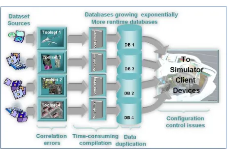
The confluence of digital multi-spectral high-resolution satellite imagery and highly capable visual systems has created dramatic new Mission Planning and Mission Rehearsal capabilities. As a result, recent environment databases built to take advantage of these new capabilities require orders of magnitude more storage than equivalent databases just a few years ago. It is clear that, if left unchecked, these factors will become important cost drivers and currently impact simulators (see Figure P-1: Current Approach to Synthetic Environment Generation) in the following areas:
(1) Size of the Synthetic Environment Storage:
In order to satisfy the runtime device loadable representation of each of the simulator client-devices, the synthetic environment is replicated several times. Most runtime device-loadable formats do not take advantage of modern
compression schemes. Furthermore, each of runtime device-loadable formats imposes its own distinct database structure; in many cases, the organization of the runtime database is not sufficiently flexible to permit small-area changes without a recompilation of the database. Each recompilation generates a complete copy of the database that must then be deployed and put under configuration control.
(2) Longevity of the Synthetic Environment Database:
simulator technology can be realized unless the runtime DB is rebuilt to the new simulator capabilities.
(3) Scalability of the Synthetic Environment Database:
The runtime loadable representation typically provided by current vendors for each of the simulator client-devices is closely aligned to the total content and density limits imposed by each simulator client-devices. Once “frozen” into the runtime loadable DB, it is difficult to fully take advantage of emerging simulator technologies capable of handling greater DB content/density. (4) Environment Database Correlation:
Correlation between simulator client-devices is aggravated due to the alternate data representations demanded by each of the (often proprietary) simulator client-devices. Data representations can vary in resolution, precision, and in fidelity. A solution to the correlation issue is costly because each of the runtime DBs must be re-compiled to the capabilities of the most limited simulator client-device.
(5) Database Availability Timeline:
The extensive off-line compilation process that produces the runtime databases is time-consuming; furthermore, this is aggravated because important amounts of data are replicated in each of the runtime device-specific databases. While a parallel processing approach could alleviate this, many of current database compilation tools are not capable of supporting this. The transfer of the replicated databases from the DB generation facility to the simulator(s) wastes additional time. Finally, small-area updates are time-consuming because of the monolithic structure of the client-device runtime DBs.
(6) Configuration management:
The configuration management of distinct simulator client-devices requires additional effort because the client-specific runtime DBs must each be re-derived and re-compiled from the raw source data. The evolution of the (often proprietary) runtime DB formats poses additional configuration control
Figure P-1: Current Approach to Synthetic Environment Generation
The CDB Specification addresses these and other shortcomings through a common database Specification. It is intended as a simulation Specification for use in producing a unified synthetic representation of the world. A database built to the CDB Specification is referred to as a
Common Database (CDB). A CDB is a single-copy data repository from which various
simulator client-devices are able to simultaneously retrieve, in real-time, relevant information to perform their respective runtime simulation tasks.
The CDB Specification enhances unity and correlation between various simulator level client-devices (e.g., Visual, Radar), while improving database maintainability. As a result, one of the main benefits of the CDB Specification is the elimination of several types of correlation errors attributable to alternate, sometimes conflicting data representations required by each the simulator client-devices. The Specification achieves this by allowing all simulator clients-devices to share, in runtime, a single repository of the synthetic environment information. In addition, a CDB can also be used as a master repository for the authoring tools; as a result CDB content can be interchanged between DB workstations. Finally, in the case where one or more of the client-devices are not compliant to this CDB Specification, it is possible to revert to the conventional compilation paradigm, (i.e., compile the CDB into one or more client-device loadable (usually proprietary) representations).
The CDB Specification internal data representation model is based on the native formats used by industry-standard toolsets. As a result, it eliminates the time-consuming off-line database
between off-line and on-line compilation processes because modern computer platforms can now accomplish most of the compilation process in real-time1.
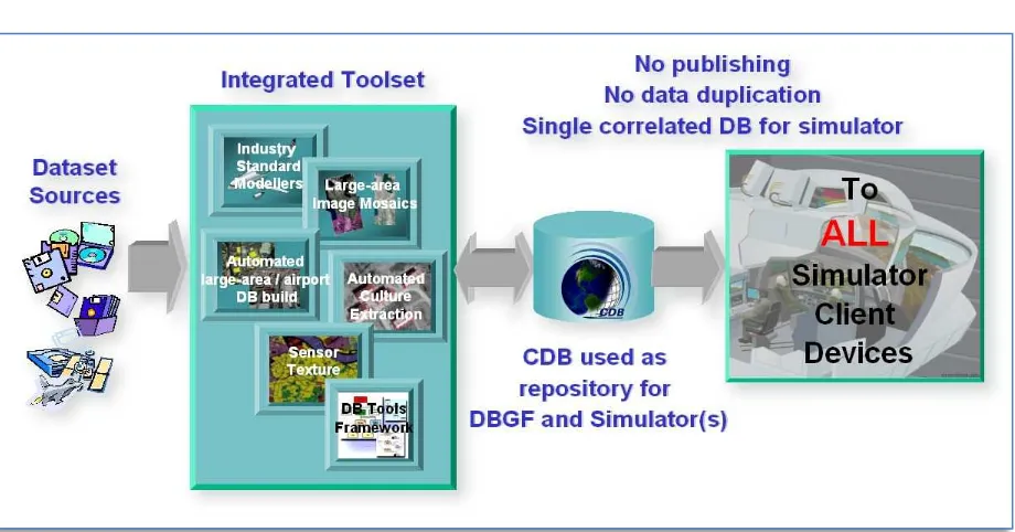
The CDB Specification addresses the issues that have characterized the simulation industry for past decades (see Figure P-2: CDB Approach to Synthetic Environment Generation), as follows:
(1) Size of Synthetic Environment Storage:
The CDB consolidates the synthetic environment into a single data repository that provides a static representation of the earth. It includes all the relevant information so that all the simulator client-devices can perform their
respective simulation tasks in order to meet the training and mission rehearsal requirements. It avoids any data content duplication. Storage intensive datasets can be optionally compressed using modern third-party algorithms. The CDB Specification provides a fine-grain versioning scheme that avoids the replication of the entire DB when effecting small-area updates.
(2) Scalability of Synthetic Environment Database:
A CDB can be built to a size or a density that far exceeds the capabilities of some or all of its client-devices. The data structure of the CDB Specification makes it possible to implement runtime filtering schemes to adjust the loaded CDB content density to the specific capabilities of the client-devices. As a result, a CDB can be scaled to take advantage of future simulator
technological improvements. (3) Environment DB Correlation:
Since CDB content is unique (without data duplication), runtime source level correlation errors among clients are eliminated, thereby ensuring
inter-subsystem coherence and simulator interoperability. In addition, it is possible to improve correlation by adjusting the runtime publishing process associated with each client-device.
(4) Database Availability Timeline:
The CDB generation process allows for small database incremental updates, thereby shortening generation and build process times. Furthermore, the translation step into CDB format is rather straightforward since the CDB Specification is based on industry-standard native tool formats.
(5) Configuration Management:
Configuration management effort is reduced, because a single CDB corresponds to the synthetic environment of all the client-devices in the simulator. Furthermore, while a CDB is conceptually a single, yet layered entity, the Specification internally supports incremental updates resulting in efficient storage and handling of CDB versions.
1
Chapter 1
1
Introduction
1.1 Purpose
This Specification provides a full description of a data model (aka schema) for the synthetic representation of the world. The representation of the synthetic environment in CDB format is intended for use by authoring tools and by various simulator client-devices that are able to simultaneously retrieve, in real-time, relevant information to perform their respective runtime simulation tasks. With the addition of the DIS protocol, the application of the CDB
Specification provides a Common Environment to which inter-connected simulators share a common view of the simulated environment.
1.2 Document Structure
A significant portion of the CDB Specification concerns itself with aspects of the data model that relate to the structure of the database repository on the storage subsystem. The organization of the CDB data into tiles, levels-of-detail and datasets is embodied through a set of conventions that prescribe the CDB directory hierarchy and file naming conventions. All aspects of the CDB structure are covered in Chapter 3.
A second important aspect of the CDB Specification deals with all of the naming conventions that are internal to the CDB. Names provide the simulator client-devices the necessary means to understand the meaning of and to control the various elements modeled within the synthetic environment. For example, the CDB naming conventions provide all the simulator client-devices the means to control cultural lighting, to articulate a landing gear on an aircraft, to animate a trailing wake on a ship, to control the heat emitted by a tank engine, to position a car on the ground, etc. Names also provide the means to attribute lights and to attribute materials. All of the CDB Concepts are stated in Chapter 2 that also deals with the naming and handling of materials that make up the synthetic environment.
Chapter 4, CDB File Formats provides a description of all the formats prescribed by the CDB Specification.
Chapter 5, CDB Datasets provides a detailed description of all CDB datasets.
For devices such as Radars, a geometric representation of a model may often provide a level of fidelity which is insufficient or inappropriate for use in simulation or alternately, it may not be feasible to compute a radar cross-section (RCS) of the model in real-time. Alternately, a user may wish to incorporate real-world RCS data into the simulator client-devices in order to further improve simulation fidelity. To this end, the CDB Specification defines a RCS (Radar Cross-Section) model representation for use by Sensor Simulation client-devices such as Radar and/or Sonar. Chapter 7, CDB Radar Cross Section (RCS) Models establishes a set of conventions that permit RCS representations using the Shapefile format.
The CDB Specification relies heavily on five established industry formats, namely the TIFF format (Appendix B), the OpenFlight format (Appendix C), the RGB format (Appendix P), the Shapefile format (Appendix D) and the JPEG 2000 file format (Appendix T). These
Specifications have been included as appendices to this Specification. Each of these documents has been annotated to reflect the conventions established by the CDB Specification. The
conventions define how TIFF, OpenFlight, RGB, Shapefile and JPEG 2000 formatted files are to be interpreted by CDB-compliant simulator readers.
Appendices E and F provide the CDB light type naming hierarchy and the CDB model component hierarchies respectively while Appendix L provides the material list for the CDB Specification.
Other Appendices further describes other aspects of the CDB Specifications like providing the CDB Directory Naming and Structure (Appendix M), the mapping of FACC Codes (Appendix N), the List of Texture Component Selectors (Appendix O), the SGI Image File Format
(Appendix P), the Table of Dataset Codes (Appendix Q) or how some datasets are derived from others (Appendix R).
1.3 Scope
The Specification defines an earth synthetic environment data model and the representation, organization, storage structure and conventions necessary to support all of the subsystems of a full-mission simulator. The Specification makes use of several commercial and simulation data formats endorsed by leaders of the database tools industry.
The CDB synthetic environment is a representation of the natural environment including external features such as man-made structures and systems. It encompasses the terrain relief, terrain imagery, three-dimensional (3D) models of natural and man-made cultural features, 3D models of vehicles, the ocean surface, and the ocean bottom, including features (both natural and man-made) on the ocean floor. In addition, the synthetic environment includes the specific attributes of the synthetic environment data as well as their relationships.
1.3.1 What is the CDB Specification
The CDB Specification is an open synthetic environment database Specification to which the U.S. Government has unrestricted rights. The CDB Specification is rooted in a group of formats well established within the simulation industry. To each of these formats, the CDB Specification provides a comprehensive set of conventions appropriate to the field of simulation. The
Specification defines all aspects of data representation and organization, storage structure to support full-mission simulation. A database that conforms to the CDB Specification (i.e., a CDB) contains datasets organized in layers and tiles that represent the features of a synthetic environment for the purposes of distributed simulation applications. A CDB can be readily used by existing simulation client-devices (legacy IGs, Radars, CGF, etc.) through a publishing process performed in real-time. The data structures used in CDB Specification synthetic environment databases are different than those used in relational databases mostly because the CDB has chosen to standardize on formats adopted by the simulation community. This
facilitates the work required to adapt existing authoring tools to read/write/modify the CDB and the task to develop runtime publishers (RTP) designed to operate on these data structures. The CDB Specification is fundamentally about:
1. A representation of the natural earth and man-made synthetic environment for the field of simulation.
2. A turnkey, as-is representation of the Synthetic Environment (SE) for use in real-time distributed simulation.
The synthetic environment is a representation of the natural environment at a specific
geographical location including the external features of the man-made structures and systems. Therefore, the synthetic environment includes the terrain, the terrain features (both natural and man-made), three-dimensional (3D) models of vehicles, the ocean surface, and the ocean bottom, including features (both natural and man-made) on the ocean floor. In addition, the synthetic environment includes the specific attributes of the synthetic environment data as well as their relationships. The CDB Specification is more than just a means of creating visual (aka out-the-window) scenery. Unlike other Specifications that only deal with data representational types of polygons, colors, and textures, it deals with all the data representational types needed in high-end virtual and constructive simulation applications.
The bulk of the CDB internal data representation is based on five commercial data formats endorsed by leaders of the simulation database tools industry, namely:
TIFF/GeoTIFF: for the representation of terrain altimetry, terrain surface characteristics relevant to simulation.
OpenFlight: for the representation of 3D culture and moving models.
RGB: for the textures associated with 3D culture and moving models.
JPEG 2000: for a representation of terrain raster imagery comprising a well defined and accepted compression method that allows both lossy and lossless schemes.
The CDB Specification storage structure allows efficient searching, retrieval and storage of any information contained within the CDB. The storage structure portion of the Specification defines a comprehensive binary file description, (i.e., it specifies the exact format of all files used in the implementation of the Specification). Storage structure aspects include descriptions of each information field used within CDB Specification files, including data types and data type descriptions.
The CDB Specification relies on three important means to organize the environmental data: 1. Tiles: The CDB storage structure allows efficient searching2, retrieval and
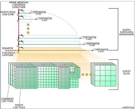
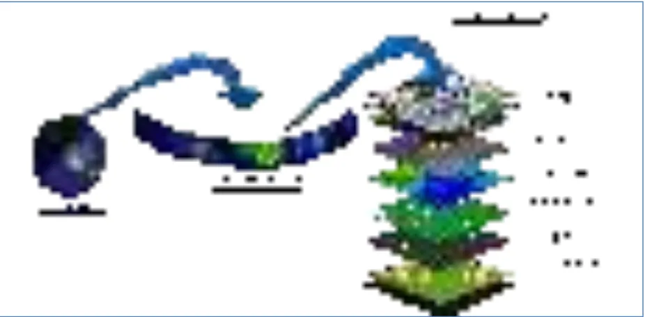
storage of any information contained within the CDB. The storage structure portion of the Specification geographically divides the world into geodetic tiles (bound by latitudes and longitudes), each containing a specific set of features (such as terrain altimetry, vectors) and models (such as OpenFlight models, RCS models), which are in turn represented by the datasets (see Figure 1-10: CDB Specification Tile/Layer Structure). The datasets define the basic storage unit used in a CDB. The geographic granularity is at the tile level while the information granularity is at the dataset level. As a result, the CDB storage structure permits flexible and efficient updates due to the different levels of granularity with which the information can be stored or retrieved
2. Layers: The CDB standard data representation model is also logically
organized as distinct layers of information. The layers are notionally independent from each other (i.e., changes in one layer do not impose changes in other layers).
3. Levels-of-Detail (LODs): The availability of LOD representations is critical to real-time performance. Most simulation client-devices can readily take advantage of an LOD structure because, in many cases, less detail/information is necessary at increasing distances from the simulated own-ship. As a result, many client-devices can reduce (by 100-fold or more) the required bandwidth to access environmental data in real-time. The availability of levels-of-detail permits client-devices to deal with databases having near-infinite content. The CDB standard is structured into an LOD hierarchy consisting of up to 34 LODs. The CDB standard requires that each geographic area be reduced into a LOD hierarchy in accordance to the availability of source data.
The Specification does not define or enforce an operating system or file system; nonetheless, the implementation of a CDB storage sub-system must conform to absolute minimum file system requirements called for by the Specification.
2
1.3.1.1 Use of CDB as an Off-line Database Repository
Figure 1-1: Use of CDB as an Off-line Database Repository, illustrates the deployment process of a CDB when it is used solely as an off-line Master database repository. This approach follows the SE deployment paradigm commonly used today within the simulation community. The use of the CDB as an off-line environmental data repository offers immediate benefits, namely…
SE Standardization through a public, open, fully-documented database schema that is already supported by several SE authoring tools.
SE Plug-and-Play Portability and Interoperability across various vendor SE authoring toolsets
SE Correlation through the elimination of source correlation errors through normalization of all data sets (a single representation for each dataset)
SE Re-use by eliminating dependencies that are specific to the simulation application, the Database Generation tool suite, the simulation program, the technology
SE Scalability which results in near-infinite SE addressability, spatial resolution and content density in each of the SE datasets.
3D Model Library Management through built-in provisions for the cataloging of models
SE Versioning Mechanism allowing instant access to prior versions and simplified configuration management
Cooperative SE Workflow through an internal SE structure which favors team work. The SE workflow can be allocated by specialty (e.g., altimetry, satellite imagery, vector data) or by geographic footprint.
Straightforward SE Archival and Recovery
Note that the use of the CDB as an off-line repository does not impose any change to the simulation training equipment (i.e., no modifications to client-devices are required3). However, the deployment of the synthetic environment is similar to the conventional approaches used in industry requiring the time-consuming, storage-intensive, off-line compilation of proprietary runtime databases to each client-device. Furthermore, the computing demands on the database generation facility are significantly greater because the entire database must be published off-line for each client-device before it can be deployed. These costs rapidly escalate with the
complexity and size of the synthetic environment, the number of supported client-devices and the number of supported training facilities. For complex databases, these costs can far outweigh the costs of the runtime publishers attached to each simulator client-device.
3
Figure 1-1: Use of CDB as an Off-line Database Repository
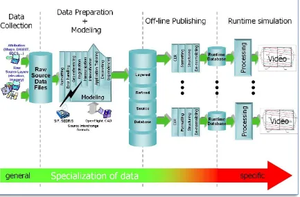
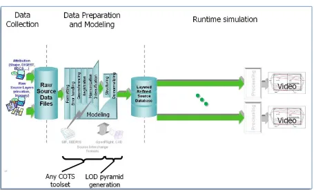
In most modern SE tool suites in-use today, the Data Preparation step shown in Figure 1-2: SE Workflow with CDB as an Off-line Database Repository consists of many sub-steps usually applied in sequence to each of the datasets (aka layers) of the SE. In effect, this aspect of the modeler’s responsibilities is virtually identical to that of a GIS4 specialist. As a result, many of the simulation equipment vendors offer SE authoring tools that integrate best-of-breed COTS5 GIS tools into their respective tool suites. The steps include:
Format conversion: raw source data is provided to modelers in literally hundreds of formats. Early on in the SE generation process, modelers typically settle on a single format per SE layer (e.g., terrain altimetry, imagery, attribution)
Error handling: raw source often contains errors or anomalies that, if left
undetected, corrupt and propagate through the entire SE data preparation pipeline. As a minimum, these errors must be detected early on in the process. More advanced tools can correct many of these automatically, particularly if there is some redundancy across the layers of data.
Data geo-referencing: this is the process of assigning a unique location (latitude, longitude and elevation) to each piece of raw data entering the SE pipeline.
Data Registration: each dataset is manipulated so that it coincides with
information contained in the other datasets. These manipulations include
4 Geographic Information Systems 5
projections, coordinate conversions, ortho-rectification, correction for lens distortions, etc. For images, this process is also known as rectification.
Data Harmonization: the raw data of a dataset varies over a geographic extent if it was obtained under different conditions, such as from two or more sensors with differing spectral sensitivity characteristics, resolution, in different seasons, under different conditions of weather, illumination, vegetation and human activity. The modeler must factor for these variations when selecting and assembling the datasets into a self-coherent SE.
Figure 1-2: SE Workflow with CDB as an Off-line Database Repository
The effort expended during the Data Preparation and Modeling step is mostly independent of the targeted simulation devices and the targeted applications. Consequently, the results of the data preparation step can be stored into a Refined Source DataBase (RSDB) and then re-targeted at modest cost to one or more simulation devices.
The standardization of RSDBs can greatly enhance their portability and re-usability.
While standardization of format/structure is essential to achieve high portability, inter-operability and re-use, the SE content must be ideally developed so that its content is truly independent of the training application. Therefore, we strongly recommend that the SE content of the CDB repository be developed to be independent of the training application.
Historically, SEs were developed for a single, targeted simulation application (e.g., tactical fighter, civil and air transport, rotary wing, or ground/urban warfare). In effect, the intended training application played an important role in determining the RSDB content because SE developers were constrained by the capabilities of the authoring tools and of the targeted simulation device. Unfortunately, this tailoring of SE was performed too early during the SE workflow and severely limited the applicability and re-use of the SE. Application tailoring can require either data intensification6 or data decimation7 . Note that the process of data
intensification and decimation lends themselves to computer automation and can be performed during the off-line publishing process. In the future, we anticipate some data intensification to be done in real-time time.
Once the SE developer has completed his work in creating the various data layers of the Refined Source DataBase, he must off-line publish (aka “compile”) the SE into one or more device-specific data publishing steps. As we will discuss in section 1.3.1.2, Use of CDB as a Combined Off-line and Run-time Database Repository, the device-specific off-line compilation step can be entirely omitted if the targeted training equipment is CDB-compliant.
While an off-line publishing approach does not offer all of the benefits described in section 1.3.1.1, it nonetheless provides an easy, low-effort, migration path to CDB. Any equipment vendor can easily publish the RSDB into his proprietary runtime format. Firstly, the publishing process is facilitated by the fact that the CDB specification internally use of industry standard formats (e.g., TIFF, JPEG, OpenFlight, and Shape). As a result, it bears much commonality with other database interchange formats. However, the CDB goes much further in that it “wraps” these formats into a global, standardized data model suited to high-end real-time simulations. This greatly facilitates the work of SE developers. Thus, the CDB provides a far simpler and straightforward means of interchanging refined source data, when compared to alternatives such as SIF, SEDRIS, OpenFlight that have partial pre-defined data models that are not sufficiently comprehensive for use in real-time simulations.
6 Data Intensification is the process of augmenting or deriving added detail from the information found in the
raw data. For instance, intensification can be used to augment flattened terrain imagery with 3D cultural detail relief. A typical example of this consisting in populating forested areas found in the terrain imagery with individual three-dimensional trees.
7
1.3.1.2 Use of CDB as a Combined Off-line and Run-time Database Repository
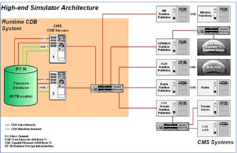
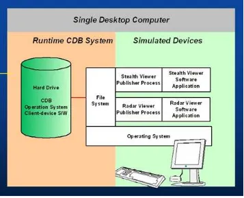
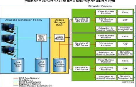
A CDB can be both used an off-line repository for the database authoring tools or as an on-line (or runtime) repository for the simulators. When used as a runtime repository, the CDB offers plug-and-play interchangeability between simulators that conform to the CDB specification. Since the CDB can be used directly by some or all of the simulator client-devices, it is considered a run-time environment database.
In addition to the benefits outlined in section 1.3.1.1, Use of CDB as an Off-line Database Repository, the use of the CDB as a combined off-line and run-time repository offers many additional benefits, in particular:
SE Plug-and-Play Portability and Interoperability across CDB-compliant simulators and simulator confederacies (be it tactical air, rotary, urban/ground, sea).
Reduced Mission Rehearsal Timeline by eliminating SE generation steps (off-line publishing, database assembly and data automation
Simplified Deployment, Configuration Control and Management of Training Facility SE Assets by eliminating the duplication of SE runtime DBs for each simulator and each client-device of each simulator.
Single, centralized storage system for the SE runtime repository (can be extended to a web-enabled CDB)
Seamless integration of 3D models to the simulator.
Fair Fight/Runtime Content Correlation through the adjustment of runtime level-of-detail control limits at each client-device.
Figure 1-3: Use of CDB as an Off-line and On-line Database Repository
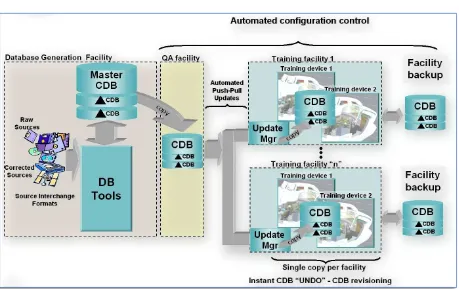
The CDB specification standardizes formats and conventions related to synthetic environments for use in simulation. However, many additional benefits can be garnered if the CDB is also used as an on-line database repository; this is particularly true when one considers the effort expended in the deployment of the synthetic environment to the training and/or mission rehearsal facilities.
When used as an on-line database repository, there is no need to store and maintain off-line published versions of the database for each client-device (as illustrated in Figure 1-3). As a result, the storage and computing demands on the database generation facility are significantly lowered. This is especially true of database generation facilities whose mandate involves the generation of complex synthetic environments for use by several training facilities.
Figure 1-4: SE Workflow with CDB as Combined Off-line/Runtime Database Repository
This approach permits the CDB representation of the synthetic environment to be “dissociated” from the resolution, fidelity, precision, structure and format imposed by the internals of client-devices. Compliancy to the CDB specification can be achieved either by modification of the client-device internal software to make it CDB-native or by inserting a runtime publishing process that transforms the CDB data into the client-device’s legacy native runtime format. In the later case, this process is done in real-time, on a demand-basis, as the simulator “flies” within the synthetic environment. Note that since the simulated own-ship moves at speeds that are bounded by the capabilities of the simulated vehicle, it is not necessary to instantly publish the entire synthetic environment before undertaking a training exercise; the runtime publishers need only respond to the demands of the client-devices. When the simulated own-ship’s position is static, runtime publishers go idle. As the own-ship starts advancing, client-devices start
demanding for new regions, and runtime publishers resume the publishing process. Publishing workload peaks at high-speed over highly resolved areas of the synthetic environment.
1.3.2 What the CDB Specification Is Not
The representation and sharing of synthetic environment data plays a key role in the interoperation of systems and applications that use such data. In the mid to late 90’s some specifications/standards were conceived to provide a means of sharing synthetic environment data, in source form, for a wide variety of applications. They provided a standardized means to share native databases, thereby avoiding direct and (often inefficient) conversion of the data to/from (often proprietary) native database format. Their mandate was about:
1. providing a representation of synthetic environment data for the modeling and simulation field; and
2. providing the means to freely interchange synthetic environment datasets. Such Specifications addressed the interchange of data, representing the simulated natural environment, in advance of the runtime use.
The CDB Specification, on the other hand, is primarily intended as a distributed simulator runtime synthetic environment database Specification. It is a Specification optimized for distributed simulation applications that require very large synthetic environment databases for use in high-end simulation, mission planning/rehearsal. The CDB Specification datasets extend the simulation beyond just “classic out-the-window” visualization since it supports the
simulation of sensors, such as FLIR, NVG, Radar and other simulation subsystems such as Computer Generated Forces and NAVAIDS.
The CDB Specification concerns itself with the modeled data representation and attribution of terrain, objects and entities within the synthetic environment. However, it does not concern itself with the movement, change in shape, physical properties and/or behavior of such objects and entities; this falls under the domain of synthetic environment simulations.
The CDB Specification does not concern itself with representations of celestial bodies (such as the Sun, Moon, stars, and planets). Rather, it assumes that the modeled representation (e.g., the Sun/Moon disk representation in an IG) of celestial bodies is internally held within the
appropriate simulator client-devices.
Due to its real time vocation, the CDB Specification limits the number of units of measure for each physical quantity. For instance, all terrain surface coordinates are represented in lat-long while all other distances are in meters. This is in stark contrast to DB interchange standards, which permits a large set of units for each physical quantity (for example distance can be expressed in feet, meters, miles, parsecs, light-years, nautical miles, inverse-meters, angstroms, microns).
current form, the CDB Specification does not mandate on synthetic environmental richness, quality and resolution.
Given the mandate of the CDB Specification to be platform independent, it cannot provide the implementation details of specific off-line database compilers or runtime publishers attached to specific client-devices. Furthermore, since there is no standardization of the SE representation internal to client-devices (they vary by type8, by vendors), it is unlikely that such information would completely satisfy the interests of all developers. More importantly, the structure and format of synthetic environment data ingested by each client-device is typically proprietary; as a result, it is impossible to fully describe the effort required to develop CDB off-line compilers and/or CDB runtime publishers.
1.3.3 What is a CDB
A CDB corresponds to a static synthetic representation of the whole earth; it is geographically divided of into geodetic tiles (bound by latitudes and longitudes), each containing one or more specific sets of features. It uses the WGS-84 earth model to provide geodetic interoperability. Each of the simulator client-devices accesses the CDB geospecific information using the WGS-84 geodetic coordinate system.
A CDB contains the features and modeled representation of the synthetic environment. It contains terrain altimetry; its raster imagery, its attribution as well as 3D feature with their modeled geometry, texture and attribution. The Specification also makes provision for the representation of moving models. The representation of moving models is comprehensive and goes well beyond other visualization standards because it makes provisions for the standardized simulator naming conventions, material and feature attribution, radar/laser reflectivity, aircraft and airport lighting systems, armaments, special effects, collision points/volumes just to name a few.
The Specification governs all aspects of the CDB, as follows:
Data content and representation of the synthetic environment Structure and organization of the synthetic environment File format of the synthetic environment as stored on media
The CDB Specification describes a modeled synthetic environment representation for distributed simulation applications. Section 1.6.5, Use of CDB in Applications Requiring Dynamic
Synthetic Environments discusses how a CDB-compliant simulator could be adapted to handle modifications of the synthetic environment in real-time.
Given the CDB’s structured representation and attribution of terrain, objects and entities, it is now possible to design a broad range of synthetic environment simulations that modify synthetic environments in real-time. Such simulations can modify the CDB and notify their changes to the other simulation federate that share a CDB. This provides a synthetic environment that is
persistent and fully correlated across all simulation federates. For example, terrain trafficability
8
could be handled by a new SE simulation that dynamically calculates soil moisture content as a function of localized rain precipitation and soil types/composition. A second simulation would then derive the resulting soil physics and determine vehicle wheel slippage across the varying terrain conditions.
The modification/notification approach is well-suited for a broad gamut of SE simulations; however, some simulations are very data intensive and would require excessive broadcasting bandwidths to other federates. In such cases, these dynamic simulations would have to be replicated in the other client-devices of the federation. Good examples of this are visual system special effects (e.g., rotor downwash effect, missile plumes, muzzle flashes, cast landing lights); typically such simulations are proprietary and intrinsic to the client-devices. Other examples of this include the varying effects of weather9 (local winds, temperature, humidity, particulates, etc.) and oceans (currents, temperature, etc.).
1.4 Key Features and Characteristics of the CDB Specification
The following paragraphs provide an overview of key features and characteristics of the CDB Specification.
1.4.1 Synthetic environment Database for Simulation Applications
The CDB Specification is a simulator-level synthetic environment database Specification for use in real-time. The Specification is open, platform-independent and client-device independent. The Specification defines all aspects of data representation and organization, and storage structure necessary to support full-mission real-time simulation. The CDB Specification synthetic environment databases contain datasets that represent the features of a synthetic environment for the purposes of simulation applications. The CDB provides a time-invariant synthetic environment representation of the earth, composed as terrain, natural/man-made features and moving models for use by SE authoring tools and simulators.
1.4.2 Logical Addressability
The CDB Specification provides for near-infinite addressability. The amount of information associated with a CDB is limited only by available disk storage. The CDB Specification allows for a nearly infinite number of identifiers within a single CDB. Addressability is not expected to be a limiting factor even if we assume a yearly doubling of storage capacity.
1.4.3 High Spatial Resolution and Scalability
The CDB Specification provides for near-infinite resolution due its organization of data in LODs. The CDB Specification grid-organized data (e.g., elevation, ground raster imagery, ground properties) is structured into an LOD hierarchy consisting of up to 34 LODs. Grid-organized data can be represented to a resolution of 13 microns.
9 Time-varying weather simulation effects could be simulated by a “weather server” simulation subsystem
The CDB Specification also provides for near-infinite cultural content. The CDB Specification for vector data (3D point, lineal and areal features) is also structured into a LOD hierarchy consisting of up to 34 LODs. At the finest possible LOD, a CDB can contain in excess of 100 million cultural features per square meter.
The CDB Specification permits each geographic area to be modeled at a distinct LOD in
accordance to the availability of source data. Since this capability is provided at a tile-level, it is storage-efficient.
1.4.4 Earth Geodetic Spatial Representation Model
Geo-referenced data constitute a major aspect of the CDB Specification synthetic environment data. It uses a geographic coordinate representation (WGS-84 lat/long, elevation) for the earth’s terrain surfaces and ocean floor. Furthermore, natural and man-made objects are positioned and oriented using geodetic coordinates. The CDB Specification provides geodetic coverage for the entire earth.
1.4.5 Tile/Layer/Level-of-Detail Structure
The CDB Specification offers a structure that is well suited for the efficient access of its contents. To this end, it relies on three important means to organize the synthetic environment data:
Tiles Layers
Level-of-Detail (LOD)
1.4.5.1 Tiles
The CDB Specification relies on a top-level tile structure designed to organize the data for efficient access in real-time. The tile structure provides an effective means for simulator client-devices to access the datasets of a geographical area at a selected LOD. Since the spatial
dimension of tiles varies inversely with LOD (i.e., resolution), client-devices can readily predict the amount of data contained within the tile; as a result, the management of memory within client-devices is simplified and much more deterministic.
The CDB Specification Data Representation Model (DRM) is logically organized as a strip of geo-unit aligned tiles along each earth slice. Each earth slice is divided into a decreasing number of tiles to account for the fact that the length of an earth slice decreases with increasing latitude.
1.4.5.2 Layers
The CDB Specification DRM is also logically organized as distinct layers of information. The layers are theoretically independent from each other, (i.e., changes in one layer do not impose changes in other layers).