SUPPORTING UAVS IN LOW VISIBILITY CONDITIONS BY
MULTIPLE-PULSE LASER SCANNING DEVICES
Ana Djuricic and Boris Jutzi
Institute of Photogrammetry and Remote Sensing (IPF), Karlsruhe Institute of Technology (KIT), Englerstr. 7, 76131 Karlsruhe, Germany
{ana.djuricic, boris.jutzi}@kit.edu
Commission I
KEY WORDS: UAV, laser scanning, multiple pulses, soft obstacles, cases of emergency
ABSTRACT:
Unmanned Aerial Vehicles (UAVs) are nowadays promising platforms for capturing spatial information, because they are low cost solutions, which are easy to bring to the surveying field and can operate automatically. Usually these devices are equipped with visual sensors to support the navigation of the platform or to transmit observations of the environment to the operator. By collecting the data and processing the captured images even an estimation of the observed environment in form of 3D information is available. Therefore Simultaneous Localization and Mapping (SLAM) algorithms are well known for processing data which is captured in the visible domain. However, situations can occur where gathering visual information is difficult due to given limitations in form of low visibility. For example if soft obstacles in form of translucent materials are given in disaster scenarios with smoke and operating has still to be ensured, active optical sensors (e.g. laser scanners) are gaining interest because they can penetrate the soft obstacle and allow to acquire information behind it. A new lightweight (210g), simplified and minimized scanning unit is now available which allows to capture multiple reflections for each transmitted laser pulse, namely the Hokuyo UTM-30LX-EW. With such a device, it is possible to overcome the above mentioned restrictions or limitations of low visibility by soft obstacles and even measure under critical circumstances. A multi-pulse system can provide accurate measurements on, within, and behind the soft obstacle. This research focuses on investigating the ability and performance of a laser scanner to penetrate the soft obstacle. Thus, investigations on a system that overcomes these limitations and provides a solution will be given. First promising experimental results considering soft obstacle are described.
1. INTRODUCTION
Nowadays laser scanning is one of the most used technologies for deriving 3D information. Depending on the application, a laser scanning unit can be designed and used in many different ways. Due to the developments, laser scanners are becoming very robust and small in size, and they can even be a light component integrated in a measurement unit which is easy to carry. Thus, laser scanning devices are becoming portable and excellent mobile support for unmanned aerial vehicles, which are promising platforms for capturing spatial information. Furthermore, these devices offer a low cost solution, which is easy to bring to the surveying field and can operate automatically. Their role is to reliably collect observations of the environment in different types of scenarios. Observing environment in the visible domain in order to capture the data in form of 3D information is now possible as well for situations where limitations are present in the form of low visibility. Usually, these situations are caused by different types of soft obstacles which are given by smoke, dust, fog, steam, rain or some other medium with particles (Figure 1). The possibility to overcome a limited depth of field is now possible (Ryde and Hillier, 2009). Hence, in cases when low visibility is given and operating still has to be ensured, active optical sensors (e.g. laser scanners) are becoming interesting because they can penetrate the soft obstacles and provide information behind these. The consideration of these capabilities offers a high potential, as the described situations might for instance occur in the following examples: a) in bad weather conditions if rain or fog appears, b) in industrial environments due to aerosols or dust, or c) in disaster scenarios with smoke.
In this paper, the investigation of a laser scanning unit under special recording conditions is presented. In contrast to works with single-pulse scanning units, this research focuses on a new multiple-pulse scanning unit in order to investigate its performance. For this purpose, an experimental scanning unit has been investigated which involves the small and light laser scanning device Hokuyo UTM-30LX-EW and a remote control motorized pan head rotating device mounted on tripod in order to support first steps during recording of multiple laser pulses. The measured data contains geometric and radiometric information represented as range and intensity values which are processed in order to obtain 3D information of the environment in form of a coloured 3D point cloud. Whereas the spatial 3D information represents the range to surfaces of observed objects, the measured intensity represents the energy of the backscattered laser pulse. The captured data is dense enough for a visual identification of the shape of observed objects.
The contribution of this paper is the investigation of the performance of a multiple-pulse scanning unit overcoming the above mentioned special conditions. For this purpose, the main objectives of this research are
to prove the ability to operate in specific conditions, to derive 3D point clouds from the geometric and
radiometric information that can be delivered by the laser scanner,
to obtain a 3D scene representation of the scanned object of interest in form of a point cloud in the visible domain and under low visibility conditions (Figure 1), and to specify the quality obtained during the investigation by
visual comparison of scenes involving a soft obstacle and the scene without soft obstacle.
Figure 1: Example of a possible scenario with soft obstacle.
The analyses of measured multiple laser pulses influenced by smoke during scanning within an indoor environment will be described in detail and investigated in following sections.
The paper is organized as follows: In Section 2, the methodology of the workflow to derive proper point clouds from the measurements is outlined. The performed experiments are described in Section 3 and the achieved results are presented in Section 4. Finally, in Section 5, conclusions and suggestions for future work are outlined.
2. METHODOLOGY
The presented methodology considers the investigation of ability and performance of the laser scanning device to penetrate distance through soft obstacle and demonstrates its capability of collecting adequate and accurate measurements for a possible case of emergency. This investigation is useful for applications in domains with low visibility due to weak lighting conditions, all weather types or different translucent materials in the air. The ability to measure objects in 3D under these conditions became increasingly important and interesting for possible cases of emergency over the last years. Thus, innovations and new methods are of interest for investigating a scanning unit that overcomes these limitations and provides a solution that will meet new demands for more advanced scanning.
2.1 Derivation of 3D point cloud measurements
The new generation of sensors, in addition to the geometric information (i.e. 3D position derived from range data) provides radiometric information (i.e. reflected intensity) about the objects of interest.
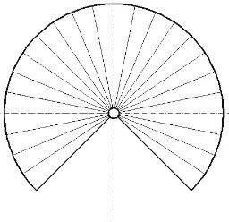
For calculating and determining a 3D point cloud the measured range is used and transformed as depicted in Figure 2 and Equation 1.
Figure 2: Polar coordinates.
Correspondingly, the polar coordinates are:
cos sin sin
cos sin
r z
r y
r x
(1)
where r = range (the distance from the origin)
xn, yn, zn = coordinates which determine the position of a point N
φ = the angle from the x-axis (azimuth angle)
ϑ = the angle from the z-axis (zenith angle)
Angles are defined and restricted by the following criteria:
0° ≤ θ ≤ 180° (π rad)
0° ≤ φ < 360° (2π rad)
In Cartesian coordinates, the position of a point N is given by its (xn,yn,zn) coordinate values, whereas in polar coordinates (shown in red) the distance r, and the angles φ and ϑ are used (Figure 2).
Concerning this, scanning units use two angles (φ and ϑ) during collecting multi-pulse range-intensity pair information. The
angle φ is given for horizontal field of view, the angle ϑ (up to
270 degree) is given for vertical field of view where only a scan line is captured.
Furthermore, not only geometric information in form of range data, but also radiometric information is available in form of reflected intensity data which is also encapsulated in the measured data (Figure 3).
2.2 Point cloud segmentation
Due the fact that the emitted pulse does not deliver only a first, but also a second and a third pulse return, i.e. due to echoes, the applied approach for segmentation of a laser range-intensity pair dataset includes the separation of multi-pulses derived from the measurements. Range and intensity for each returned pulse are segmented based on first, second and third pulse.
2.3 3D scene representation
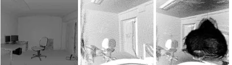
The range information is used to derive the respective 3D coordinates of the points (Section 2.1). Accordingly intensity, additional processing is carried out in order to normalize the measured intensity. The normalized intensity is depicted in Figure 3.
Figure 3: Overview of captured data: office room (left and middle: office without smoke, right: office with presence of
smoke cloud).
3. EXPERIMENT
The experimental section describes the acquisition of signals with the laser scanner Hokuyo UTM-30LX-EW and an overview of selected possible scenarios in practice for purpose International Archives of the Photogrammetry, Remote Sensing and Spatial Information Sciences,
of the research. The performed experiment shows capabilities to provide information behind the soft obstacle which appears between the laser scanning device and the object of interest. According to the specifications of the used device and based on the measurements obtained, with Hokuyo UTM-30LX-EW multi-pulse functionality is given.
Considering the fact that the Hokuyo laser scanner captures multiple reflections caused by a soft obstacle, such a device records the returns of first, second and third backscattered laser pulse. In this case, the measured first pulse is interpreted as part of the soft obstacle. While first pulse recording is related to measurements of objects out of partially penetrable or translucent materials, last pulse recording should measure non-penetrable object surfaces. This claim is proven by the performed experiment.
3.1 Laser Scanner device
Hokuyo’s size, lightweight and power consumption make the
device ideal for mounting on UAVs. The laser safety is class 1.
Model Light Source Detection Range Accuracy
Scan Area Resolution Scan speed
Protocol Weight
UTM-30LX-EW
Pulsed laser diode (λ=905 nm)
0.1 m to 60 m 0.1 m to 10 m +/- 30 mm
270º 0.25º SCIP2.2 210g (without cable) Table 1: Characteristics of the Hokuyo laser scanner device.
The laser has a 270º scanning area (Figure 4). The angle of scanning can be also preset by user, depending on the purpose of use (Hokuyo Specification 2012). The laser scanner operates by measuring the range and reflection of surfaces of the observed objects of interest for each angular step. It provides measurements with an angular resolution of 0.25º. 40 scan lines per second can be captured with 1080 measurements per scan line. Further it has multi-echo functionality which allows the capturing of multiple reflections per each transmitted laser pulse within a distance up to 60 m far away. Hence, this multi-pulse laser measurement unit can provide two types of information as range information and intensity information are available.
Figure 4: Scanned Area - 270°.
3.2 Scanning Unit
This section presents the established laser scanning unit consisting of the lightweight laser scanner device Hokuyo
UTM-30LX-EW and a remote control motorized pan head rotating device mounted on a tripod. This platform is used to rotate the laser scanner device during the measurements.
Figure 5: Laser scanner device with scanning unit.
The scanning unit also includes a moving platform which is shown above.
3.3 Scene description
A final test scene was chosen among various possibilities of potential cases of emergency (van Persie et al., 2011). The captured test scene covers the interior of the indoor room which contains office furniture, a potted flower and a person. The object of interest for the experiment is behind the soft obstacle (e.g. smoke).
Most of the man-made objects within the office are non-penetrable materials except a glass and the above mentioned soft obstacle. Their characteristics are reflected in the fact that they have different backscattering properties. Bringing a type of soft obstacle, for instance smoke, into this scene causes multiple reflections.
Analysing the visibility of the objects in form of range and reflectance for each corresponding point of backscattered pulse is possible for the collected data of the observed scene. The observed scene includes special conditions where the laser beam travels through the soft obstacle which is given by smoke. Single responses and multiple-pulses are investigated for an environment with low visibility due to smoke. The interactive scene related to the influence of soft obstacles is shown in Figure 6.
Figure 6: Test scenario in top view (blue points - first pulse returns (echo 1), red points - second pulse returns (echo 2)).
Figure 6 also shows that the emitted laser beam will pass through the soft obstacle to the object behind. One part of the International Archives of the Photogrammetry, Remote Sensing and Spatial Information Sciences,
beam will partially be absorbed and the remaining part will still go through the smoke cloud. This has a significant advantage: the scene, which cannot be captured by using a digital camera due to low visible conditions, can be easily obtained using a light laser scanner device.
3.4 Recording
The measurement data in one scan is a collection of measurements obtained for each measurement step. The captured data is directly stored on a computer, where it is also possible to monitor the scanned data in real-time. The form of data obtained for every step comprises multi-pulse range-intensity pairs. The scan data are looking accurate and indeed without much noise. Capturing the data was performed by rotating the laser scanner around the z-axis in the middle of the scene. The scanning unit was located within an office room itself as indoor environment. In some parts, certain scanned objects which have particular laser reflection are distorted. For instance, distortion occurs at objects with high reflectivity such as neon light lamps in the ceiling of the office. In addition it could be observed that the scanned points which were close to the Hokuyo device and show high laser reflections were more likely to be distorted during the scanning procedure.
The dataset recorded under the smoke condition demonstrates the possibility for achieving promising results in proving and explaining the statement that returned pulses arise from reflections at surfaces of observed objects such as the wall or other objects in an office or people in danger. This can be seen as one reflected pulse of emitted laser beam with wavelength 905 nm inside the office environment filled with dense smoke carries back the information of the reflected objects in the office and also people who may be inside, regardless of the presence of dense smoke. Thus, dense smoke does not affect the accuracy of the returned information. Reflections arising from the cloud of smoke result in certain range and intensity values, namely first pulses, but also range and intensity values of the surface of observed objects behind the cloud of smoke, namely the last pulses. The laser beam travels beyond our depth of field as well as beyond the depth of field of cameras. We or cameras are not able to see the scene through dense smoke. In contrast to us, or the camera, active optical sensors (e.g. laser scanners) can penetrate the soft obstacle and allow to provide information beyond the cloud of smoke. The laser beam is scattered by the particles in the air and for that reason multiple reflections from each affected small particles will be recorded as a new pulse, i.e. echo. Furthermore, another part of the laser beam (e.g. the received pulse from the wall) is reflected from the object of interest which is visualized during the observation. Evidently, wavelength 905 nm has potential to penetrate the soft obstacle such as smoke, which is proven by experiment.
4. RESULTS AND DISCUSSION
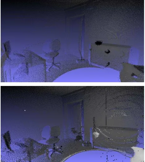
The experimental setup considers an office room as observed scene which is partly captured in the image in Figure 7 for the scene where no soft obstacles (only none penetrable surfaces) are given and the same scene with presence of dense smoke. The scans captured in both environments shown in Figure 7 are compared and first promising results are presented.
Figure 7: Example scene captured during the experiment; above: image captures one side of empty test office scene;
below: the same scene under smoke.
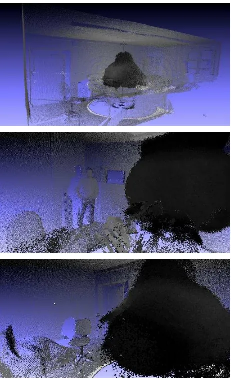
Figure 8: 3D point cloud colored by intensity of the soft obstacle (special low visibility conditions). International Archives of the Photogrammetry, Remote Sensing and Spatial Information Sciences,
The indoor situation with the presence of soft obstacle is illustrated. Influence of smoke on measurements is evident since the dark points in Figure 8 are coloured by returned intensity. Therefore, it is noticeable that points in the smoke cloud around the scanning unit are mostly affected and consequently changed in intensity. Figure 9 shows an example of the 3D point cloud colored by intensity of the soft obstacle (i.e. smoke) which is segmented separately in order to get only remaining point cloud colored by intensity of the none penetrable surfaces (wall, furniture, floor or ceiling) in Figure 10.
Figure 9: 3D point cloud colored by intensity of the soft obstacle (i.e. smoke).
The result demonstrates an effective segmentation of the soft obstacle derived from measurements. Obviously, a multi-pulse laser scanning unit has great performances to penetrate through the soft obstacle and excellent potential in succeeding to keep geometric information as well as the radiometric information of the walls in the room and the objects around, despite the fact that they are behind dense smoke cloud.
Figure 10: Example of a scene where smoke has been present, i.e. remaining point cloud colored by intensity of
non-penetrable surfaces.
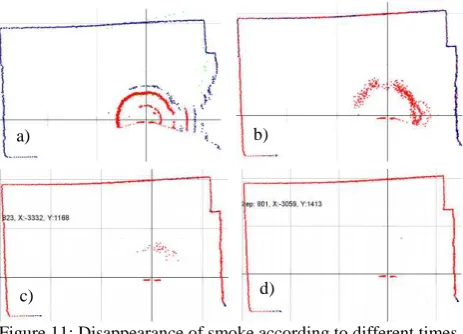
Since parts of the scene under dense smoke cloud are given, the pictures in Figure 11 show what happens with some of these parts when the smoke disappears gradually from the scene in a defined time period. Being sequentially captured, they show the orthogonal view of one scan line in the scene. Red points represent the first echo (which usually arises from the smoke cloud), blue points are the second echo (which are located mostly on the wall) and green points are the third echo. It can be noticed that the reduction in the number of second echoes (blue points) on the wall is evident.
Hence, the performed experiment provides a proof of the scanning unit ability to detect soft obstacles and penetrate through them, while keeping the wall geometry stable, i.e. without deforming its shape. Indeed, no major changes happen compared to the point cloud colored by intensity with the
non-penetrable surfaces (e.g. wall or furniture) and illustrated in Figure 12. Otherwise, the scanning unit will not have the ability to surmount the thick smoke, and due to that the surface of the wall would poorly be detected, be deformed or not detected.
Figure 11: Disappearance of smoke according to different times. Red points are first pulse returns, while blue and green points
are the respective second and third pulse returns.
Two measurements have been compared: a measurement captured in clear conditions and a measurement realised in the same environment but with smoke spread around, i.e. special low visibility conditions. The comparison includes checking the influence of the smoke on the measurements. Due to the multi-pulse ability of the scanning unit, the concentration of the smoke does not bring limitations to the measurements. The experiment carried out within this research indicates that the derived quality of the 3D points is quite sufficient.
Figure 12: Example of 3D scene without presence of soft obstacle (clear conditions), i.e. only none penetrable surfaces.
The example provided in Figure 13 clearly demonstrates that. A smoke cloud has been well segmented and removed from Figure 13 (bottom) leaving only the remaining point cloud after the performed segmentation. The resulting point cloud indicates that the methodology is applicable, because visual results give an enough accurate, respective and dense view of a 3D point cloud for further investigations and purposes.
Nevertheless, it was noticed due to the small distances within the office room when the object separation is large enough, the two reflections are sufficiently separated, so the detection of first and second reflection is clearer. Otherwise, the time between reflections is short and the two reflections overlap. In that case, the measurement is less relevant (Yoshitaka et al., 2006). It causes distortions on the wall as it can be seen in Figure 13 after performing the removal of the smoke cloud.
a) b)
c) d)
Figure 13: Comparison of two measurements.
However, the results can be promising fundamentals for the development of a navigation control algorithm for UAVs or robots which may lead to intelligent navigation. In that case, a laser scanning unit has significant relevance, as it considers multi-pulses. Thus, a UAV can still continue its flight route through a soft obstacle (e.g. fog, steam, dust or smoke cloud in the air), or on the contrary it can receive a warning about impenetrability of observed objects (e.g. hard wall) which are on the flight route (Castro and Peynot, 2012). Evidently, single pulses will be in fact information about hard or dense objects. Since the results provide sufficient information about the surrounding, that may be an important element for different operations during actions such as rescue, disaster management or monitoring non accessible zones or industrial inspection. Anyhow, investigations on this topic deserve further research attention.
The further plan is to mount the scanning unit on a mini copter, which is possible due to the small payload of these lightweight components and practical purposes. This requires further developments, as an experiment for data acquisition with an UAV also has to handle more complex motions such as translations or rotations. Applications involving UAVs are strongly motivated by the fact that over the last years, beside already wide and advanced military purposes, UAVs are becoming affordable for civil needs, not only in commercial campaigns, but also in research investigations (Wallace et al., 2012).
5. CONCLUSIONS AND FUTURE WORK
In this paper, a methodology has been presented for adequately capturing 3D point cloud data with a multi-pulse lightweight scanning unit under critical recording conditions arising from low visibility. For segmenting the captured range and intensity information, an approach based on first, second and third returned pulse has been applied. Thus, it is possible to distinguish between points of a soft obstacle (e.g. smoke) and points of an object of interest, i.e. none penetrable surfaces (e.g.
wall, furniture, floor or ceiling). The investigations are based on data captured within an indoor environment filled with a soft obstacle, i.e. an office room under smoke. The scanning unit can cope with the challenging environment and is still able to record data on the scene structure. Thus, the first results of the presented research on data captured with a multiple-pulse laser scanning device provide a proof of the performance of the utilized device and indicate that future research has great potential and attainable perspective in terms of improvement. As multi-pulse scanning units can provide measurements on, within, and behind a soft obstacle, new possibilities are given for measuring under critical, but realistic circumstances.
The future work could focus on possible hardware modifications and the development of advanced algorithms in order to make the laser scanning unit portable, for instance as component for UAV-based data acquisition. For further analyzing the obtained point clouds and thus more detailed scene analysis, it would be desirable to combine both geometric and radiometric information in order to exploit the arising synergies (Weinmann et al., 2013). Further investigations can be expected to achieve results which have great potential for measuring under critical recording conditions where a laser beam travels through different types of soft obstacles. Therefore, work will be continued in the future in order to develop and provide robust and valid support for UAVs.
REFERENCES
Castro, M.P.G. and Peynot, T., 2012. Laser-to-Radar Sensing Redundancy for Resilient Perception in Adverse Environmental Conditions. Australasian Conference on Robotics and Automation, Wellington, New Zealand, pp. 1-8.
Hokuyo Specification 2012. Scanning Laser Range Finder, UTM-30LX/LN Specification. www.hokuyo-aut.jp (last visit on 26.03.2013).
Ryde, J. and Hillier, N., 2009. Performance of Laser and Radar Ranging Devices in Adverse Environmental Conditions. Journal of Field Robotics 26(9), pp. 712-727.
van Persie, M., Oostdijk, A., Fix, J., van Sijl, M.C. and Edgardh, L., 2011. Real-Time UAV Based Geospatial Video Integrated Into The Fire Brigades Crisis Management GIS System. International Archives of the Photogrammetry, Remote Sensing and Spatial Information Sciences, Vol. XXXVIII-1/C22 UAV-g 2011, Conference on Unmanned Aerial Vehicle in Geomatics, Zurich, Switzerland.
Wallace, L., Lucieer, A., Watson, C. and Turner, D., 2012. Development of a UAV-LiDAR System with Application to Forest Inventory. Remote Sensing 4(6), pp. 1519-1543.
Weinmann, M., Dittrich, A., Hinz, S. and Jutzi, B., 2013. Automatic Feature-Based Point Cloud Registration for a Moving Sensor Platform. International Archives of the Photogrammetry, Remote Sensing and Spatial Information Sciences, ISPRS Hannover Workshop 2013, Hannover, Germany.
Yoshitaka, H., Hirohiko, K., Akihisa, O. and Shin'ichi, Y., 2006. Map Building for Mobile Robots Using a SOKUIKI Sensor - Robust Scan Matching Using Laser Reflection Intensity. International Joint Conference SICE-ICASE 2006 Bexco, Busan, Korea, pp. 5951-5956.