GROUND SURFACE VISUALIZATION USING RED RELIEF IMAGE MAP FOR A
VARIETY OF MAP SCALES
T. Chiba a , B. Hasi a*
a
Asia Air Survey Co., Ltd., Kawasaki, Japan – (has.baator, ta.chiba,)@ajiko.co.jp
Commission II, WG II/6
KEY WORDS: Ground surface, RRIM, Visualization, Digital Elevation Model
ABSTRACT:
There are many methods to express topographical features of ground surface. In which, contour map has been the traditional method and along with development of digital data, surface model such as shaded relief map has been using for ground surface expression. Recently, data acquisition has been developed very much quick, demanding more advanced visualization method to express ground surface so as to effectively use the high quality data. In this study, the authors using the Red Relief Image Map (RRIM, Chiba et al., 2008) to express ground surface visualization for a variety of map scales. The authors used 30 m mesh data of SRTM to show the topographical features of western Mongolian and micro-topographical features of ground surface in tectonically active regions of Japan. The results show that, compared to traditional and other similar methods, the RRIM can express ground surface more precisely and 3-dimensionally, suggested its advanced usage for many fields of topographical visualization.
topographical features. There are many methods to express topographical features of ground surface. Contour map has been a traditional method to express ground surface. However, contour map is very difficult to shows the detailed features in large scale map. Shaded relief map is also a traditional method to visualize ground surfaces, but the topographical features appears differently depend on the direction of light.
Upon the purposes of visualization for ground surfaces, more detailed methods are needed. In this paper, we use Red Relief Image Map (RRIM, Chiba et al., 2008) to express topographical features in various map scales. We used open data of 30 m mesh STRM1 released by NASA JPL to express large scale
2. VISUALIZATION USING RED RELIEF IMAGE MAP
The RRIM is a method to visualize ground surface by calculate openness (Yokoyama et al., 2002) and slope angle. The RRIM is independent from direction of incident light so there is no shadow of the map. RRIM shows 3D images by one image (no need to pair images and no need any additional devices). Even though the RRIM has no elevation and no information of slope direction, we can solve these problems combined overlapped contour map.
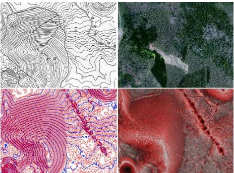
Compared to traditional methods for ground surface visualization, the RRIM shows a significant advantage. Figure 1 shows different features expressed by different methods in a same area (Chiba et al., 2008). The Figure 1 (d) revealed a very clear NW-SE directed fissures created by volcano eruption, expressed by RRIM. Figure 1(c) shows a contour map created by the same data with Figure 1(d), but too dense contour made it difficult to be read. Ortho photo is hard to understand the ground feature in densely covered forest region such like Japan (Figure 1b). The traditional contour map, due to its precision, is difficult to show micro topographical features (Figure 1a).
Figure 1. Comparison of RRIM and other methods. a)Contour map; b)Ortho image; c)Contour map from dense LiDAR data;
d) RRIM
3. LARGE SCALE LANDSCAPE EXPRESSED BY
RRIM IN WESTERN MONGOLIA
The topography of Mongolia is characterized by flat grassland in its eastern part, Gobi-desert in its southern part and The International Archives of the Photogrammetry, Remote Sensing and Spatial Information Sciences, Volume XLI-B2, 2016
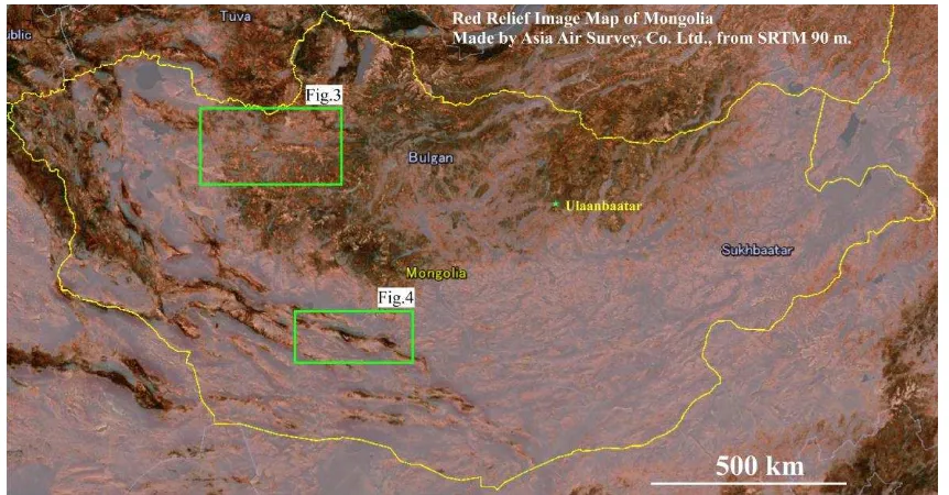
Figure 2. Topography of Mongolia. Created by SRTM3, 90m mesh digital elevation data (NASA), border line is from Google Earth).
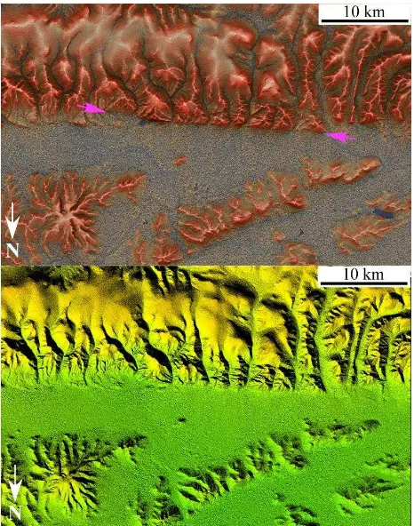
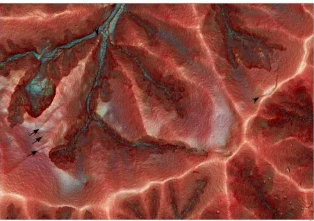
Figure 3. Topographical features along Bulnay fault. Pink arrows indicate fault lines.
Figure 4. Topographical features along the surface ruptures caused by Gobi-Altay earthquake. Pink arrows indicate fault lines. The International Archives of the Photogrammetry, Remote Sensing and Spatial Information Sciences, Volume XLI-B2, 2016
mountainous areas in its northern part and south western part. Figure 2 shows the landscape of Mongolia, the RRIM created from STRM3 of NASA and JPL. We selected two areas in western (Figure 3) and south western Mongolia (Figure 4) to show large scale the topographical features of Mongolia.
Two of the world’s largest recorded intracontinental earthquakes occurred in Mongolia in 20 century. One was the Bolnay Earthquake and Tsetserleg Earthquake occurred in 1905 (Okal, 1977; Pollitz et al., 2003). Figure 3 shows a part of fault lines of the 1905 Bulnay and Tsetserleg earthquakes. Very clear left lateral strike-slip surface ruptures could be recognized on the map. From the enlarged RRIM, we can clearly recognize the terminal facet (Figure 4) caused by the cumulated activities of the fault.
Another huge earthquake struck south western Mongolia, was the 1957 Gobi-Altay earthquake (Baljinnyam et al., 1993). Its seismic fault also can be observed on the RRIM (Figure 4) near Baga Bogd (Bayasgalan and Jackson, 1999).
Figure 5. Terminal facet along Bulnay fault. RRIM (upper) and color shaded map (lower)
Except clear surface ruptures in western and south western Mongolia caused by huge earthquakes in last century, we can also recognize other large scale features. Figure 6 shows a very interesting desert distribution in the western Mongolia. The desert is striking west-east and distributed along valleys. The desert may indicate some environmental changes such as Chiba et al. (2016) concluded in Balkhash lake in central Asia.
A gigantic paleolandslide was easily recognized in the northern slope of the Baga Bogt mountain in south western Mongolia (Figure 3 and Figure 7). The landslide occurred along the active
fault of Baga Bogd, possibly caused by a very strong earthquake (Philip and Ritz, 1999).
Figure 6. Desert distribution in western Mongolia. RRIM (upper) and color shaded map (lower)
Figure 7. Baga Bogd landslide. Pink arrow indicates the moving direction of the landslide.
4. MICRO FEATURES IN TECTONICALLY ACTIVE
AREAS IN JAPAN
Japan is a tectonically very active region in the world due to it located in a junction of four major tectonic plates. After suffered the 2011 Off the Pacific Coast of Tohoku Earthquake (JMA, 2011), south western Japan, Kumamoto Prefecture and its surrounding areas were suddenly stroke by several moderate to strong earthquakes in April, 2016 (JMA, 2016). To express The International Archives of the Photogrammetry, Remote Sensing and Spatial Information Sciences, Volume XLI-B2, 2016
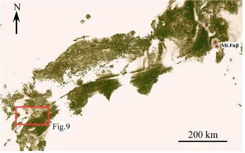
Figure 8. Topography of South Western Japan, made from GTOPO30.
Figure 9. Topographic features of the region involves the 2016 Kumamoto earthquake. Stars indicate epicentres of main earthquakes, a)The M6.4 earthquake occurred on April 14, 2016; b) The M6.5 erthquake occurred on April 15, 2016, c)The M7.3 earthquake
occurred on April 16, 2016. Red lines indicate urban active faults (AIST, 2012).
topographical features in regions which densely covered by forest, we created RRIM using a data set of 5 m and 10 m DEM from GSI, Japan . Figure 9 shows the topographical features around the region there involved the 2016 Kumamoto earthquake (JMA, 2016; GSI, 2016). A set of very clear active
fault segments can be recognized from the south western slope of the Mt. Aso to the flat area near the sea. The NE-SW striking faults were considered to be the source faults of the several moderate to strong earthquakes that stroke the Kumamoto The International Archives of the Photogrammetry, Remote Sensing and Spatial Information Sciences, Volume XLI-B2, 2016
region and its surroundings, caused serious damage to the region due to strong motion and accompanied landslides.
5. DISCUSSION AND CONCLUSIONS
In this study, we expressed ground surface using the RRIM, a visualizing method which invented more than ten years ago (Chiba and Suzuki, 2004, Chiba et al., 2008). The method can be used to interpret ground surfaces, hazard mapping, and using as background map any shows topographical features, overview large scale area to small area. This study suggested that the SRTM1 , a 30 m mesh open data, can be used to illustrate topographical features, such as surface ruptures or the deformations applying appropriate visualization methods, especially in dry area such as Mongolia to detect large scale deformation of surface ruptures or other topographical features in large map scale, such as in Figures 3 to 7. For regional scale, more detailed data could be better to express topographical feature. A hybrid data set of 5 m and 10 m mesh DEM, RRIM suggested a very useful to express the features in tectonically active region such as in Japan.
Regard to micro scale map, for detect more small to micro small cracks can be detected clearly. It suggested that the RRIM still significantly useful to express micro deformation.
For the problem that the RRIM has no elevation factor, we can combine other methods such as overlap contour map on RRIM to overcome the problem.
This paper demonstrated the RRIM can be used to express topographical features using relatively low resolution open data in a large map scale and use high resolution Airborne LiDAR data to detect micro topographical features, suggested the method is significantly useful method to be used.
Figure 10.A RRIM from 1 m mesh DEM from Airborne LiDAR.
REFERENCES
AIST (National Institute of Advanced Industrial Science and Technology), 2012. Active Fault Database of Japan, February 28, 2012 version. Research Information Database DB095 https://gbank.gsj.jp/activefault/index_e_gmap.html (17 Apr. 2016).
Baljinnyam, I., and 10 others, 1993. Ruptures of major earthquakes and active deformation in Mongolia and its surroundings. Geological Society of America Memoir 181, 62 p.
Bayasgalan, A. and Jackson, J., 1999. Field examples of strike-slip fault terminations in Mongolia and their tectonic significance. Tectonics, VOL. 18, NO. 3, pp. 394-411.
Chiba T, Kaneta S, Suzuki Y, 2008. Red Relief Image Map: New visualization method for three dimensional data. In:The International Archives of the Photogrammetry, Remote Sensing and Spatial Information Sciences, Baijing,China, XXXVII,B2, pp.1071-1076.
Chiba, T., Endo, K., Sugai, T., Haraguchi, T., Kondo, R. and Kubota, J.,2016. Reconstruction of Lake Balkhash levels and precipitation/evaporation changes during the last 2000 years from fossil diatom assemblages. Quaternary International, 397, pp.330–341.
Chiba T. and Suzuki, Y., 2004. Red Relief Image Map, a new ground surface visualization method, Proceedings of applied survey technology, 15, pp.81-89.
GSI, 2016. Information about the e2016 Kumamoto earthquakes http://www.gsi.go.jp/BOUSAI/H27-kumamoto-earthquake-index.html (17 Apr. 2016).
JMA (Japan Meteorological Agency),2011. 2011 off the Pacific coast of Tohoku Earthquake
http://www.data.jma.go.jp/svd/eqev/data/2011_03_11_tohoku/ (April 7, 2016).
JMA,2016. Related information about the 2016 Kumamoto earthquake
http://www.jma.go.jp/jma/menu/h28_kumamoto_jishin_menu.h tml (April 7, 2016).
Okal, Emile A., 1977. The July 9 and 23, 1905, Mongolian earthquakes: A surface wave investigation. Earth and Planetary Science Letters, 34 (2): pp.326–331.
Philip, H. and Ritz, J.F., 1999. Gigantic paleolandslide associated with active faulting along the Bogd fault (Gobi-Altay, Mongolia). Geology, 27, pp.211-214.
Pollitz, F., Vergnolle, M. and Calais, E., 2003. Fault interaction and stress triggering of twentieth century earthquakes in Mongolia. Journal of Geophysical Research ,108 (B10, 2503), pp.1-14.
Yokoyama, R. Shirasawa, M. and Pike, R.J., 2002. Visualizing topography by openness: A new application of image processing to digital elevation models. Photogrammetric Engineering and Remote Sensing, 68, pp.251-266.