Towards a Model-Driven Approach to Reuse
Robert B. France Computer Science Department
Colorado State University Fort Collins, CO, 80523, USA
+1 970 491 6356 [email protected]
Sudipto Ghosh
Computer Science Department Colorado State University Fort Collins, CO, 80523, USA
+1 970 491 4608 [email protected]
Daniel E. Turk
Computer Information Systems Colorado State University Fort Collins, CO 80523, USA
+1 970 491 0467 [email protected]
May 7, 2001
Abstract
A model-driven reuse approach that is based on an organization’s Enterprise Architecture (EA) and on the Unified Modeling Language (UML) is proposed. The framework embodying the approach allows an organization to evolve from a repository-based approach to a model-based reuse approach in which reusable experiences are embedded in modeling languages as an application domain becomes more stable and well-understood over time. In its fully mature form, the reuse infrastructure, called a ReSyDE (Reuse-based System Development Environment), consists of a repository of reusable modeling artifacts, and language front-ends for assembling repository artifacts into requirements and design models.
Keywords: Enterprise architecture, domain analysis, role models, software reuse, UML
1
Introduction
The systematic reuse of artifacts across a development lifecycle can yield order-of-magnitude improvement in development productivity. Implemented reuse practices and experiences have yielded the following in-sights:
Reuse of domain-specific experiences can significantly enhance development productivity and quality [2]. Reusable experiences can be classified as vertical or horizontal. Horizontal reuse occurs
when reusable artifacts are created for and used in a variety of application domains. Design patterns (e.g., see [13, 20]) and software architectures (e.g., see [4, 5]) are examples of horizontal experiences packaged for reuse. Vertical reuse occurs when development experiences within a clearly defined ap-plication domain are reused. When compared to horizontal artifacts, domain-specific artifacts for a mature domain1 are easier to build, and can cover a wider range of development phases, primarily because of their restricted scope. Domain-specific programming languages (DSPLs) [25] provide ex-amples of vertical reuse. A DSPL provides a language interface for assembling domain-specific code components into programs.
1
Reuse of development artifacts above the code level can significantly reduce development cy-cle time [3]. There is a growing realization that development cycy-cle times can be significantly
short-ened if reuse opportunities are exploited in all phases of software development; not just in the coding phase [3, 17, 21]. In the past, a barrier to the reuse of experiences above the code level was the lack of widely-accepted notations for representing requirements and design artifacts. The advent of the Uni-fied Modeling Language (UML) [19] as a de-facto industry object-oriented (OO) modeling standard has the potential to remove this barrier.
Effective reuse requires good support for finding, adapting, and incorporating reusable artifacts into project deliverables. For reuse to be effective it is important that software developers understand
when and how to apply the reusable development experiences. In a traditional repository-based ap-proach to reuse, the tasks of selecting, tailoring and integrating reusable experiences into project deliv-erables are explicitly carried out by developers in conjunction with other development activities. These reuse tasks are nontrivial and, if not properly supported, can be time consuming. Novice “reusers” have the additional task of learning about the available artifacts in the repository.
The above observations motivate our approach to systematic reuse. The approach has three primary char-acteristics:
It uses an enterprise’s Enterprise Architecture (EA) to structure reusable artifacts.
It supports reuse of models in a model-driven approach to system development.
It supports evolution of an organization’s reuse capability from a repository-based approach in which
developers search for reusable artifacts to one in which developer’s use modeling language front-ends to assemble reusable artifacts into requirements and design models.
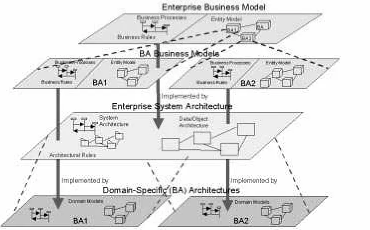
An EA (Enterprise Architecture) is a model that provides a map of an organization’s computer-based systems, and a mapping of business goals to the systems that accomplish them2. Fig. 1 shows our view of
the parts of an EA. The Enterprise Business Model is a model of business processes from an organizational perspective. It represents an integration of the business processes within each of an organization’s Business
Areas (BAs) (e.g., Customer Care, Billing). The Enterprise System Architecture consists of models
describ-ing (1) the static structure of an organization’s systems, and (2) the interactions that take place among the systems. A BA (Business Area) Architecture is an elaboration of the parts of an Enterprise System Archi-tecture that pertain to the BA. The thick arrows depict the mapping of the business-level concepts to their realizations at the system level.
An organization’s EA is intended to define the context in which system development projects are per-formed. The reuse framework proposed in this paper exploits the structure imposed by an EA to identify, classify, deploy and manage reusable artifacts in a repository-based reuse infrastructure.
Section 2 gives an overview of the reuse environment, which is described in more detail in sections 3 and 4. Related work in this area is described in section 5. In section 6 we conclude with an outline of our plans to further develop our reuse approach.
2
ReSyDE Overview
The reuse environment proposed in this paper is called a Reuse-based System Development Environment (ReSyDE). Using a ReSyDE, an organization can build a reuse infrastructure that initially supports a
tra-2
Figure 1: Outline of an Enterprise Architecture
ditional repository-based reuse environment3, and evolves towards a development environment in which de-velopment experiences are incorporated into the modeling notations and techniques used by system devel-opers in an application domain. The ReSyDE is based on the premise that as development experiences in an application domain matures (i.e., changes in fundamental concepts and design structures occur infrequently and expert developers have a deep understanding of the fundamental concepts) the opportunities for creating high-quality forms of reusable artifacts that span software development phases increases.
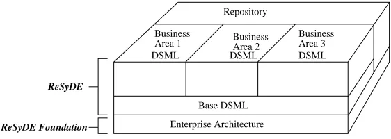
A ReSyDE consists of two key elements: a repository of reusable artifacts that span development phases, and a set of domain-specific modeling languages (DSMLs) that provide modeling interfaces to the reposi-tory. Fig. 2 shows the foundation and major components of a ReSyDE that can be used in a mature reuse environment.
A DSML is a modeling language that is used to assemble repository artifacts into system/software mod-els. During a development project DSMLs are used to develop and refine models of the system under devel-opment. Reuse is implicit in the use of a DSML: DSML constructs encapsulate mechanisms for retrieving, composing, and tailoring artifacts in the repository. Use of DSMLs results in an environment in which reuse activities are seamlessly woven into the modeling notations and techniques.
A DSML for a BA (business area) can be based on an organization-wide base DSML. The base DSML constrains the definition of BA DSMLs to ensure consistency with an organization’s Enterprise System
Business
Area 1 BusinessArea 2
Business Area 3 Repository
Enterprise Architecture
DSML DSML DSML
ReSyDE
ReSyDE Foundation
Base DSML
Figure 2: Essential Structure of a ReSyDE
chitecture (see Fig. 1) and modeling standards. In a ReSyDE, the base DSML can be the full UML or a specialized form of the UML. The BA DSMLs further specialize the base DSML.
DSMLs are possible in domains in which there exists a significant amount of stable, development ex-periences that can be codified. Such exex-periences can be built up if the organization actively “learns” by (1) monitoring its repository-based reuse environment, (2) adding new, and modifying existing reusable artifacts based on lessons learned, and (3) incorporating the experiences into development notations and techniques. The EA of an organization provides the foundation for a ReSyDE (see Fig. 2). The EA provides the ba-sis for (1) identifying application domains within an organization, (2) identifying reuse opportunities within domains, (3) classifying reusable artifacts within a repository, and (4) building DSMLs.
3
Developing an EA-based Reuse Repository Infrastructure
An effective repository-based reuse infrastructure must provide mechanisms that support Domain
Engineer-ing (DE), that is, the process of creatEngineer-ing, deployEngineer-ing, and evolvEngineer-ing domain-specific reusable artifacts. DE
includes (1) analyzing the domain to determine reuse potential (domain analysis), (2) developing and pack-aging artifacts for reuse, and (3) making the artifacts accessible to potential users.
3.1 Domain Analysis
Domain Analysis (DA) is concerned with analyzing and modeling a domain in order to identify potentially
reusable artifacts. The DA process in our approach produces the following outputs:
1. Domain models: Domain models capture the structural aspects of the domain in terms of domain con-cepts and their relationships. Such models can be used to reflect knowledge pertaining to (1) common-alities and variations across the functional areas of the domain, and (2) relationships between domain concepts across different levels of abstraction.
2. Domain development rules (DDRs): The DDRs reflect knowledge about how concepts in the domain are composed, analyzed and realized. The composition rules determine how domain concepts can be combined to form more complex domain concepts. The analysis rules determine what can be inferred from domain concepts, and realization rules capture knowledge pertaining to how domain concepts are implemented at lower levels of abstraction.
BA business models and domain-specific architectures provide good starting points for developing domain models.
Domain models and DDRs are expressed in the UML. DDRs are reflected in constraints expressed in the OCL [18], and in traceability, abstraction, and realization relationships among domain concepts. A do-main model is presented in terms of two views: a static, structural view called a Conceptual Model, and a behavioral view called a Functional Model. A Conceptual Model identifies domain concepts and the rela-tionships among them, at various levels of abstraction. It is a variant of the UML Class Diagram in which stereotyped classes represent concepts in the domain. A Functional Model can consist of variants of UML Activity Diagrams, Interaction Diagrams, and Use Cases that describe the behavioral aspects of a domain. The Functional and Conceptual Models distinguish aspects/features that are common and that vary across applications in the domain (UML tag definitions and stereotyped UML constructs are used for this purpose). Both Conceptual and Functional models describe domain concepts across abstraction levels. UML ab-straction and realization relationships are used to relate concepts across abab-straction levels, while traceablility relationships are used to relate concepts across different models.
3.2 Representing Reusable Models
In a ReSyDE, the EA provides the framework for organizing the reusable artifacts. Reusable experiences that are applicable across the organization can be represented at the enterprise level. Experiences that are specific to a domain (BA) within an organization are represented at the business area level. When a reusable feature is identified in a domain model produced in the DA activity, reusable artifacts representing the feature at various levels of abstractions, can be developed for the feature. Reuse of a model at a particular level of abstraction can lead to reuse of lower level artifacts in the repository.
The approach to creating reusable models in a ReSyDE is based on a view that reusable models are pat-terns. In our work, a reusable model is a characterization of model instances referred to as realizations. A packaged reusable model consists of two parts:
1. Usage context: This part consists of a narrative description of the situations in which the reusable model can be applied, and the consequences of using the reusable model.
2. Structural and behavioral models: This part consists of role models that characterize realizations. A role is a set of properties, and a model element that plays (realizes) a role must have at least the properties defined in the role. A model element that plays a role is referred to as a realization of the
role. A role-consistent model element is one that is capable of playing a role. A model element that is role-inconsistent with respect to a role does not have all the properties needed to play the role. Creating
a realization from a role model involves defining model elements and associating them with their roles in the role model.
role can also be associated with properties (expressed as a constraint on the UML metamodel association and association-end elements) that can be used to determine multiplicities of associations in role-consistent class models.
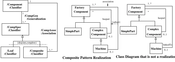
An example of a CRM representing a simplified composite reusable model is shown in Fig. 3. The only meta-model constraints are those expressed as role types and the multiplicities on the association roles. Fig. 3 also shows a realization of the reusable model, and a model that is not a realization of the reusable model.
1
class that plays the Component Role) (Machine can only be associated with one
Factory
Class Diagram that is not a realization Composite Pattern Realization
Figure 3: CRM for a Simplified Composite Reusable Model
The leftmost diagram in the figure is a CRM with five non-abstract roles: the classifier roles
Compo-nent, Leaf, Composite, and the relationship roles CompGen, and CompAssoc. All realizations of the abstract
CompSpec role are realizations of either Leaf or Composite (but not both), as indicated by the disjoint and
complete constraints. The relationship role between the Component role and the CompSpec role indicates
that realizations of the CompSpec role (i.e., realizations of Leaf and Composite roles) must be specializations of Component Role instantiations. The multiplicity on this relationship role indicates that a realization of a CompSpec role is a specialization of exactly one realization of the Component role, and a realization of the Component role can be specialized by one or more realizations of the CompSpec role. A realization of the Composite role must have an association relationship with exactly one realization of the Component role.
The middle diagram in Fig. 3 is an example of a Class Diagram that is a realization of the CRM on its left. In the model, the association between Machine and Factory Component is a specialization of the haspart association (i.e., the specialized association is a subset of the haspart association). The mapping of classes to roles used in this example is given below:
The Factory Component plays the role of Component.
SimplePart plays the role of Leaf.
Complex Component plays the role of Composite with respect to Factory Component and the role of
Component with respect to Machine.
Machine plays the role of Composite.
The generalization relationships between Factory Component and its subclasses, and between
Com-plex Component and its subclass, each play the role of CompGen.
The associations between Complex Component and Factory Component, and between Machine and
The mapping of classes to roles used in the rightmost diagram is given below:
The Factory Component plays the role of Component.
SimplePart plays the role of Leaf.
Complex Component plays the role of Composite with respect to Factory Component and the role of
Component with respect to Machine.
Machine plays the role of Composite.
The generalization relationships between Factory Component and its subclasses, and between
Com-plex Component and its subclass, each play the role of CompGen.
The unrelated haspart and linkedTo associations each play the role of CompAssoc.
The rightmost model is not a realization of the CRM (with respect to the given mapping) because a real-ization of the Composite role, Machine, has two different associations with a realreal-ization of the Component role (Factory Component): linkedTo and the inherited haspart. This violates the multiplicity constraint on CompAssoc in the CRM. Note that one has to know the mapping between model elements and roles before determining if a model is a realization of a CRM.
One can also build reusable models by incorporating role model elements into standard UML models (e.g., class diagrams, activity diagrams, collaboration diagrams). We refer to these models as hybrid role models (they consist of both roles and standard UML elements). For example, a reusable design class di-agram can be created by using roles to indicate model variation points, that is, the parts of the design that must be tailored when reused. Tailoring the reusable design to a particular usage involves realizing roles with model elements that play the roles. Roles can also be used to define design frameworks. The roles in a framework characterize the design elements that can be used within the framework. A particular design can be obtained from such a framework by plugging in role-consistent elements.
3.3 Deploying Reusable Artifacts
Good classification schemes enable efficient searches for, and retrievals of artifacts from the repository. Un-less artifacts can be found easily, they are unlikely to be reused in practice. The classification scheme used in our work with our industrial collaborator, is based on an EA that is a derivative of a telecommunication industry standard called the Telecom Operations Map (TOM) [10].
The TOM identifies function/service areas of a telecommunication business and breaks them down into sub areas and processes. An EA can utilize the TOM to map business functions to their computer-based implementations within an organization. Such an EA provides a framework for searching a repository for reusable artifacts. Reusable artifacts are organized into functional areas (BAs), and within each functional area, the artifacts are organized at various levels of abstractions.
4
Towards DSML-based Reuse Environments
The approach outlined in the previous section supports a traditional repository-based reuse environment in which developers search the repository for candidate artifacts, select an artifact, tailor the artifact, and incor-porate the artifact into the project deliverable they are working on.
artifacts. The DSMLs of a ReSyDE are intended to make as much of the reuse activity implicit through use of languages that encapsulate mechanisms for retrieving, tailoring and incorporating repository artifacts. A DSML can be viewed as a language front-end for assembling repository artifacts into models.
4.1 Domain Engineering for DSMLs
The DA process for DSMLs builds upon the results of the DA process used to develop repository artifacts. Inputs include reusable artifacts for the domain drawn from the repository, and domain models for the do-main (created when the dodo-main was analyzed for reusable artifacts). The output is a dodo-main theory which consists of (1) metamodels describing syntactic and semantic aspects of the models used within the domain, and (2) DDRs expressed in terms of metamodel elements. The domain theory is used in the Domain Lan-guage Engineering activity to produce the following:
1. Augmented metamodels that describe (1) the abstract and concrete syntax of the language, and (2) the semantic structure of the language. The metamodels are augmented with information needed to fully define the semantics of the language.
2. Mechanisms for analyzing models via transformations (e.g., see [9]).
3. Mechanisms for realizing/refining models (e.g., domain-specific compilation mechanisms for gener-ating code from DSML models).
4.2 Using UML Profiles to define DSMLs
Variants of the UML are used to (1) create models of domains and reusable models, and (2) express DSMLs. The UML has three extension mechanisms that can be used to create variants of its constructs: (1) a constraint language (OCL) [18] that can be used to express additional properties of modeling elements, (2) a tag defini-tions mechanism that allows one to add information to a modeling element, and (3) the stereotype mechanism that allows one to specialize a modeling element. For example, one can create UML-based DSMLs by us-ing stereotypes of UML modelus-ing elements to represent domain-specific concepts, and tag definitions and constraints to define relevant properties of the domain-specific modeling elements.
There is evidence that UML extensions in their current form are not powerful enough to support the domain-specific variants that we want to develop in our research [8]. The most serious limitations can be attributed to the lack of precise semantics for these extension mechanisms. This problem is further com-pounded by the lack of precise semantics for the UML notations [11, 23]. Extending or modifying informally defined notations can lead to confusion over the intended interpretations of the variants.
Our approach to tackling these problems is based on two central ideas: use of a precise UML core [11, 12] and use of profile [1] and preface [7] concepts to define precise variants of the UML.
The development of a precise core UML is currently the focus of a group of researchers called the precise
UML (pUML) group. Recently the group proposed a major restructuring of the UML in which core concepts
are identified and precisely defined, and variants of the UML syntax and semantics are expressed in a struc-tured manner through the use of profiles. In this sense, the UML becomes a family of languages, with the core UML being the common denominator. At the time of writing, this idea is the basis of a proposal, spear-headed by IBM and other major companies within the Object Management Group (OMG), for the next major revision of the UML (UML 2.0) [6].
UML constructs. A profile is defined by the OMG as a “predefined set of Stereotypes, TaggedValues, Con-straints, and notation icons that collectively specialize and tailor the UML for a specific domain or process ...” [1]. An OMG profile consists of a a subset of the UML metamodel, well-formedness rules over and above those specified for the UML, stereotypes of UML model elements, semantics for the language elements, and UML model elements expressed in terms of the profile. The current OMG notion of a profile restricts how the UML can be specialized. A profile should not add new elements or properties to the UML metamodel and the specialized semantics should be consistent with existing semantics. It is not clear from the UML standard what is meant by specializing UML semantics using profiles.
The notion of a preface seems to broaden the OMG notion of a profile. A preface will allow language developers to tailor, specialize, and extend the UML metamodel, the abstract syntax, the semantics, the con-crete syntax, the context conditions on the preceding elements, and define the allowed transformations and generations on UML models. Unlike OMG profiles, prefaces allow for modification of the metamodel, and they allow changes in the way the models are analyzed and transformed. Like OMG profiles, prefaces are informally described.
5
Related Work
Current works on domain-specific languages [25] focus on providing language interfaces for assembling code components into programs. Other forms of reusable experiences packaged for vertical reuse are frame-works [22] and domain-specific architectures (e.g., see [14, 16, 24]). We are not aware of any frame-works that attempt to weave vertical reuse artifacts into modeling notations such as the UML to produce DSMLs.
In the software engineering community there is a considerable body of work on domain engineering pro-cesses and domain modeling notations (e.g. see [2, 14, 24]). Our work builds upon these approaches to produce (1) UML-based notations for domain modeling, (2) techniques for building reusable models based on the notion of a role, and (3) techniques for building DSMLs.
While repository-based approaches to reuse are common, the reuse environment described in this paper differs from others in the following respects:
1. The development and resulting structure of the repository are based on an organization’s EA. Given that an EA provides the context in which system development is carried out within an organization, its use as a basis for developing reuse infrastructures ensures that reuse activities are closely aligned with the organization’s system evolution goals.
2. The UML is used as the basis for (1) representing domain models, (2) representing reusable artifacts above the code level, and (3) developing DSMLs. The notion of roles is used to support the creation of reusable UML-based models: Roles are used in models to indicate model variation points, that is, the parts of a model that can be varied (variation points described in [15] have a similar purpose). Metamodels expressed in the UML are used to define DSMLs.
6
Conclusion
In this paper we outline an approach to implementing a reuse infrastructure based on the UML and an or-ganization’s EA. Our approach utilizes the EA of the organization to identify, structure, and deploy reusable artifacts. The EA also provides the basis for building modeling language front-ends to a repository of reusable artifacts (DSMLs).
The long-term objective of our research is to create a framework that supports systematic development of ReSyDEs. The development of such a framework must be based on experiences accumulated through the implementation of ReSyDEs in industry if it is to be useful. For this reason, we are taking an experience-based approach to meeting our long-term objective: research results will be applied and evaluated in an in-dustrial context, and the experiences used to evolve the framework. We are currently developing a ReSyDE for a large telecommunication company. We expect the techniques we use for building reusable models and DSMLs will evolve as we learn from their application in the industrial setting.
Our current research is focused on developing a formal foundation for defining UML profiles to support their use in defining precise DSMLs. We are also developing transformation techniques that can be used to support the generation of code from models expressed in DSMLs.
References
[1] Analysis and Design Platform Task Force. Requirements for UML profiles. Technical Report ad/99-12-32, Object Management Group, 1999.
[2] G. Arango and R. Prieto-Diaz. Introduction and overview: Domain analysis concepts and research directions. In Domain Analysis and Software Systems Modeling. IEEE Press, 1991.
[3] V. R. Basili and H. D. Rombach. Support for comprehensive reuse. Technical Report UMIACS-TR-91-23, CS-TR-2606, Department of Computer Science, University of Maryland at College Park, 1991.
[4] L. Bass, P. Clements, and R. Kazman. Software Architecture in Practice. SEI Series in Software Engi-neering, Addison-Wesley, 1998.
[5] F. Buschmann, R. Meunier, H. Rohnert, P. Sommerlad, and M. Stal. A System of Patterns:
Pattern-Oriented Software Architecture. Wiley, 1996.
[6] T. Clark, A. Evans, S. Kent, S. Brodsky, and S. Cook. A feasibility study in rearchitecting uml as a family of languages using a precise oo meta-modeling approach. Technical report, The pUML Group, http://www.cs.york.ac.uk/puml/mml/mmf.pdf, 2000.
[7] S. Cook, A. Kleppe, R. Mitchell, B. Rumpe, J. Warmer, and A. Wills. Defining UML family members using prefaces. In Proceedings of TOOLS 99. IEEE Press, 1999.
[8] N. Dykman, M. Griss, and R. Kessler. Nine suggestions for improving UML extensibility. In The
Unified Modeling Language Conference. Springer, 1999.
[9] Andy Evans, Robert B. France, and Emanuel S. Grant. Towards Formal Reasoning with UML Mod-els. In Kenneth Baclawski, Haim Kilov, Angelo E. Thalassinidis, and Kevin P. Tyson, editors, Eighth
OOPSLA Workshop on Behavioral Semantics, pages 67–73. Northeastern University, November 1999.
[10] The TeleManagement Forum. Telecom Operations Map. Version GB910, v2.1, TMF,
[11] R. France, A. Evans, K. Lano, and B. Rumpe. The UML as a formal modeling notation. Computer
Standards and Interfaces, 19, 1998.
[12] Robert B. France, Andy Evans, and Kevin Lano. The UML as a formal modeling notation. In
Proceed-ings of the OOPSLA’97 Workshop on Object-Oriented Behavioral Semantics. TUM-I9737, Institut fur
Informatik der Technischen Universitat Munchen, 1997.
[13] E. Gamma, R. Helm, R. Johnson, and J. Vlissides. Design Patterns: Elements of Reusable
Object-Oriented Software. Addison Wesley, 1995.
[14] M. L. Griss. Software reuse: From library to factory. IBM Systems Journal, 32(4), 1993.
[15] Ivar Jacobson, Martin Griss, and Patrik Jonsson. Software Reuse: Architecture, Process and
Organi-zation for Business Success. Addision-Wesley, 1997.
[16] T. Lewis, L. Rosenstein, W. Pree, A. Weinand, E. Gamma, P. Calder, G. Andert, J. Vlissides, and K. Schmucker. Object Oriented Application Frameworks. Manning Publication Co., 1995.
[17] J.-M. Morel and J. Faget. The REBOOT environment. In Advances in Software Reuse. IEEE Computer Society Press, March 1993.
[18] OMG. Object Constraint Language Specification. OMG document ad/99-06-08, chapter 7, Object Management Group, June 1999.
[19] The Object Management Group (OMG). Unified Modeling Language. Version 1.3, OMG,
http://www.omg.org, June 1999.
[20] W. Pree. Design Patterns for Object-Oriented Software Development. Addison Wesley, 1995.
[21] R. Prieto-Diaz. Status report: Software reusability. IEEE Software, 10(3), 1993.
[22] G. F. Rogers. Framework-based software development in C++. Prentice Hall, 1997.
[23] Malcolm Shroff and Robert B. France. Towards a Formalization of UML Class Structures in Z. In
Proceedings of COMPSAC’97, August 1997.
[24] W. Tracz, L. Coglianese, and P. Young. Domain-specific SW architecture engineering. Software
Engi-neering Notes, 18(2), 1993.
[25] D. S. Wile and J. C. Ramming. Special section: Domain specific languages. In IEEE Transactions on