A Thesis
Presented to
Waseda University
February 2003
In recent years, nanometer-sized magnetic materials have intensively been investigated with a view to large data storage for future information technology. The main approach of recent research has been attributed to inorganic elements with strong magnetic moments. On the other hand, an attempt to synthesize a macromolecular ferromagnet or a purely organic-derived magnetic macromolecule has been continuing for a few decades. They are also suggested to be promising in nanoscale science, because an organic macromolecule can be tuned its property through molecular design and a high molecular-weight macromolecule has its molecular size on a nanometer scale. A π-conjugated but non-Kekulé type high-spin polyradical is a recent candidate for such a magnetic macromolecule. The highest value of spin-alignment (S) in a macromolecule has been increasing year by year and has now reached about 5000 for the highly cross-linked polyradical using a triarylmethine radical as the spin source, which was the first organic macromolecule behaving as a superparamagnet below 10 K as reported by A. Rajca last year. However, the triarylmethine radical can survive only at low temperature, so it is difficult to develop this polyradical for practical use.
This thesis deals with magnetic macromolecules which are stable even under air at room temperature. In particular, macromolecules extended in two- or three-dimensions were noted, because the cylindrical or spherical molecules with a nanometer-size can be easily detectable by scanning probe microscopy (SPM) techniques. The novel preparation of polyradical particles utilizing emulsion or dispersion polymerization is one such example. Nanometer-sized π-conjugated polyradicals were also prepared by polycondensation between two multi-functionalized conjugated subparts under the precise control of the connectivity and terminal structures. Magnetic force microscopy (MFM) as an SPM application to combine the keywords ‘nano-scale’ and ‘magnetism’ was for the first time applied to detect the weak magnetic moment derived from the magnetic macromolecules. This thesis reveals that the magnetic information of the nanometer-sized magnetic macromolecules can be expressed as the intensity of the MFM image in different ways.
Chapter 1 Introduction
1.1 Introduction to nano-scale magnetic materials 2
1.2 Magnetic macromolecules 3
1.3 Magnetic force microscopy 9
References 12
Chapter 2 Preparation of Nanometer-Sized Polyradical Particles and their Single Molecular-Based Magnetic Images
2.1 Introduction 18
2.2 Experimental section 18
2.3 Preparation of nitroxide-particle through emulsifier-free emulsion polymerization 21 2.4 Anionic dispersion polymerization of nitroxide monomer 22
2.5 Magnetic response of polyradical particles 23
References 26
Chapter 3 Synthesis of Stable Poly(acyl nitroxide)
3.1 Introduction 30
3.2 Experimental section 31
3.3 Synthesis of poly(acyl nitroxide) 33
3.4 Redox behavior of acyl nitroxide 36
References 37
Chapter 4 Complexation of Gadolinium Ion with a Poly(methacrylic acid) Nanoparticle and its Magnetic Image
4.1 Introduction 40
4.2 Experimental section 41
4.3 Preparation of poly(methacrylic acid) nanoparticle 42
4.4 Complexation of gadolinium ion 44
4.5 Magnetic image of nanoparticle containing gadolinium ion 47
5.1 Introduction 52
5.2 Experimental section 53
5.3 Synthesis of bis(diphenylamino)stilbenes 57
5.4 Electrochemical and spectral analyses in radical generation 59
5.5 Magnetic property of bis(aminium cationic radical)s 62
References 66
Chapter 6 Synthesis and Magnetic Property of Two-Dimensionally Extended Aromatic Poly(aminium cationic radical)s
6.1 Introduction 70
6.2 Experimental section 71
6.3 Polycondensation of amine monomers and bromobenzene derivatives 76
6.4 Electrochemical behavior of poly(arylamine)s 80
6.5 Magnetic property of poly(aminium cationic radical)s 84
References 88
Chapter 7 Conclusion and Future Prospects
7.1 Conclusion 92
7.2 Future prospects 93
References 95
List of publications
Introduction
1.1 Introduction to nano-scale magnetic materials 1.2 Magnetic macromolecules
1.3 Magnetic force microscopy References
1.1
Introduction to nano-scale magnetic materials
There has been considerable interest in constructing magnetically active nano-scale materials because the magnetic structure size is a key factor in determining the upper limit of the stored data density in magnetic materials.1-4
The major approach has typically been top-down engineering methods of grains or etching bulk materials. However, it is often difficult for the top-down approach to obtain nanoscale structures with a controlled size and shape. On the other hand, bottom-up procedures from molecules open up the possibility of creating new nano-structured building blocks. In particular, organic macromolecules are some of the useful candidates in developing micro-electronic and -magnetic devices because they possess a single-molecular size of nanometer order.
Recent advances in organic synthesis have allowed the preparation of well-defined macromolecules with active functions. For example, the macromolecules bearing a large number of unpaired electrons have been studied, which reveal their fascinating magnetic properties in term of molecular-based magnets.5,6
One of the advantages of such chemical bottom-up approaches is that the size and shape of the molecules are easily designed and constructed by conventional macromolecular chemistry to give macromolecules with two- or three-dimensional topologies such as dendritic, ladder, and star structures. If such nanometer-sized macromolecules themselves become magnetically detectable, they are a potentially new class of magnetic materials.
There is another interest in nanoscale science and technology, that is to observe nanometer-sized structures with scanning probe microscopies (SPMs). Among the SPMs, several kinds of methods to directly image magnetic structures have been developed and the high performance operations are continuously investigated.7
The instrument most widely used now is magnetic force microscopy (MFM), which has a high spatial resolution of 10 nm scales.
This chapter is intended to provide an overview of the recent progress in the magnetically responsible macromolecules bearing unpaired electrons and the basic principles of MFM operations.
1.2
Magnetic macromolecules
It has been considered that organic molecules are magnetically inactive and only transition and lanthanide elements and their related compounds are applicable to magnetic materials. Recently, a variety of organic radical molecules have opened up a new field of magnetic materials, which would offer a tremendous potential in combination with the fine-tunable characteristics of organic molecules. The study of macromolecules bearing the unpaired electrons of radical groups or organic polyradicals is one of the examples of this trend.
The first type of organic polyradicals is composed of an unconjugated backbone bearing highly stable radicals in its side chains.8-16
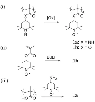
Such macromolecules can be synthesized from (i) oxidation or reduction of a precursor macromolecule, (ii) preparation and the subsequent polymerization of a radical monomer containing a vinyl group, and (iii) introduction of a radical unit to a macromolecular backbone through a polymer reaction. The preparation of poly(methacryloylamino- or 4-methacryloyloxy-2,2,6,6-tetramethylpiperidine-1-oxyl) 1 is shown as an example (Fig. 1.1). It is generally difficult to achieve a high yield in chemical oxidation reaction of the precursor macromolecule (here piperidine groups as a radical precursor)17
except for X O N O X O N H O O N O BuLi HO O N O NH2 n 1a:X = NH 1b:X = O n [Ox] (i) 1b (ii) n (iii) 1a
Fig. 1.1. Preparation procedures of poly(4-methacryloylamino- or
the recent report of almost quantitative conversion of poly(4-methacryloyloxyl-2,2,6,6-tetramethylpiperidine) to 1bvia the oxidation with m-chloroperbenzoic acid.18
1 could be prepared by the anionic polymerization of the corresponding monomer with butyllithium or phenylmagnesium bromide as the initiator, maintaining a high spin concentration.19-22
Polymer reaction of precursor macromolecules usually gave the desired polyradicals with reasonalbe yields.23,24
The studies concluded that they are chemically stable at ambient conditions and that an electron exchange interaction takes place between the pendant nitroxide radicals. They also suggested a through-space weak antiferromagnetic interaction between the pendant radicals. These polyradicals have also been investigated as redox resins and antioxidants.
In order to give a ferromagnetic character to these polyradicals, π-electrons would play a vital role. Since the first report of an organic macromolecular ferromagnet in 1986 by A. A. Ovchinnikov et al.,25
a π-conjugated backbone has been used to ferromagnetically connect radical species via the through-bond intramolecular exchange interaction. The design of a non-Kekulé and non-disjoint type molecule is a prerequisite for the ferromagnetic interaction or high-spin state in a π-conjugated polyradical.26,27
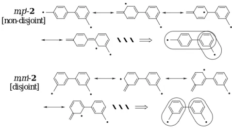
Taking into account the non-Kekulé type biphenyl biradicals 2, they are classified into two groups (Fig. 1.2). The effective overlap of the two nonbonding molecular orbitals (NBMOs) on the m,p'-isomer favors the parallel orientation of the two unpaired electrons according to Hund’s rule to stabilize the triplet ground state,
Fig. 1.2. Non-disjoint and disjoint type connectivities of biphenyl biradicals 2.
・・・ ・・・ m,p'-2 m,m'-2 [non-disjoint] [disjoint]
which is called a non-disjoint system. On the other hand, the complete separation of the two NBMOs on the m,m'-isomer results in a smaller exchange interaction between the two unpaired electrons, and consequently, the almost total degeneration of the triplet and singlet states, which is called the disjoint system.
π-Conjugated polyradicals precisely prepared according to the non-Kekulé and non-disjoint rules are expected to have a very high spin quantum number (S) in proportion to the degree of polymerization.28-31
A. Rajca synthesized poly(1,3-phenylenephenylmethine)s and extended it to the star-shaped decaradical 3 and dendritic pentadecaradical 4.32
These polyradicals displayed a strong through-bond ferromagnetic interaction between adjacent radicals at low temperature but relatively low S values, e.g., 3.5 for 4 with 15 radical sites. This is because a small number of radical defects or a failure in generation of a radical interrupts the π-conjugated pathway and consequently suppresses an increase of S value. In order to overcome this disadvantage, a calix[4]arene ring as a macrocyclic structure with two pathways for the exchange interaction was newly selected. The defect-insensitive macrocyclic
Ar Ar Ar Ar Ar Ar Ar Ar Ar Ar Ar Ar Ar Ar Ar Ar Ar Ar Ar Ar Ar Ar Ar Ar Ar Ar Ar Ar Ar X 3 4 5 Ar Ar Ar Ar Ar Ar Ar Ar Ar Ar n 6 Ar Ar Ar Ar Ar Ar Ar Ar Ar =
octaradical 5 and the ladder type tetradecaradical showed a high S value of 3.8 and 6.2, respectively, as expected.33,34
Polycondensation of the two tetrafunctionalized calix[4]arene subparts using the Negishi coupling reaction gave a polymacrocyclic network macromolecule. The corresponding polyradical 6 is designed with an alternating connectivity of the macrocyclic subpart (S = 2) and linker moiety (S = 1/2) in a non-Kekulé and non-disjoint fashion, which induces a high S value irrespective of either the ferromagnetic or antiferromagnetic coupling between the subpart and the linker moiety.35
For the soluble part of 6 with Mn > 10 5
, a striking increase of S > 40 was realized.36
Remarkably, the insoluble part of 6 exhibited an average S value of 5000 and behaved magnetically as insulating spin glasses and blocked superparamagnets at low temperature.37
This is the first example of the purely organic-derived magnetic macromolecule with magnetic anisotropy.
Another approach to obtain a very high-spin polyradical is a π-conjugated macromolecule pendantly bearing radical groups in a non-Kekulé and non-disjoint fashion. In contrast to Rajca’s polyradicals, which lack chemical stability at room temperature, the pendant-type polyradical has the advantages that a chemically stable radical species such as phenoxyl and nitroxide can be introduced as a pendant radical group and that it is insensitive to the radical defects because of a long distance interaction through the π-conjugated backbone to align even remote radicals.38-40
Poly(phenylenevinylene)-based polyradicals 7 and 8 were synthesized using the Heck reaction of bromostyrene derivatives.41-44
The backbone has a relatively high coplanarity and radicals can be delocalized over the entire molecule to effectively interact with each other. In addition, these polyradicals are stable enough to be handled even under air at room temperature. Although the S value for polynitroxide 8 with the spin concentration of 0.9 remained 1, polyphenoxyl 7 with the spin concentration of 0.7 displayed S = 2.5. The star-shaped polyradical 9 as a pseudo-two-dimensionally extension form of 7 demonstrated the cooperative ferromagnetic interaction between the 1,3,5-benzenetriyl core and three branch chains to give S = 3.5.45,46
Further development to achieve a more robust ferromagnetic interaction is based on the extension and coplanarity of the two-dimensional π-conjugated system. Polycondensation of the star-shaped hexamer 9 as a trifunctionalized subpart and 1,3-divinyl-4-phenoxylbenzene as a bifunctionalized subpart using the Pd/P catalyst yielded the starburst-shaped planar macromolecule with Mn = 3.2×10
4
.47
potential of the macromolecule indicated a highly extended π-conjugation beyond 9. The corresponding polyradical 10 with the spin concentration of 0.4 reached S = 5, which was definitely higher than that of 9.
A chemically stable radical species has also been introduced into the main chain of π-conjugated polyradicals. Ionic radicals or certain polarons were often employed as such radical species. D. A. Dougherty et al. synthesized 11 with Mn = 3.6×10
3
through Suzuki coupling reaction of 2,6-di-tert-butyl fuchsone moiety and m-phenylene coupler.48
The electrochemically generated poly(anionic radical) 11 showed S = 2 with the spin concentration of 0.6, which provided the good correlation between spin concentration and S value. Cationic radicals of triarylamine or p-phenylenediamine (aminium cationic radicals) are one of the chemically persistent radicals, and their spin density is known to be delocalized into the aromatic groups. J. F. Hartwig et al. applied the palladium-catalyzed amination reaction to the synthesis of linear macromolecules containing the aminium cationic radicals.49-51
12 and 13 have a n 8 7 Br Br Br O O O O O O O O O n l m 9 O O O O O O O n 10 O n N O
regiodefined primary structure with Mn = 2.2×10 4
and 3.5×10⁴
, respectively, which indicated the possibility of a high-spin ground state. R. J. Bushby et al. synthesized the two-dimensional network structure of the triarylamine-based macromolecule with Mw = 3.4×10
4
via the Suzuki coupling reaction.52-54
Exposure of a thin film of the precursor macromolecule to SbCl5 vapor gave the corresponding poly(aminium cationic
radical) 14, which displayed S = 4 with the spin concentration of 0.6. S. C. Blackstock et al. reported the poly(arylamine) dendrimer 15, which shows the unique redox behavior with a gradient.55
The interior three p-phenylenediamine moieties of 15 are classified as a quartet structure judging from the previous report,56,57
and 15 itself corresponds to a precursor of the high-spin poly(aminium cationic radical). All of the polyradicals mentioned here have more or less difficulty in optimizing radical generation to form the largest spin cluster. Therefore, the macrocyclic or pendant type approach is certainly essential to avoid the radical defect in a π-conjugated high-spin polyradical. Furthermore, as revealed by the successful performance of Rajca’s
N OCH3 n 11 N N OC4H9 OC4H9 n 12 C14H29 OC4H9 N C4H9O C4H9O N OC4H9 C4H9O C4H9O C14H29 C14H29 14 O C14H29 n 13 N N N N N N N N N N N N R R R R R R R R R R R R R R R R R R 15 R = -OCH3
polyradical, the dimensionally extended network polyradical is an effective approach to achieve a magnetic macromolecule with very high S values. The employment of stable radical species as a spin source in the network polyradicals should become the next trend toward a macromolecular ferromagnet effectively working at room temperature.
1.3
Magnetic force microscopy
Magnetic force microscopy (MFM) has emerged as a type of non-contact operation mode of scanning probe microscopy.58-64
The advantages for its magnetic imaging include a fairly high resolution on a 10 nm scale and simple operation under ambient conditions in most cases without any special sample preparation, which made MFM a standard analytical tool and has lead to rapid progress in MFM applications to material science and data storage. On the other hand, quantitative interpretation of MFM images still remains a challenging topic and many active studies have been undertaken in this area.
MFM is, from an instrumental point of view, very closely related to atomic force microscopy (AFM) except for being equipped with a ferromagnetic probe. The microscope’s cantilever equipped with the ferromagnetic probe achieves a local magnetostatic interaction between the probe and the stray micromagnetic field from a sample on the substrate. The probe is assumed to effectively behave as a point dipole, which provides the basic idea of the magnetic force acting on the probe: If the effective magnetic moment of the probe is oriented along the vertical direction without inversion induced by the magnetic field of a sample and the magnetic distribution of a sample is not perturbed by the probe’s dipole moment, the MFM response is proportional to the second differential with respect to the vertical component of the stray field originating from a sample at the probe location. The quantitative analysis of the magnetic response is generally difficult, because there is a problem in determining properties of the probe such as spring constant and magnetic moment, which are the important variables in the magnetic force calculation. Nevertheless, many attempts have been made to calibrate an MFM probe and calculate its magnetic moment, and some of them were successful under certain conditions.58,65
They revealed that an MFM image could be reasonably simulated using the parameters. Magnetic
dissipation microscopy, which monitors the drive power necessary to keep a constant amplitude of cantilever oscillation during MFM imaging, also offered a promising prospect for quantitatively evaluating MFM probe performance.66,67
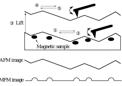
Separation of the surface topography and magnetic contrast is a practically important issue especially when scanning a rough surface. The Lift Mode technique68
developed by Digital Instruments, Inc., is efficient for the complete image acquisition. The first scan is in the tapping mode to recognize the surface or the shape of the sample, that is, AFM with the ferromagnetic probe. After lifting the probe to a certain height which can be selected as desired upon tuning, the second scan along the known trajectory above the same area uses the non-contact mode, and the magnetic gradient of the sample is detected by measuring the deflection of the cantilever equipped with the ferromagnetic probe in the static mode of the MFM operation (Fig. 1.3). During the second scan, the van der Waals force between the probe and the sample almost disappears and the probe mainly responds to magnetic forces. The lateral resolution of the MFM image largely depends on the probe-sample distance and the probe geometry. Close proximity of the probe to the sample surface and sharpening of the probe apex will bring about an improved resolution. It is generally said that the limitation of the lateral resolution is almost identical to the probe-sample distance when a commercial probe is used.
Fig. 1.3. Schematics of magnetic force microscopy operation.
① ② ③Lift ④ ⑤ AFM image MFM image Magnetic sample
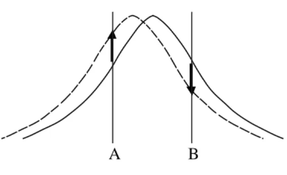
Actual MFM contrasts are recorded as amplitude, phase, or frequency shifts of the cantilever oscillation when a Nanoscope IIIa with a MultiMode AFM/MFM microscope (Digital Instruments, Inc.) is used. For amplitude detection, the drive frequency of the cantilever is set slightly higher or lower than its resonance frequency and variations in the oscillation amplitude are tracked while raster-scanning across the sample surface. If an attractive force between the probe and the sample is detected, the resonance curve of the cantilever shifts toward a lower frequency. Consequently, the amplitude at the fixed drive frequency lower than the resonance frequency increases, but it oppositely decreases at the higher drive frequency (Fig. 1.4). Since topographic information never provides inversion of the image, this method can be useful in verifying that the obtained MFM image is surely derived from the magnetic information. Phase detection, which measures the phase lag of the cantilever oscillation relative to the piezo drive, provides images with a better signal-to-noise ratio and less contamination of topographic data compared to amplitude detection. Frequency modulation detection, which directly tracks frequency variations by keeping the cantilever’s phase lag at 90 degrees, also has features of an improved signal-to-noise ratio and independence of the cantilever’s quality factor. These are generally superior methods to amplitude detection for more extensive and quantitative MFM images.
A B
Fig. 1.4. Shift of resonance curve in amplitude detection. The initial curve (solid line) is
shifted to lower frequency (dotted line) by the attraction between probe and sample. If the drive frequency is set at point A, which is lower than the resonance frequency, an amplitude shift is positive. On the contrary, if drive frequency is set at point B, the amplitude shift is negative.
MFM can provide detailed information on a magnetic structure with a nanometer size, unlike other magnetic measurements such as SQUID and ESR that evaluate the magnetic property of a sample as a bulk. Accordingly, magnetically responsible nanoparticles or nanodots are very suitable for its motif. In actual measurements, an MFM probe coated with a ferromagnetic alloy is used after being magnetized in the direction perpendicular to the sample surface. It should be noted here that the MFM image must be interpreted carefully if the nano-sized sample has a weak magnetic moment relative to the ferromagnetic probe. The magnetic field from the MFM probe might perturb or reverse the sample magnetization upon measurement. In such a case, the application of an external magnetic field should be a good approach. Since a strong external magnetic field brings about a motion or pinning of domain walls, it is often used for investigating the dynamics of a magnetic sample.69-72
On the other hand, the homogeneous magnetic field applied perpendicular to the sample surface is not detected as an MFM response to some extent. Therefore, if the external magnetic field will induce the sufficient sample magnetization not to be altered by the ferromagnetic probe, a reliable magnetic image will be attained. Another approach to gain the proper interpretation of the MFM image is to exchange the probe for a different one with a smaller (or much larger) magnetic moment than that of the sample.73
One can obtain more information on the magnetic origin from changes of the magnetic contrast. These methods enable the easy detection of a very weak magnetic moment, which will lead to the widespread applications of MFM in the future technology.
References
1.S. Sun, C. B. Murray, D. Weller, L. Folks, and A. Moser, Science, 287, 1989 (2000). 2. O. Pietzsch, A. Kubetzka, M. Bode, and R. Wiesendanger, Science, 292, 2053 (2001). 3. L. Krusin-Elbaum, T. Shibauchi, B. Argyle, L. Gignac, and D. Weller, Nature, 410,
444 (2001).
4. P. Gambardella, A. Dallmeyer, K. Maiti, M. C. Malagoli, W. Eberhardt, K. Kern, and C. Carbone, Nature, 416, 301 (2002).
5. P. M. Lahti, “Magnetic Properties of Organic Materials,” Marcel Dekker, New York, 1999.
6. K. Itoh and M. Kinoshita, “Molecular Magnetism-New Magnetic Materials,” Kodansha and Gordon and Breach Science Publishers, Tokyo and Amsterdam, 2000. 7.M. R. Freeman and B. C. Choi, Science, 294, 1484 (2001).
8. D. Braun, in N. M. Bikales (ed.), “Encyclopedia of polymer science and technology, 15,” Interscience, New York, 1971, p. 429, and references therein.
9. Y. Kurusu, H. Yoshida, and M. Okawara, Tetrahedron Lett., 37, 3595 (1967).
10. T. Kurosaki, O. Takahashi, and M. Okawara, J. Polym. Sci., Polym. Chem. Ed., 12, 1407 (1974).
11. T. Miyazawa, T. Endo, and M. Okawara, , J. Polym. Sci., Polym. Chem. Ed., 23, 1527 (1985).
12. Y. Miura, M. Kinoshita, and M. Imoto, Makromol. Chem., 146, 69 (1971). 13. Y. Miura, M. Kinoshita, and M. Imoto, Makromol. Chem., 157, 51 (1972). 14. F. E. Karrer, Makromol. Chem., 181, 595 (1980).
15. M. Kamachi, H. Enomoto, M. Shibasaka, W. Mori, and M. Kishita, Polym. J., 18, 439 (1986).
16. R. B. Upasani, L. Y. Chiang, and D. P. Goshorn, Mater. Res. Soc. Symp. Proc., 173, 77 (1990).
17.T. Kurosaki, K. Y. Lee, and M. Okawara, J. Polym. Sci., Polym. Chem. Ed., 10, 3295 (1972).
18.K. Nakahara, S. Iwasa, M. Satoh, Y. Morioka, J. Iriyama, M. Suguro, and E. Hasegawa, Chem. Phys. Lett., 359, 351 (2002).
19.O. H. Griffith, J. F. W. Keana, S. Rottschaefer, and T. A. Warlick, J. Am. Chem. Soc.,
89, 5072 (1967).
20. M. Kamachi, M. Tamaki, Y. Morishima, S. Nozakura, W. Mori, and M. Kishita, Polym. J., 14, 363 (1982).
21. F. MacCorquodale, J. A. Crayston, J. C. Walton, and D. J. Worsfold, Tetrahedron Lett.,
31, 771 (1990).
22. J. Allgaier and H. Finkelmann, Makromol. Chem., Rapid Commun., 14, 267 (1993). 23. P. Ferruti, D. Gill, M. P. Klein, H. H. Wang, G. Entine, and M. Calvin, J. Am. Chem.
Soc., 92, 3704 (1970).
24. T. Osa, U. Akiba, I. Segawa, and J. M. Bobbit, Chem. Lett., 1988, 1423.
25. U. V. Korshak, T. V. Madvedeva, A. A. Ovchinnikov, and V. N. Spector, Nature, 326, 370 (1987).
26. W. T. Borden and E. R. Davidson, J. Am. Chem. Soc., 99, 4587 (1977). 27. H. Iwamura, Adv. Phys. Org. Chem., 26, 179 (1990).
28. H. Iwamura and N. Koga, Acc. Chem. Res., 26, 346 (1993). 29. A. Rajca, Chem. Rev., 94, 871 (1994).
30. J. S. Miller and A. J. Epstein, Angew. Chem. Int. Ed. Engl., 33, 385 (1994). 31. J. A. Crayston, J. N. Devine, and J. C. Walton, Tetrahedron, 56, 7829 (2000). 32.A. Rajca and S. Utamapanya, J. Am. Chem. Soc., 115, 10688 (1993).
33. A. Rajca, S. Rajca, and S. R. Desai, J. Am. Chem. Soc., 117, 806 (1995). 34. A. Rajca, K. Lu, and S. Rajca, J. Am. Chem. Soc., 119, 10335 (1997). 35. S. Rajca and A. Rajca, J. Solid State Chem., 159, 460 (2001).
36.A. Rajca, S. Rajca, and J. Wongsriratanakul, J. Am. Chem. Soc., 121, 6308 (1999). 37. A. Rajca, J. Wongsriratanakul, and S. Rajca, Science, 294, 1503 (2001).
38.H. Nishide, Adv. Mater., 7, 937 (1995).
39. M. Miyasaka, T. Yamazaki, E, Tsuchida, and H. Nishide, Macromolecules, 33, 8211 (2000).
40. Y.-J. Pu, M. Soma, J. Kido, and H. Nishide, J. Polym. Sci. Part A: Polym. Chem., 38, 4119 (2000).
41. H. Nishide, T. Kaneko, T. Nii, K. Katoh, E. Tsuchida, and K. Yamaguchi, J. Am. Chem. Soc., 117, 548 (1995).
42. H. Nishide, T. Kaneko, T. Nii, K. Katoh, E. Tsuchida, and P. M. Lahti, J. Am. Chem. Soc., 118, 9695 (1996).
43. T. Kaneko, S. Toriu, Y. Kuzumaki, H. Nishide, and E. Tsuchida, Chem. Lett., 1994, 2135.
44. H. Nishide, T. Kaneko, S. Toriu, Y. Kuzumaki, and E. Tsuchida, Bull. Chem. Soc. Jpn.,
69, 499 (1996).
45. H. Nishide, M. Miyasaka, and E. Tsuchida, Angew. Chem. Int. Ed. Engl., 37, 2400 (1998).
46. H. Nishide, M. Miyasaka, and E. Tsuchida, J. Org. Chem., 63, 7399 (1998).
47.H. Nishide, T. Ozawa, M. Miyasaka, and E. Tsuchida, J. Am. Chem. Soc., 123, 5942 (2001).
48. K. K. Anderson and D. A. Dougherty, Adv. Mater., 10, 688 (1998). 49. F. E. Goodson and J. F. Hartwig, Macromolecules, 31, 1700 (1998). 50. J. Louie and J. F. Hartwig, Macromolecules, 31, 6737 (1998).
51. F. E. Goodson, S. I. Hauck, and J. F. Hartwig, J. Am. Chem. Soc., 121, 7527 (1999). 52. R. J. Bushby, D. R. McGill, K. M. Ng, and N. Taylor, J. Mater. Chem., 7, 2343
(1997).
53. R. J. Bushby and D. Gooding, J. Chem. Soc., Perkin Trans. 2, 1998, 1069.
54. R. J. Bushby, D. Gooding, and M. E. Vale, Phil. Trans. R. Soc. Lond. A, 357, 2939 (1999).
55. T. D. Selby and S. C. Blackstock, J. Am. Chem. Soc., 120, 12155 (1998).
56. K. R. Stickley, T. D. Selby, and S. C. Blackstock, J. Org. Chem., 62, 448 (1997). 57. M. M. Wienk and R. A. J. Janssen, J. Am. Chem. Soc., 119, 4492 (1997).
58. K. Babcock, M. Dugas, S. Manalis, and V. Elings, Mater. Res. Soc. Symp. Proc., 355, 311 (1995).
59. L. A. Bottomley, Anal. Chem., 70, 425R (1998).
60. S. Porthun, L. Abelmann, and C. Lodder, J. Magn. Magn. Mater., 182, 238 (1998). 61. L. Folks and R. C. Woodward, J. Magn. Magn. Mater., 190, 28 (1998).
62. U. Hartmann, Ann. Rev. Mater. Sci., 29. 53 (1999).
63. R. Proksch, Curr. Opin. Solid State Mater. Sci., 4, 231 (1999). 64. I. V. Yaminsky and A. M. Tishin, Russ. Chem. Rev., 68, 165 (1999).
65. H. J. Hug, B. Stiefel, P. J. A. van Schendel, A. Moser, R. Hofer, S. Martin, H.-J. Güntherodt, S. Porthun, L. Abelmann, J. C. Lodder, G. Bochi, and R. C. O’Handley, J. Appl. Phys., 83, 5609 (1998).
66. Y. Liu and P. Grütter, J. Appl. Phys., 83, 7333 (1998).
67. R. Proksch, K. Babcock, and J. Cleveland, Appl. Phys. Lett., 74, 419 (1999).
68. V. Elings, J. Gurley, US Patent 5 308 974, Digital Instruments, Santa Barbara, CA, May 3, 1994.
69. R. Proksch, E. Runge, P. K. Hansma, S. Foss, and B. Walsh, J. Appl. Phys., 78, 3303 (1995).
70. J. Shi, S. Gider, K. Babcock, and D. D. Awschalom, Science, 271, 937 (1996).
71. K. L. Babcock, L. Folks, R. Street, R. C. Woodward, and D. L. Bradbury, J. Appl. Phys., 81, 4438 (1997).
72. R. D. Gomez, T. V. Luu, A. O. Pak, I. D. Mayergoyz, K. J. Kirk, and J. N. Chapman, J. Appl. Phys., 85, 4598 (1999).
73. L. Folks, R. Street, R. C. Woodward, and K. Babcock, J. Magn. Magn. Mater., 159, 109 (1996).
Preparation of Nanometer-Sized Polyradical
Particles and their Single Molecular-Based
Magnetic Images
2.1 Introduction
2.2 Experimental section
2.3 Preparation of nitroxide-particle through emulsifier-free emulsion polymerization
2.4 Anionic dispersion polymerization of nitroxide monomer 2.5 Magnetic response of polyradical particles
2.1 Introduction
In recent years, magnetic dots consisting of metals or metal oxides of 10−100 nanometer (nm) sizes have been significantly investigated because of their potential use as future high-density magnetic recording media.1-3
However, there has been no report, to our knowledge, on a magnetically responsible “dot” composed of purely-organic derived materials. Among the nm-sized materials, organic macromolecules that possess a single molecular-based size in the nanometer range have received considerable attention, because they are prepared by conventional macromolecular chemistry and their molecular structure is designable.4
In particular, the preparation of organic macromolecular particles with a size from 10 nm to µm has been established and their applications have been widely investigated.5
The emulsion and dispersion polymerizations are useful for preparing macromolecular particles in that size range. One of the ways to make non-diamagnetic and paramagnetic organic macromolecules is the accumulation of stable open shell molecules by preparing the macromolecule bearing stable radicals pendantly or integrating them into the main chain.6,7
They are often called polyradicals and have been studied as a redox resin and an antioxidant. Nevertheless, no attempt has been made using a nm-sized polyradical particle composed of persistent organic radical species up to now (the π-conjugated but non-Kekulé-type and high-spin polyradicals with a nm-size has already been reported, but they were not persistent under air at room temperature8
). We selected, in this chapter, the 2,2,6,6-tetramethylpiperidine-1-oxyl (TEMPO) radical as a persistent radical, and describe the preparation of nm-sized and single molecular-based particles bearing TEMPO radicals and the detection of a very weak magnetic signal of the polyradical particles by magnetic force microscopy (MFM) as a dot image.
2.2 Experimental section
2.2.1 MaterialsPolystyrene-block-polybutadiene was purchased from Aldrich and was purified by repeated reprecipitation from chloroform into methanol (30 wt% polystyrene content, Mn = 1.7×10
5
under reduced pressure before use. The potassium persulfate was recrystallized from water. The solvents for the anionic dispersion polymerization were carefully distilled under nitrogen. The solvents and triethylamine were purified in the usual manner. The other reagents were used as received.
2.2.2 Preparations
An emulsifier-free emulsion polymerization was carried out in a 300 ml round-bottom flask equipped with a reflex condenser, a nitrogen inlet, and an extendable bladed agitator. The ratio of monomers to water was held constant at 6/94 (g/g). The monomer feed composition, methyl methacrylate / methacrylic acid / methylenebisacrylamide, was changed from 94/1/5 to 65/30/5 mol%. The weighed monomers and water, e.g., 4.0 g of methyl methacrylate, 1.55 g of methacrylic acid, and 0.45 g of methylenebisacrylamide in 89 ml of water, were put into the flask and nitrogen was bubbled into the solution for 30 min at 80o
C with stirring at 300 rpm. An aqueous solution of 0.022 g potassium persulfate (5 ml) was added to initiate the polymerization. The polymerization was continued for 4 h at 80o
C and then allowed to cool to room temperature. The produced macromolecular particles were purified with water by three centrifugation separations at 12000 rpm for 20 min, and dried in vacuo at 100o
C for 24 h. A 0.1 g sample of the particles was then dispersed into 10 ml of thionyl chloride and heated to 70o
C for 24 h. After thoroughly removing the thionyl chloride, 0.1 g of 4-amino-2,2,6,6-tetramethylpiperidine-1-oxyl and 3 g of triethylamine in 5 ml of dichloromethane were added and stirred at room temperature for 24 h. The polyradical particle was isolated by repeated decantation, washing with dichloromethane, and drying in vacuo.
The anionic dispersion polymerization of 4-methacryloyloxy-2,2,6,6-tetramethylpiperidine-1-oxyl (MOTMP) was carried out in a Schlenk tube under an argon atmosphere. A typical procedure is as follows. In the tube were directly placed 5 ml of anhydrous hexane from the distillation apparatus, 0.2 g of MOTMP, and 0.02 g of polystyrene-block-polybutadiene, and the mixture was stirred until dissolved. A 0.2 ml hexane solution of sec-butyllithium (1.0 M) was added dropwise with a dried syringe at room temperature. After stirring for 30 min, the reaction was terminated with methanol.
4-methacryloyloxy-2,2,6,6-tetramethylpiperidine-1-oxyl), were prepared according to the literature.9,10
The former was obtained by the chemical oxidation of the precursor macromolecule with hydrogen peroxide in the presence of ethylenediaminetetraacetic acid and sodium tungstate (0.22 spin unit-1
; 0.91 mmol g-1
, [η] = 1.7 in acetone at 20o
C). The latter was obtained by the anionic polymerization of MOTMP with sec-butyllithium in THF at room temperature (0.81 spin unit-1
; 3.3 mmol g-1
, Mn = 2.3×10 4
).
The polystyrene-block-poly(methyl methacrylate) was prepared by the living radical polymerization of methyl methacrylate using the chlorine atom end-capped polystyrene and CuCl and 2,2'-bipyridine as an initiator at 130o
C (25 wt% polystyrene content, Mn = 9.6×10
4 ). 11
2.2.3 Measurements
Atomic force microscopy (AFM) and MFM measurements were performed using a Nanoscope IIIa multimode AFM/MFM microscope (Digital Instruments, Inc.). A drop of dilute dichloromethane solution or dispersion of the polyradical was transferred onto a highly oriented pyrolytic graphite, and the solvent was carefully blotted off by air-drying. Tapping mode AFM using a Si probe (type TESP) was applied to estimation of the horizontal distance of particles. The size and the shape of probe are known to affect AFM images,12
therefore, the same probe was used for all measurements. The MFM images were presented by an amplitude or phase shift acquired with the Lift Mode technique. The scan lift height was controlled by the scanning parameters, assuming that the sensitivity of the cantilever was 0.03 V nm-1
. A commercially available MFM probe (type MESP) coated with a ferromagnetic CoCr alloy possessing a magnetic moment of 1×10-13
emu was used, which was magnetized in the direction perpendicular to the sample surface.
The light scattering measurement was performed with a Coulter N4SD sub-micron particle analyzer. The scanning electron microscope used was a S2500CX (Hitachi) for observing the polyradical particle. The molecular weight of the macromolecules was estimated by GPC (polystyrene gel column, eluent THF, polystyrene calibration).
2.3 Preparation of nitroxide-particle through emulsifier-free
emulsion polymerization
It is well known that nm- or sub-µm-sized and monodispersed macromolecular particles are obtained by a dispersion and emulsion polymerization. However, the obtained particles are covered with a stabilizer and an emulsifier that often results in a low yield in the following chemical modification of the particles. We used, in this study, an emulsifier-free emulsion terpolymerization of methacrylic acid, methyl methacrylate, and methylenebisacrylamide to obtain the particles. The feed composition of the methacrylic acid (1−30 %), methyl methacrylate as an oil-phase formation agent (94−65 %), and methylenebisacrylamide as a bifunctional crosslinker (5 %) through the emulsifier-free emulsion polymerization was first examined to obtain the poly(methacrylic acid) particle with a desirable size and applicable to the following reactions to introduce the TEMPO moiety. The more methacrylic acid was subjected to the polymerization, the more carboxyl groups were introduced into the particle, and a stable dispersion was maintained up to 30 % of the methacrylic acid content. Next the carboxyl function of the particle was treated with an excess amount of thionyl chloride to yield the acid chloride, followed by 4-amino-2,2,6,6-tetramethylpiperidine-1-oxyl in dichloromethane solution in the presence of triethylamine. The introduction of TEMPO groups into the particle and its amount were confirmed by elemental analysis. The determined TEMPO amount was ca. 1.4 times larger than that from SQUID measurements shown below (e.g., 1.5 mmol g-1
from elemental analysis corresponded to 1.1 mmol g-1
from magnetic measurement).
Light scattering measurement on the particle dispersion in dichloromethane indicated, for example, an average diameter of 400 nm and a narrow distribution (±60 nm) for the TEMPO sample derived from the particle prepared by the polymerization of
CH2CH C O NH CH2 NH C O CH2CH CH3 CH2C C O NH CH2C CH3 C O OCH3 N O l m n
methacrylic acid (20 %), methyl methacrylate (75 %), and methylenebisacrylamide (5%). A dilute dichloromethane dispersion of the particle was transferred to a highly oriented pyrolytic graphite surface, and was subjected to AFM. An approximate 280 nm diameter was estimated for the polyradical particle. AFM gave a slightly smaller diameter than that by the light scattering, probably because of the lack of swelling or a solvent-free sample state for the AFM measurement.
The spin concentration and persistency of the polyradical particle were estimated by SQUID measurements. The magnetic susceptibility data for all samples obeyed the Curie-Weiss law with a small Weiss constant of less than −1 K. For four kinds of polyradical particles with almost the same diameter of ca. 300 nm, the spin concentrations (mmol g-1
) of 1.1, 0.85, 0.60, and 0.17 were estimated from the slope of the plots in each case. These values correspond to the maximum yield of ca. 50 % for the methacrylic acid residues in the particle. All polyradical particles prepared were fully stable at room temperature under atmospheric conditions for at least 6 months.
2.4 Anionic dispersion polymerization of nitroxide monomer
A direct one-step preparation of the desired polyradical particle was tried by the anionic dispersion polymerization of the nitroxide monomer, 4-methacryloyloxy-2,2,6,6-tetramethylpiperidine-1-oxyl (MOTMP). It has been reported that both the radical and cationic polymerizations of a nitroxide-bearing vinyl monomer did not proceed but the anionic polymerization of the nitroxide monomer, e.g., MOTMP, directly gave a nitroxide polyradical.10,13,14
MOTMP was anionically polymerized in hexane with sec-butyllithium as an initiator in the presence of polystyrene-block-polybutadiene as the stabilizer. Immediately after the addition of the initiator, there appeared a light orange turbidity, which indicated the progress of the polymerization and the particle formation. GPC measurement of the resulting macromolecule dissolved in THF indicated the polyradical formation with a molecular weight of Mn =
3.2×10³
. Its spin concentration estimated from the SQUID measurement was 2.0 mmol g-1
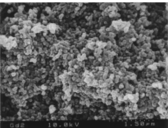
. This spin concentration was twice that of the highest one for the polyradical particle prepared by the polymer reaction. A scanning electron micrograph of the product revealed the formation of a relatively monodispersed particle with ca. 100 nm
diameter and their aggregation. Thus it was concluded that the anionic dispersion polymerization of MOTMP was useful for preparing the corresponding polyradical particle with a high spin concentration in one step. However, the AFM images gave only the aggregate of particles and it was difficult to obtain an image of the dispersed single particle even by replacing the solvent species of the particle suspension and a stabilizer (e.g., polystyrene-block-poly(methyl methacrylate)) in the anionic dispersion polymerization. Therefore, this polyradical particle could not be subjected to the subsequent MFM measurement.
2.5 Magnetic response of polyradical particles
Magnetic force microscopy (MFM) is a scanning probe technique and a powerful tool for sub-µm magnetic imaging.15,16
The microscope’s cantilever equipped with the ferromagnetic probe achieves a local magnetostatic interaction between the probe and a magnetic sample on the substrate or the sample surface. In this study, our sample is paramagnetic and has a weak magnetic moment relative to ferromagnetic materials at which the MFM has generally aimed and been utilized, therefore, we set the sample holder on a powerful magnet to induce the magnetic vector of the sample. The magnet consists of a NdFeB alloy, with which a multimode SPM scanner AS-130 (J) for the Nanoscope IIIa is equipped. The effective external magnetic field at the sample position through a stainless holder was estimated to be ca. 80 G using a Gaussmeter, which seemed to be sufficient to affect the paramagnetic sample in this study. The polyradical sample would sense an adequate external magnetic field, and the ferromagnetic MFM probe would respond to a change in the magnetic permeability at the position of the paramagnetic polyradical sample.
CH3 CH2C C O O N O n MOTMP
Dilute dichloromethane solution of the linear polyradical, poly(4-methacryloylamino- or 4-methacryloyloxy-2,2,6,6-tetramethylpiperidine-1-oxyl) as a control, was transferred to a graphite surface and subjected to AFM followed by MFM. Both images were obtained at ambient conditions or under air at room temperature. The MFM image appeared exactly on the molecular positions detected by the AFM image. However, the disadvantage of the linear polyradical was unsettled images, which strongly depended on the surface deposition process or evaporation process of the solvent, solvent species, and so on. These often include ellipse images with a broad distribution of diameter consisting of the aggregation of many molecules, taking into account the molecular weight of the macromolecule.
This result was in contrast to the polyradical particle with a controlled and monodispersed diameter. A clear particle or dot shape is observed for the polyradical particle, which was not affected by the deposition process on the graphite substrate. The AFM gave 102
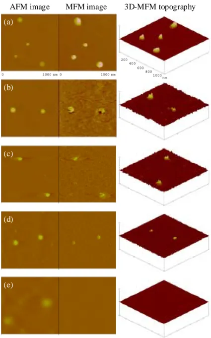
nm-sized dot images of the single polyradical particle (Fig. 2.1). The following MFM clearly indicated magnetic gradient responses exactly on the same single polyradical particle positions. The three-dimensional representation of the MFM topography demonstrates “holes” ascribed to the polyradical particle. By switching the drive frequency of the cantilever from higher to lower against the resonance frequency, the MFM image was inverted, which supported the magnetic response of the observed images and denied a noise image caused by surface information in the AFM.
Figure 2.1 shows the effect of the radical or spin concentration of the particle on the MFM image. For all measurements, the same apparatus and the same cantilever were used, and the scan lift height or the distance between the probe and the sample surface was maintained at 30 nm. The intensity of the MFM image, that is, the magnitude of magnetic gradient decreased with a decrease in spin concentration of the polyradical particle. The magnetic gradient response was not observed for the particles without radical, which indicated that the contribution of diamagnetism to the probe at a certain height was almost the same in this series of study. The MFM vertical scale could be, in principle, represented by a force which is related to the detailed magnetic properties of the probe such as the absolute value of the effective magnetic moment and its hysteresis loop, the spring constant of the cantilever upon measurement, and the scan lift height, but it was given as an arbitrary unit here.
3D-MFM topography AFM image MFM image
200 400 600 800 1000 nm 0 1000 nm 0 1000 nm (a) (b) (c) (d) (e)
Fig. 2.1. Effect of the spin concentration of the polyradical particles. (left) AFM,
(middle) MFM images obtained by detecting phase shifts in the cantilever oscillation caused by attractive forces acting on the ferromagnetic probe, and (right) three-dimensional representations of the MFM images of the polyradical particles with different spin concentrations (mmol g-1) (a) 1.1, (b) 0.85, (c) 0.60, (d) 0.17, and (e) 0.
The MFM of the particle with a low spin concentration of 0.17 mmol g-1
gave an interesting hollow dot image when the scan lift height was adjusted to 35 nm (Fig. 2.2). On this particle sample, the radical group was introduced by the polymer reaction and the radicals are homogeneously distributed only over the particle surface where the reaction initially occurred but not inside. The magnetic response as the deflection of the cantilever is based on the second differential of the magnetic field in the vertical direction. A strong magnetic gradient is detected on the perimeter of the particle but is very weak in the interior. This consideration could explain such a hollow dot image.
References
1. F. J. Himpsel, J. E. Ortega, G. J. Mankey, and R. F. Willis, Adv. Phys., 47, 511 (1998). 2. J.-Q. Wang, L. M. Malkinski, Y. Hao, C. A. Ross, J. A. Wiemann, and J. O’Connor,
Mater. Sci. Eng., B, 76, 1 (2000).
3. J. Lohau, S. Kirsch, A. Carl, and E. F. Wassermann, Appl. Phys. Lett., 76, 3094
Fig. 2.2. MFM hollow dot image of the polyradical particle with low spin concentration.
(a) AFM, (b) MFM, and (c) cross sectional view of the MFM image.
0 10 00 nm 0 10 00 nm
0 40 0 800 nm
(a) (b)
(2000).
4. D. A. Tomalia, H. Baker, J. Dewald, M. Hall, G. Kallos, S. Martin, J. Roeck, and P. Smith, Polym. J., 17, 117 (1985).
5. H. Kawaguchi, Prog. Polym. Sci., 25, 1171 (2000).
6. P. M. Lahti, “Magnetic Properties of Organic Materials,” Marcel Dekker, New York, 1999.
7. K. Ito and M. Kinoshita, “Molecular Magnetism – New Magnetic Materials,” Kodansha and Gordon and Breach Science Publishers, Tokyo and Amsterdam, 2000. 8. H. Nishide, T. Ozawa, M. Miyasaka, and E. Tsuchida, J. Am. Chem. Soc., 123, 5942
(2001).
9. T. Kurosaki, K. W. Lee, and M. Okawara, J. Polym. Sci., Polym. Chem. Ed., 10, 3295 (1972).
10. M. Kamachi, M. Tamaki, Y. Morishima, S. Nozakura, W. Mori, and M. Kishita, Polym. J., 14, 363 (1982).
11. J.-S. Wang and K. Matyjaszewski, J. Am. Chem. Soc., 117, 5614 (1995). 12. S. J. Eppell, F. R. Zypman, and R. E. Marchant, Langmuir, 9, 2281 (1993).
13. O. H. Griffith, J. F. Keana, S. Rottschaefer, and T. A. Warlick, J. Am. Chem. Soc., 89, 5072 (1967).
14. J. Allgaier and H. Finkelmann, Makromol. Chem., Rapid Commun., 14, 267 (1993). 15. L. A. Bottomley, Anal. Chem., 70, 425R (1998).
Synthesis of Stable Poly(acyl nitroxide)
3.1 Introduction
3.2 Experimental section
3.3 Synthesis of poly(acyl nitroxide) 3.4 Redox behavior of acyl nitroxide References
3.1 Introduction
A variety of macromolecules containing stable nitroxide radicals have been investigated as new magnetic materials.1-7
In particular, attempts aimed at a ferromagnetic macromolecule require a high spin concentration (the number of unpaired electrons in unit weight) in the macromolecule, because ferromagnetism arises from the cooperative interaction of a large number of unpaired electrons. Thus far, an increase of the yield in radical generation and radical attachment reactions with a precursor macromolecule and polymerization of a radical monomer without a side reaction have been mainly considered. From an intrinsic viewpoint, a new approach to minimize the molecular weight per radical unit should be proposed in order to increase the spin concentration of polynitroxide.
The nitroxide radical is well known as one of the most stable radicals.8-10
Although its reactivity generally increases by substituting the nitrogen atom with electron-withdrawing groups, many types of such stable nitroxides have been reported. For example, Fremy’s radical could become commercially available irrespective of the substitution of two sulfonate groups. Acyl nitroxides, both sides of which are effectively protected with tert-carbon atoms, also show enough chemical stability to be handled at room temperature.11,12
These examples indicate that a stable polynitroxide with a potentially high spin concentration is possible by replacing a bulky structure such as conventional piperidine ring in 2,2,6,6-tetramethylpiperidine-1-oxyl (TEMPO) with a compact carbonyl or tert-butyl group. If useless atoms without a direct contribution to the radical stability are removed, the ideal low molecular structure having an unpaired electron would be formed.
Nitroxide polyradicals, e.g., TEMPO macromolecules, have also been investigated as an N-oxy-mediated oxidizing agent of alcohols and amines.13,14
The redox between the nitroxide and oxoammonium salt, that is, the p-type redox reaction of a nitroxide is fully reversible through the catalytic cycle. On the other hand, there has been no report, to our knowledge, on the stable n-type redox system of a nitroxide. The nitroxide with an electron-withdrawing substituent is expected to have a high electron affinity as compared with TEMPO, which will result in an easy reduction or anodically shift of the overall redox potential. A search for the electronic structure of such a novel molecule is a very intriguing subject.
In this chapter, the N-acyl-N-tert-butylnitroxide was selected as the radical group with a high spin concentration. The synthetic process of the macromolecule pendantly bearing the acyl nitroxides, poly(N-tert-butyl-N-methacryloylnitroxide) 1, and the redox bahavior of the corresponding monoradical, N-tert-butyl-N-pivaloylnitroxide, are described.
3.2 Experimental section
3.2.1 MaterialsN-tert-Butylmethacrylamide was prepared by the reaction of tert-butylamine and methacryloyl chloride. Yield 60 %. N-tert-Butylhydroxylamine hydrochloride was treated with aqueous potassium hydroxide solution to yield the desalted compound. Solvents, pyridine, and triethylamine were purified in the usual manners. The other reagents were used as received.
3.2.2 Synthetic procedure
Poly(butylmethacrylamide) 2. A benzene solution (3 ml) of N-tert-butylmethacrylamide (0.50 g, 3.5 mmol) was stirred at 60o
C for 24 h using AIBN (5.8 mg, 3.5×10⁻⁵
mol) as an initiator. After cooling to room temperature, the solution was poured into 400 ml of hexane to give a white powder. Yield 29 %; IR (KBr pellet) 3463 (νN-H), 1663 (νC=O), 1511 cm -1 (δN-H); 1 H NMR (CDCl3, 500 MHz) δ = 1.05-1.25 (m, -CH3), 1.28, 1.32 (s, t-butyl), 1.52-2.17 (m, -CH2-), 5.44, 5.51 (br s, NH).
O-Benzoyl-N-tert-butylhydroxylamine 3. Benzoyl chloride (3.9 g, 28 mmol) was added to 30 ml of benzene solution of N-tert-butylhydroxylamine (2.5 g, 28 mmol) in the presence of pyridine (2.4 g, 30 mmol), and the mixture was stirred under nitrogen at room temperature for 12 h. After filtration of the deposited salt, the filtrate was concentrated and purified by flash column chromatography (dichlromethane) to give 3 as a pale yellow liquid. Yield 70 %; IR (liquid membrane) 3224 (νN-H), 1719 (νC=O),
1272 cm-1 (νC-O-C); 1 H NMR (CDCl3, 500 MHz) δ = 1.12 (s, 9H, t-butyl), 5.15 (br s, 1H, NH), 7.31-7.93 (m, 5H, Ar); 13 C NMR (CDCl3, 125 MHz) δ = 26.21, 55.69, 128.18, 128.21, 128.88, 132.85, 166.30. O-Benzoyl-N-tert-butyl-N-methacryloylhydroxylamine 4. Methacryloyl
chloride (0.66 g, 6.3 mmol) was added to 12 ml of benzene solution of 3 (1.2 g, 6.3 mmol) in the presence of pyridine (0.55 g, 6.9 mmol), and the mixture was stirred under nitrogen at 90o
C for 12 h. After cooling to room temperature, the crude product was filtered off to remove the deposited salt, and the filtrate was purified by flash column chromatography (dichloromethane) to give 4 as a brown liquid. Yield 62 %; IR (liquid membrane) 1764 (νO-acyl C=O), 1666 (νamide C=O), 1364 cm
-1
(νN-O); 1
H NMR (CDCl3, 500
MHz) δ = 1.46 (s, 9H, t-butyl), 1.83 (s, 3H, methyl), 4.93 (s, 1H, vinyl), 5.11 (s, 1H, vinyl), 7.41 (t, 2H, J = 8 Hz, Ph), 7.57 (t, 1H, J = 8 Hz, Ph), 7.95 (d, 2H, J = 8 Hz, Ph);
13
C NMR (CDCl3, 125 MHz) δ = 19.33, 27.46, 62.56, 115.91, 127.17, 128.81, 129.94,
134.09, 140.60, 165.62, 172.55.
N-tert-Butyl-N-methacryloylhydroxylamine 5. Hydrazine monohydrate (0.76 g, 15 mmol) was added to the ethanol solution (6 ml) of 4 (0.51 g, 2.0 mmol) and stirred at 40o
C for 40 min. The solution was evaporated and the crude product was purified by column chromatography on silica gel (dichlromethane) to give the deprotection compound 5 as a pale yellow powder. Yield 36 %; IR (KBr pellet) 3373 (νO-H), 1645
(νC=O), 1576 (νC=C), 1363 cm -1
(νN-O); 1
H NMR (CDCl3, 500 MHz) δ = 1.45 (s, 9H,
t-butyl), 1.98 (s, 3H, methyl), 5.14 (s, 2H, vinyl), 8.29 (s, 1H, -OH); 13
C NMR (CDCl3,
125 MHz) δ = 20.17, 28.28, 61.23, 116.99, 141.35, 170.73.
Polymerization of 4 and 5. In a 5 ml ampule tube, the vinyl monomer 4 or 5 and the initiator were placed, and 0.56 ml of the solvent was then added to it. The tube was attached to a vacuum line, sealed off, and then heated in an oil bath. After cooling to room temperature, the resulting crude product was poured into methanol or hexane. O-Benzoyl-N-tert-butyl-N-pivaloylhydroxylamine. In a similar manner to the preparation of 4, pivaloyl chloride (0.65 g, 5.4 mmol) and 3 (1.0 g, 5.4 mmol) were reacted to yield a pale-yellow powder. Yield 36 %; IR (KBr pellet) 1766 (νO-acyl C=O),
1640 (νamide C=O), 1363 cm -1 (νN-O); 1 H NMR (CDCl3, 500 MHz) δ = 1.17 (s, 9H, t-butyl), 1.48 (s, 9H, t-butyl), 7.53 (t, 2H, J = 8 Hz, Ph), 7.67 (t, J = 8 Hz, 1H, Ph), 8.10 (t, 2H, J = 8 Hz, Ph); 13 C NMR (CDCl3, 125 MHz) δ = 26.50, 27.40, 40.68, 64.12, 127.42, 128.99, 129.97, 134.18, 166.14, 179.24. N-tert-Butyl-N-pivaloylhydroxylamine 7.15 A 0.2 M methanol solution of sodium hydroxide (30 ml) was added to O-benzoyl-N-tert-butyl-N-pivaloylhydroxylamine (0.19 g, 0.67 mmol) and stirred at room temperature for 72 h. The solution was evaporated and the crude product was purified by a recycling
preparative HPLC LC-918R/U (Japan Analytical Industry Co.) to give the deprotection compound as a white powder. IR (KBr pellet) 3169 (νO-H), 1590 (νC=O), 1360 cm
-1 (ν N-O); 1 H NMR (CDCl3, 500 MHz) δ = 1.25 (s, 9H, t-butyl), 1.41 (s, 9H, t-butyl), 4.98 (s, 1H, -OH); 13 C NMR (CDCl3, 125 MHz) δ = 27.24, 29.71, 40.62, 61.74, 180.85.
Oxidation. Oxidation of poly(N-tert-butylmethacrylamide) 2 with
m-chloroperoxybenzoic acid or hydrogen peroxide was carried out according to the literature.16
ESR spectrum of the macromolecule at g = 2 was very weak and the spin concentration estimated by careful integration of its signal standardized with that of a TEMPO solution was <10-3
%.
3.2.3 Measurements
Cyclic voltammetry was carried out in dichloromethane in the presence of 0.1 M tetrabutylammonium tetrafluoroborate as a supporting electrolyte with a platinum working electrode using a function generator (Nikko Keisoku NPG-3) and potentiogalvanostat (NPGS-301) at room temperature, at the scan rate of 100 mV s-1
. ESR spectrum was taken using a JEOL JES-2XG ESR spectrometer with 100 kHz field modurlation. The IR, NMR, and mass spectra were measured with JASCO FT/IR-410, JEOL NMR 500Λ, and Shimadzu GC-MS 17A, respectively. Molecular weight of the macromolecules was estimated by GPC (polystyrene gel column, eluent THF, polystyrene calibration).
3.3 Synthesis of poly(acyl nitroxide)
The simple route (path A) to poly(N-tert-butyl-N-methacryloylnitroxide) 1 was at first examined, because the oxidation of the amine to a nitroxide radical is well reported.16
N-tert-Butylmethacrylamide was polymerized in benzene using AIBN as an initiator to yield poly(N-tert-butylmethacrylamide) 2 with the molecular weight of Mn = 4.9×10
3
. The oxidation of 2 with conventional oxidants such as m-chloroperoxybenzoic acid and hydrogen peroxide hardly proceeded, probably due to the high potential caused by the carbonyl group attached to the nitrogen atom.
Another route via the N-tert-butyl-N-methacryloylhydroxylamine derivative was newly considered. The protective group of the hydroxyl moiety is important for the
following reactions. Among the many candidates, a benzoyl group was selected, which has been reported to give a stable intermediate unlike the acetyl analogue in this case.17
N-tert-butylhydroxylamine was reacted with benzoyl chloride in benzene in the presence of a small excess of base. The use of pyridine and triethylamine as a base gave O-benzoyl-N-tert-butylhydroxylamine 3 in 70 % and 18 % yields, respectively. This yield difference seemed to be related to the basicity of the bases used: The pKb of
pyridine is 8.8, while that of triethylamine is 3.2, which is strong enough to cleave the ester bond in the product 3. Although 3 was hardly reacted with methacryloyl chloride at 5o
C, the same reaction at 90o
C smoothly proceeded to give O-benzoyl-N-tert-butyl-N-methacryloylhydroxylamine 4 in 62 %. It should be noted here that 4 is a key compound in the synthetic process of the polyradical 1. The order of the deprotection reaction and polymerizaton and the polymerization procedure, e.g., radical or anionic polymerization, should be carefully selected.
As the leading route (path B), 4 was converted to 5 in 36 % yield by treatment with hydrazine monohydrate. However, the polymerization of 5 at 60o
C in benzene using AIBN (0.01 equiv. to 5) as the initiator did not proceed even after 24 h (Table 3.1, Run 1). Judging from the GPC result that the resulting crude product contains a certain oligomer fraction (27%) other than the unreacted monomer, this is probably due to the hydrogen transfer effect of the hydroxyl group in 5.
NH HO ONH N O O HON O HON O N O O HN O HN O N O O n n 3 4 5 n n 2 1 6 1 1 6 path A path B path C R O R O R O R=
We then went back to the hydroxyl-protected monomer 4 and tried the radical polymerization (path C). The polymerization of 4 under the same conditions as 5 did not afford the macromolecule and also any oligomers (Run 2). Other polymerization attempts using large amounts of the initiator (0.1 equiv. to 4), with benzoyl peroxide (BPO) as a different initiator, in other solvents such as THF and toluene, and at higher temperature (100o
C) did not succeed. As one of the reasons for no polymerization, it is considered that the radical chain end and the intramolecular aminooxy (N-O) moiety form an inactive chain end during the reaction under the similar concept of living radical polymerization18,19
. Therefore, the conventional procedure of the living radical polymerization of styrene using the TEMPO radical was applied to this system, that is, 4 was reacted in p-xylene at 130o
C (Run 3). After 24 h a small amount of oligomer was obtained, consistent with the amount of the initiator added, but most of 4 remained unreacted. The polymerization was also carried out in acidic or basic solvent with a view to change the electronic state of the aminooxy moiety in 4. No progress has been made in acetic acid (Run 4), while a component with the higher molecular weight of Mn
= 2.0×10³
was produced in pyridine (Run 5). Since the use of triethylamine in place of pyridine under the same conditions brought about a decrease in the molecular weight, Mn = 0.8×10
3
(Run 6), the pH is apparently an important factor to accomplish the radical polymerization of 4. Further work on the deprotection and oxidation of the resulting macromolecule is in progress. BPO 57 p-xylene 130 957 (4)c, 300 (96)c AIBN AIBN AIBN 10 10 10 acetic acid pyridine triethylamine 60 60 60 327 2027 (5)c, 984 (1)c, 327 (94)c 806 (1)c, 310 (99)c monomer (molecular weight) initiator [monomer] /[initiator] solvent temperature (oC) Mnb 5(157) 4(261) AIBN AIBN 100 100 benzene benzene 60 60
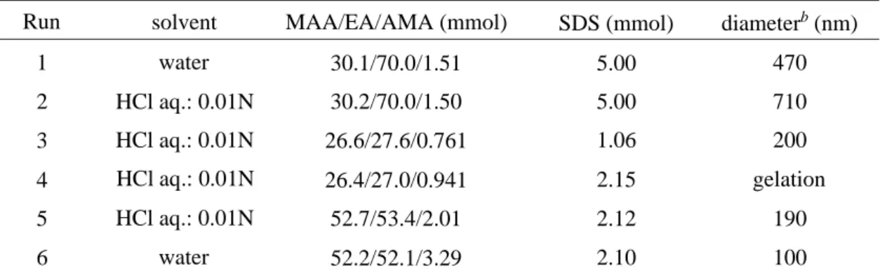
Table 3.1. Radical polymerizationa of 4 and 5.
a [monomer] = 1.15 M; Reaction time = 24 h. b The number-average molecular weight measured by GPC. c Relative ratio of the peak area (%).
389 (27)c, 210 (73)c 297 Run 1 2 3 4 5 6
3.4 Redox behavior of acyl nitroxide
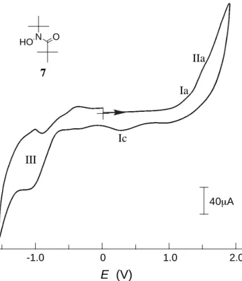
In order to gain information on the electronic structure of the acyl nitroxide, N-tert-butyl-N-pivaloylhydroxylamine 7 was prepared as a control sample of the precursor macromolecule 6, by referring to the preparation of 5. Figure 3.1 illustrates a cyclic voltammogram of 7 in dichloromethane at room temperature. The anodic sweep from 0 V (vs. Ag/AgCl) provided two obscure oxidation peaks at 1.22 and 1.48 V. The potential Ia at 1.22 V corresponds to the oxidation of hydroxylamine to the nitroxide radical through the one-electron removal and the following rapid deprotonation. The subsequent one IIa at 1.48 V is ascribed to the oxidation process from the nitroxide radical to the oxoammonium salt. However, there is no accompanying cathodic peak, which suggests that the electrochemical process is followed by a chemical reaction or a disproportionation reaction. A further cathodic sweep showed a peak Ic at 0.27 V due
40µA E (V) 0 1.0 2.0 -1.0 Ia IIa Ic III N HO O 7
Fig. 3.1. Cyclic voltammogram of 7 (1 mM) in CH2Cl2 with 0.1 M (C4H9)4NBF4 at room
to the rapid protonation of trace amounts of the nitroxide and the following one-electron reduction to yield the hydroxylamine. The electric currents observed for these redox processes were very weak, indicating difficulty in the oxidation or p-type redox reaction of this compound. On the other hand, a well-defined reversible redox wave III emerged at –1.05 V with the peak-to-peak separation of ca. 60 mV, which has never been seen in other nitroxide radicals like TEMPO.20
This wave was reversibly recorded in the repeated sweeps at room temperature. The stable n-type redox reaction of 7 is probably caused by the substitution of the electron-withdrawing carbonyl group. More extensive information on the redox products of acyl nitroxide will be obtained by changing the electrolyte, solvent, and pH in the electrochemical studies.
References
1.M. Kamachi, in K. Takemoto, R. M. Ottenbritte, M. Kamachi (eds.), “Functional Monomers and Polymers,” Marcel Dekker, New York, 1997, p. 149.
2.U. V. Korshak, T. V. Madvedeva, A. A. Ovchinnikov, and V. N. Spector, Nature, 326, 370 (1987).
3. E. J. Vlietstra, R. J. M. Nolte, J. W. Zwikker, W. Drenth, and E. W. Meijer, Macromolecules, 23, 946 (1990).
4. L. Dulog and S. Luts, Macromol. Chem., Rapid Commun., 14, 147 (1993).
5. P. Swobada, R. Saf, K. Hummel, F. Hofer, and R. Czaputa, Macromolecules, 28, 4255 (1995).
6. H. Nishide, T. Kaneko, S. Toriu, Y. Kuzumaki, and E. Tsuchida, Bull. Chem. Soc. Jpn.,
69, 499 (1996).
7. H. Oka, T. Tamura, Y. Miura, and Y. Teki, J. Mater. Chem., 11, 1364 (2001).
8. H. G. Aurich, in S. Patai, Z. Rappoport (eds.), “Nitrones, nitronates and nitroxides,” Wiley, Chichester, 1989, p. 313.
9. J. F. W. Keana, Chem. Rev., 78, 37 (1978). 10. M.-E. Brik, Heterocycles, 41, 2827 (1995).
11. J. Perkins and P. Ward, J. Chem. Soc., Chem. Commun., 1973, 883.
12. P. F. Alewood, S. A. Hussain, T. C. Jenkins, M. J. Perkins, A. H. Sharma, N. P. Y. Siew, and P. Ward, J. Chem. Soc., Perkin Trans. 1, 1978, 1066.
13. T. Miyazawa and T. Endo, J. Polym. Sci., Polym. Chem. Ed., 23, 2487 (1985).
14. F. MacCorquodale, J. A. Crayston, J. C. Walton, and D. J. Worsfold, Tetrahedron Lett.,
31, 771 (1990).
15. This compound has already been reported, but the yield was trace; H. G. Aurich and J. Trösken, Chem. Ber., 106, 3483 (1973).
16. E. Rozantzev, “Free Nitroxyl Radicals,” Plenum, London, 1970.
17. P. F. Alewood, I. C. Calder, and R. L. Richardson, Synthesis, 1981, 121.
18. M. K. Georges, R. P. N. Veregin, P. M. Kazmaier, and G. K. Hamer, Trends Polym. Sci., 2, 66 (1994).
19. C. J. Hawker, Acc. Chem. Res., 30, 373 (1997).
20. J. R. Fish, S. G. Swarts, M. D. Sevilla, and T. Malinski, J. Phys. Chem., 92, 3745 (1988).
Complexation of Gadolinium Ion with a
Poly(methacrylic acid) Nanoparticle and
its Magnetic Image
4.1 Introduction
4.2 Experimental section
4.3 Preparation of poly(methacrylic acid) nanoparticle 4.4 Complexation of gadolinium ion
4.5 Magnetic image of nanoparticle containing gadolinium ion References