This report presents the results of the PFMA for Oroville Dam, part of FERC Project No. In addition, four "Candidate PFMs" were described in the report along with fifteen "Risk Mitigation Measures" and eleven "Other Considerations".

General Project Description
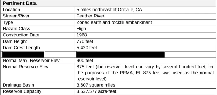
The portion of the complex covered in this PFMA consists of Oroville Dam, Hyatt Power Central, Oroville Flood Control Outlet (FCO), Oroville Emergency Spillway, Oroville. 875 feet (reservoir level can vary by several hundred feet, for PFMA purposes El. 875 feet was used as the normal reservoir level).

Dam
Flood Control Outlet
Emergency Spillway
Slope stability analyzes of slopes upstream and downstream of Oroville Dam (References and 147) are not current. During the PFMA workshop, the potential for rock erosion downstream of the emergency spillway toe was discussed. The leak develops at the right abutment contact between the dam and the left side of the Monolith no.
Water flows over the top of the dam at the place where there is the largest settlement. The uplift pressure at the base of the ogee section increases in response to the hydrodynamic loads. Seepage currents may occur into the foundation on the upstream side of the core.
Displacement/rupture along one of the existing shears in the dam foundation during seismic events. California Department of Water Resources, 1999, Structural Reevaluation of the Radial Gates at the Oroville Dam Spillway, February 1999. California Department of Water Resources, 2012, Comprehensive Review of Probable Maximum Flood (PMF) for Oroville Dam and Reservoir.
Intakes
Conveyance Systems
Hyatt Power Plant
Outlets
Vicinity Map and Project Drawings
Standard Operating Procedures
The potential cause of the "green spot" is discussed in the Oroville Dam Final Design Report – Volume I, August 1968 (Reference 17). The PFMA process has highlighted several areas of Oroville Dam that will require continued monitoring or further investigation to verify the performance of the dam.
Flood Loading Potential Failure Modes
- Conditions Relevant to Flood Loading Potential Failure Modes
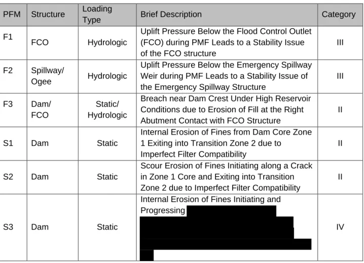
- PFM-F1 Uplift Pressure Below the Flood Control Outlet (FCO) During PMF
- PFM-F2 Uplift Pressure Below the Emergency Spillway Weir During PMF Leads
- PFM-F3 Breach Near Dam Crest Under High Reservoir Conditions due to
-F1: Uplift pressure under the flood control outlet (FCO) during PMF leads to a stability problem of the FCO structure. PFM-F2: The uplift pressure under the emergency spillway during PMF leads to a stability problem of the emergency spillway structure.

Static Loading Potential Failure Modes
Conditions Relevant to Static Loading PFMs
Third Inspection and Safety Review of Oroville-Thermalito Project Facilities, FERC Project No. Fourth Review of Inspection and Safety of Oroville-Thermalito Project Facilities, FERC Project No.

PFM-S1 Internal Erosion of Fines from Dam Core Zone 1 Exiting into Transition
PFM-S1: Internal erosion of fines from dam core zone 1 exiting transition zone 2 due to imperfect filter compliance. The development of the potential failure mode would be revealed by the well-designed toe seepage collection system and the increased seepage rate observed in the toe fin.
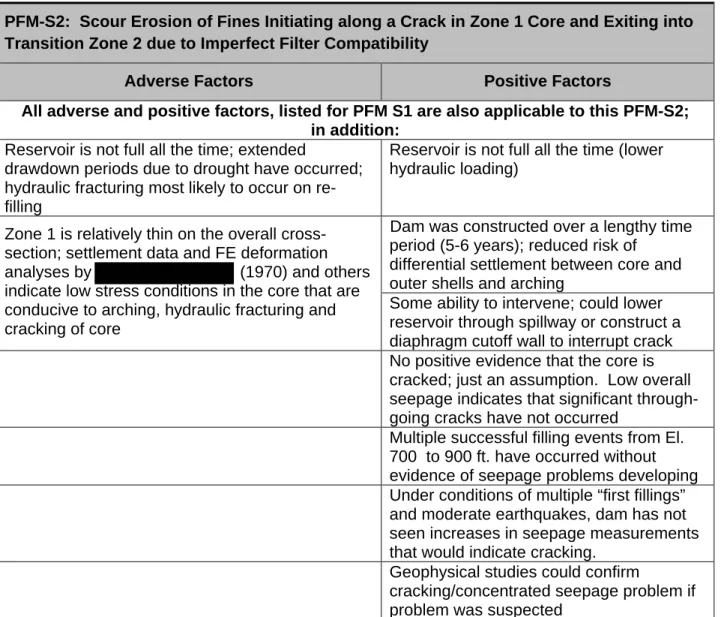
PFM-S2 Scour Erosion of Fines Initiating along a Crack in Zone 1 Core and
The majority of the workshop Core Team held the opinion that PFM-S2 is credible because the stress conditions in the core are conducive to crack formation and Zone 2 does not strictly meet the current criteria for filters. This PFM was not highlighted because there is no evidence that the core is cracked and leaking, based on the low overall seepage through the dam as measured at the downstream toe embankment.
PFM-S3 Internal Erosion of Fines Initiating and Progressing
The minority vote for Category IV believed that the potential for this failure mode was remote because of the wide width and favorable grading of the Zone 1 core, and because degradation of the core by cracking and loss of fines would not lead to failure of the dam. Similar potential failure modes or potential candidate failure modes previously identified in 2004 and 2009 Failure mode description. Two candidate PFMs were identified in the 2004 and 2009 PFMAs that were specific to hydraulic fracturing and cracking associated with elevated pressures at the tips of fractured instrumentation tubing.
This 2014 PFMA Workshop Core Team, as previously discussed, concluded that the Zone 2 filter is imperfect in accordance with modern filter design criteria, and thus cannot be used on its own to rule out potential failure modes. The previous Candidate 2 and 4, crack-related PFMs described above were considered to be adverse contributing factors in the overall development of PFM-S2.
Earthquake-Loading Potential Failure Modes
Conditions Relevant to Earthquake Loading PFMs
Piezometers in the core generally reflected the loading of the lake as it goes through annual fluctuations. The increases were attributed to increases in seepage f on the right side of the dam. The sidewalls of the crack may stand almost vertically and the crack remains open through the core.
Consequences: Head cutting carves a channel through the reef, causing a dam breach near the reef and an uncontrolled discharge of the reservoir basin. Seepage occurring from the upstream side of the core carries water into the new.

PFM-E3 Earthquake Occurs During a Wet Period in which “Green Spot” Area of
The loss of shear strength leads to subsidence and slope failure in the vicinity of the. Efforts are being made to place stabilizing rock fill in the toe of the slide area. PFM-E3 Seismic event increases the abutment seepage, possibly exacerbated by rainfall, saturating the embankment in the area of the "green spot".
Classification: Category III; Background: The safety factor against slope failure in the “green spot” area under saturated conditions is unknown. DWR would like to bring the issue of the "green spot" to a definitive solution.
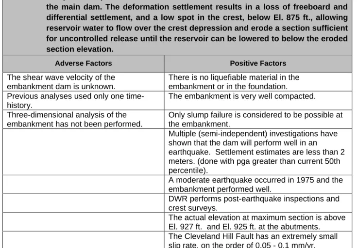
PFM-E4 Large Earthquake (on the Order of the 84th percentile) on the Cleveland
USBR, 1965, Hydraulic Model Studies of the Oroville Dam Powerplant Intake Structures – California Department of Water Resources, State of California, Report No. California Department of Water Resources, 1984, Memorandum Report – Oroville Dam, Evaluation of the Need for Replacement of Core Piezometers . Woodward-Clyde Consultants for the California Department of Water Resources, 1994, Fifth Safety Inspection Report of the Oroville Dam Facilities, May 1994.
California Department of Water Resources, 1997, Structural Inspection of the Radial Gates at Oroville Dam Spillway, Memorandum Report, May 1997. California Department of Water Resources, 2011, Structural Reevaluation of the Radial Gates at Oroville Dam Spillway, Memorandum Report.
PFM-E7 Seismic Forces Due to a Large Earthquake Damage the FCO Gates
PFM-E8 Earthquake Loading Under Normal Reservoir Pool Causes “Debonding”
Between the concrete at the base of the Ogee weir and the bedrock, Displacement of an Ogee section monolith resulting in partial release of the reservoir at approximately El. Seismic forces combined with hydrostatic and hydrodynamic forces in the concrete section of the dam in emergency spillway cause uplift pressures to develop at the base of the ogee dam. Uplift pressures lead to "swelling" at the base of the ridge section of the concrete pour.
Reduced sliding resistance at the base of the ogee section foundation interface results in sliding of the weir. The rock contact at the base of the ogee section is very rough on a macroscale, which provides favorable conditions for resisting sliding.
Operational Potential Failure Modes
The additional hydrodynamic loads cause the concrete foundation to 'loosen' from the foundation rock, causing it to shear and then slide along the 'loosened' interface. Rotation of the Ogee spillway section results in an opening at the contact between the FCO and Ogee sections that allows reservoir water to flow freely to Feather River until the reservoir level reaches an elevation of approximately 800 feet. Corrosion of metal structures, namely pipes and valves, was discussed in several Operational PFMs.
Chemicals carried in the water, as well as the pH of the water, can affect the potential for corrosion of pipes and valves at a dam. If risk mitigation measures were identified during the discussion, they are presented to the candidate PFM.
Flood Loading Candidate PFMs Not Carried Forward
Candidate F1: PMF Event Occurring in Feather River Basin and Canyon Dam
Rationale for not carrying PFM forward: The spillway is designed to accommodate flows that exceed the operational requirements of the flood control regulation plan (150,000 cfs). Candidate Description: Cavitation or spalling leads to loss of the concrete lining in the spill chute downstream of the FCO. Candidate F5: Loss of the spillway lining leads to erosion of the rock underlining the spillway.
Reason for not continuing with PFM: Damming the Feather River is considered highly unlikely due to the heavy flows that would occur if the emergency spillway were activated. An existing shift has been observed in the spoil material located to the left of the spillway.

Operational Candidate PFMs Not Carried Forward
Candidate Description: There are significant discharges from the FCO resulting in backwater conditions in the Feather River downstream of the Hyatt Power Plant. Due to the limited piezometric data currently available in the embankment, the importance of the dam readings. Finger dam readings are known to increase with precipitation, but additional information on how much increases with different precipitation totals and the rate and duration of changes in flow readings would be helpful.
Evaluate whether explosion damage resulting from the construction of the power plant contributed to the seepage problems at the left abutment. Examine the characterization of the shear zones intersecting the core as shown in the final geological report, and compare these to grout data in the area of the shear to see if they correlate.
Summary of Potential Failure Modes Identified
Uplift pressure under the flow control outlet (FCO) during PMF leads to a stability issue of the FCO structure. Uplift pressure under the Emergency Spillway embankment during PMF leads to a stability issue of the Emergency Spillway structure. Large earthquake (on the order of the 84th percentile) on the Cleveland Hills fault results in deformation and loss of freeboard and overthrusting of the crest of the dam.
Candidate F5 FCO Hydrologic Loss of spillway lining results in erosion of the rock underlining the spillway. Scouring of the soil and debris downstream of the emergency spillway is blocking the Feather River.
Summary of Potential Action Items Identified with Respect to Inspections,
Seepage Monitoring
Due to the limited number of currently operating piezometers in the dam (3) and questionable data for these instruments, the importance of seepage monitoring is high. Dam discharge is a critical measurement and the best indicator of seepage change within the dam and across the Zone 1 core. It is not known whether all of the seepage occurring at Oroville Dam is captured behind the seepage barrier and measured at the downstream dam.
Consider installing new piezometers in the downstream shell, downstream drainage blanket, and downstream rock foundations. The purpose of this new instrument is to improve the monitoring of the water table on the Oroville Dam's lower slope and the functionality of the horizontal drainage cover, and to determine whether the hydraulic gradients are up or down between the dam and the foundation below the downstream areas.
Other Dam Embankment Monitoring
USBR, 1965, Hydraulic Model Studies of the Flood Control Outlet and Spillway for Oroville Dam - California Department of Water Resources, State of California, Report No. California Department of Water Resources, 1968, Final Construction Report on Oroville Dam, Part IV, Oroville Dam Instrumentation . California Department of Water Resources, 1977, Drawings and Specifications for Repairs to the Oroville Dam Spillway, Specification No.
California Department of Water Resources, 2004; Oroville Dam Spillway; Landslide Evaluation Results, Project Geology Report No. California Department of Water Resources, 2012, Oroville Dam and Saddle Dams, Fault and Seismicity Reanalysis, Project Geology Report No. California Department of Water Resources, 2012, Long-Term Phreatic Surface Monitoring Plan of Oroville Dam.

Seismic Fragility Inventory
Inspections and Data Management