134
?
This skydiver is descending under a parachute at a steady rate. In this situation, which has a greater magnitude: the force of gravity or the upward force of the air on the skydiver?LEARNING GOALS
By studying this chapter, you will learn:
• How to use Newton’s first law to solve problems involving the forces that act on a body in equilibrium.
• How to use Newton’s second law to solve problems involving the forces that act on an accelerating body.
• The nature of the different types of friction forces—static friction, kinetic friction, rolling friction, and fluid resistance—and how to solve prob- lems that involve these forces.
• How to solve problems involving the forces that act on a body moving along a circular path.
• The key properties of the four funda- mental forces of nature.
5 APPLYING NEWTON’S LAWS
W e saw in Chapter 4 that Newton’s three laws of motion, the founda- tion of classical mechanics, can be stated very simply. But applying these laws to situations such as an iceboat skating across a frozen lake, a toboggan sliding down a hill, or an airplane making a steep turn requires analytical skills and problem-solving technique. In this chapter we’ll help you extend the problem-solving skills you began to develop in Chapter 4.
We’ll begin with equilibrium problems, in which we analyze the forces that act on a body at rest or moving with constant velocity. We’ll then consider bodies that are not in equilibrium, for which we’ll have to deal with the relationship between forces and motion. We’ll learn how to describe and analyze the contact force that acts on a body when it rests on or slides over a surface. We’ll also ana- lyze the forces that act on a body that moves in a circle with constant speed. We close the chapter with a brief look at the fundamental nature of force and the classes of forces found in our physical universe.
5.1 Using Newton’s First Law:
Particles in Equilibrium
We learned in Chapter 4 that a body is in equilibrium when it is at rest or mov-
ing with constant velocity in an inertial frame of reference. A hanging lamp, a
kitchen table, an airplane flying straight and level at a constant speed—all are
examples of equilibrium situations. In this section we consider only equilibrium
of a body that can be modeled as a particle. (In Chapter 11 we’ll see how to ana-
lyze a body in equilibrium that can’t be represented adequately as a particle,
such as a bridge that’s supported at various points along its span.) The essential
5.1 Using Newton’s First Law: Particles in Equilibrium 135
physical principle is Newton’s first law: When a particle is in equilibrium, the
net
force acting on it—that is, the vector sum of all the forces acting on it—must be zero:
(particle in equilibrium, vector form)
(5.1)We most often use this equation in component form:
(particle in equilibrium, component form)
(5.2)This section is about using Newton’s first law to solve problems dealing with bodies in equilibrium. Some of these problems may seem complicated, but the important thing to remember is that all problems involving particles in equilib- rium are done in the same way. Problem-Solving Strategy 5.1 details the steps you need to follow for any and all such problems. Study this strategy carefully, look at how it’s applied in the worked-out examples, and try to apply it yourself when you solve assigned problems.
aFx =
0
aFy =0
aFS ⴝ 0Problem-Solving Strategy 5.1
Newton’s First Law: Equilibrium of a Particle
IDENTIFY the relevant concepts: You must use Newton’s first law for any problem that involves forces acting on a body in equilibrium—that is, either at rest or moving with constant veloc- ity. For example, a car is in equilibrium when it’s parked, but also when it’s traveling down a straight road at a steady speed.
If the problem involves more than one body and the bodies inter- act with each other, you’ll also need to use Newton’s thirdlaw. This law allows you to relate the force that one body exerts on a second body to the force that the second body exerts on the first one.
Identify the target variable(s). Common target variables in equilibrium problems include the magnitude and direction (angle) of one of the forces, or the components of a force.
SET UPthe problemusing the following steps:
1. Draw a very simple sketch of the physical situation, showing dimensions and angles. You don’t have to be an artist!
2. Draw a free-body diagram for each body that is in equilibrium.
For the present, we consider the body as a particle, so you can represent it as a large dot. In your free-body diagram, do not include the other bodies that interact with it, such as a surface it may be resting on or a rope pulling on it.
3. Ask yourself what is interacting with the body by touching it or in any other way. On your free-body diagram, draw a force vec- tor for each interaction. Label each force with a symbol for the magnitudeof the force. If you know the angle at which a force is directed, draw the angle accurately and label it. Include the body’s weight, unless the body has negligible mass. If the mass is given, use to find the weight. A surface in contact with the body exerts a normal force perpendicular to the surface and possibly a friction force parallel to the surface. A rope or chain exerts a pull (never a push) in a direction along its length.
4. Do notshow in the free-body diagram any forces exerted bythe body on any other body. The sums in Eqs. (5.1) and (5.2)
w = mg
include only forces that act onthe body. For each force on the body, ask yourself “What other body causes that force?” If you can’t answer that question, you may be imagining a force that isn’t there.
5. Choose a set of coordinate axes and include them in your free-body diagram. (If there is more than one body in the problem, choose axes for each body separately.) Label the positive direction for each axis. If a body rests or slides on a plane surface, it usually simplifies things to choose axes that are parallel and perpendicular to this surface, even when the plane is tilted.
EXECUTEthe solutionas follows:
1. Find the components of each force along each of the body’s coordinate axes. Draw a wiggly line through each force vector that has been replaced by its components, so you don’t count it twice. The magnitude of a force is always positive, but its componentsmay be positive or negative.
2. Set the sum of all x-components of force equal to zero. In a sep- arate equation, set the sum of all y-components equal to zero.
(Neveradd x- and y-components in a single equation.) 3. If there are two or more bodies, repeat all of the above steps for
each body. If the bodies interact with each other, use Newton’s third law to relate the forces they exert on each other.
4. Make sure that you have as many independent equations as the number of unknown quantities. Then solve these equations to obtain the target variables.
EVALUATEyour answer:Look at your results and ask whether they make sense. When the result is a symbolic expression or formula, check to see that your formula works for any special cases (partic- ular values or extreme cases for the various quantities) for which you can guess what the results ought to be.
Example 5.1
One-dimensional equilibrium: Tension in a massless rope
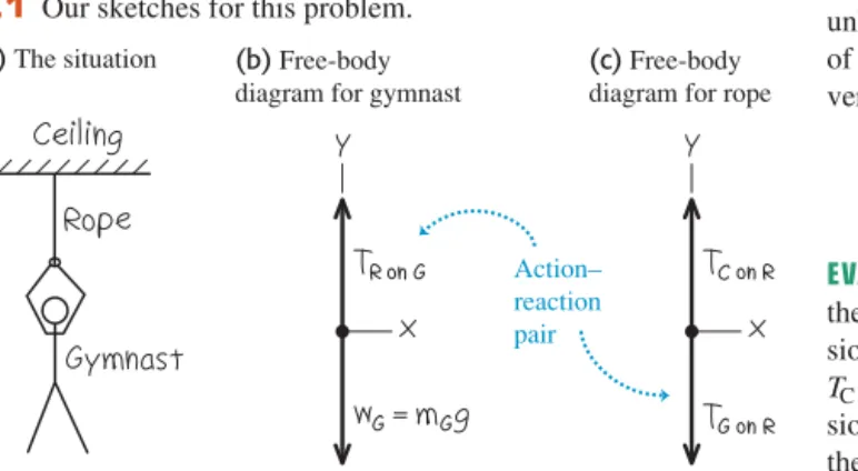
A gymnast with mass suspends herself from the lower end of a hanging rope of negligible mass. The upper end of the rope is attached to the gymnasium ceiling. (a) What is the gym- nast’s weight? (b) What force (magnitude and direction) does the rope exert on her? (c) What is the tension at the top of the rope?
S O L U T I O N
IDENTIFY and SET UP:The gymnast and the rope are in equilib- rium, so we can apply Newton’s first law to both bodies. We’ll use Newton’s third law to relate the forces that they exert on each other. The target variables are the gymnast’s weight, the force that the bottom of the rope exerts on the gymnast
and the force that the ceiling exerts on the top of the rope Figure 5.1 shows our sketch of the situation and free-body diagrams for the gymnast and for the rope. We take the positivey-axis to be upward in each diagram. Each force acts in the vertical direction and so has only a y-component.
The forces (the upward force of the rope on the gym- nast, Fig. 5.1b) and (the downward force of the gymnast on the rope, Fig. 5.1c) form an action–reaction pair. By Newton’s third law, they must have the same magnitude.
TG on R TR on G 1call it TC on R2.
1call it TR on G2; wG;
mG = 50.0 kg Note that Fig. 5.1c includes only the forces that act onthe rope.
In particular, it doesn’t include the force that the ropeexerts on the ceiling(compare the discussion of the apple in Conceptual Exam- ple 4.9 in Section 4.5). Similarly, the force that the rope exerts on the ceiling doesn’t appear in Fig. 5.1c.
EXECUTE:(a) The magnitude of the gymnast’s weight is the prod- uct of her mass and the acceleration due to gravity, g:
(b) The gravitational force on the gymnast (her weight) points in the negative y-direction, so its y-component is The upward force of the rope on the gymnast has unknown magnitude and positive y-component We find this using Newton’s first law:
The rope pulls upon the gymnast with a force of magnitude 490 N. (By Newton’s third law, the gymnast pulls downon the rope with a force of the same magnitude,
(c) We have assumed that the rope is weightless, so the only forces on it are those exerted by the ceiling (upward force of unknown magnitude ) and by the gymnast (downward force of magnitude From Newton’s first law, the net vertical force on the rope in equilibrium must be zero:
EVALUATE:Thetensionat any point in the rope is the magnitude of the force that acts at that point. For this weightless rope, the ten- sion at the lower end has the same value as the tension at the upper end. For such an ideal weightless rope, the ten- sion has the same value at any point along the rope’s length. (See the discussion in Conceptual Example 4.10 in Section 4.5.) TC on R
TG on R
TC on R= TG on R = 490 N
Rope: aFy = TC on R + 1-TG on R2 = 0 so TG on R = 490 N).
TC on R
TG on R = 490 N.) TR on G TR on G = wG = 490 N
Gymnast: aFy = TR on G + 1-wG2 = 0 so +TR on G.
TR on G
-wG. wG = mGg = 150.0 kg219.80 m>s22 = 490 N
Action–
reaction pair (a) The situation (b) Free-body
diagram for gymnast
(c) Free-body diagram for rope 5.1 Our sketches for this problem.
Example 5.2
One-dimensional equilibrium: Tension in a rope with mass
Find the tension at each end of the rope in Example 5.1 if the weight of the rope is 120 N.
S O L U T I O N
IDENTIFY and SET UP:As in Example 5.1, the target variables are the magnitudes and of the forces that act at the bot- tom and top of the rope, respectively. Once again, we’ll apply Newton’s first law to the gymnast and to the rope, and use New- ton’s third law to relate the forces that the gymnast and rope exert on each other. Again we draw separate free-body diagrams for the gymnast (Fig. 5.2a) and the rope (Fig. 5.2b). There is now a third force acting on the rope, however: the weight of the rope, of mag- nitude
EXECUTE: The gymnast’s free-body diagram is the same as in Example 5.1, so her equilibrium condition is also the same. From
wR = 120 N.
TC on R TG on R
Newton’s third law, and we again have
The equilibrium condition for the rope is now
Note that the y-component of is positive because it points in the but the y-components of both and are negative. We solve for and substitute the values
and
EVALUATE:When we include the weight of the rope, the tension isdifferentat the rope’s two ends: 610 N at the top and 490 N at
TC on R = TG on R + wR = 490 N + 120 N = 610 N wR = 120 N:
TG on R = TR on G = 490 N TC on R
wR TG on R +y-direction,
TC on R
Rope: aFy = TC on R + 1-TG on R2 + 1-wR2 = 0 gFy = 0
TR on G = TG on R = wG = 490 N Gymnast: aFy = TR on G + 1-wG2 = 0 so
TR on G = TG on R,
the bottom. The force exerted by the ceiling has to hold up both the 490-N weight of the gymnast and the 120-N weight of the rope.
To see this more clearly, we draw a free-body diagram for a composite body consisting of the gymnast and rope together (Fig. 5.2c). Only two external forces act on this composite body:
the force exerted by the ceiling and the total weight (The forces and are internal to the composite body. Newton’s first law applies only to external forces, so these internal forces play no role.) Hence Newton’s first law applied to this composite body is
and so
Treating the gymnast and rope as a composite body is simpler, but we can’t find the tension at the bottom of the rope by this method. Moral: Whenever you have more than one body in a problem involving Newton’s laws, the safest approach is to treat each body separately.
TG on R TC on R = wG + wR = 610 N.
Composite body: aFy = TC on R + 3-1wG + wR24 = 0 TR on G
TG on R wG + wR= 490 N + 120 N = 610 N.
TC on R
TC on R = 610 N
5.1 Using Newton’s First Law: Particles in Equilibrium 137
Action–
reaction pair (a) Free-body diagram for gymnast
(b) Free-body diagram for rope
(c) Free-body diagram for gymnast and rope as a composite body 5.2 Our sketches for this problem, including the weight of the rope.
Example 5.3
Two-dimensional equilibrium
In Fig. 5.3a, a car engine with weight whangs from a chain that is linked at ring Oto two other chains, one fastened to the ceiling and the other to the wall. Find expressions for the tension in each of the three chains in terms of w. The weights of the ring and chains are negligible compared with the weight of the engine.
S O L U T I O N
IDENTIFY and SET UP:The target variables are the tension magni- tudes and in the three chains (Fig. 5.3a). All the bodies are in equilibrium, so we’ll use Newton’s first law. We need three independent equations, one for each target variable. However, applying Newton’s first law to just one body gives us only two equations, as in Eqs. (5.2). So we’ll have to consider more than one body in equilibrium. We’ll look at the engine (which is acted on by ) and the ring (which is acted on by all three chains and so is acted on by all three tensions).
Figures 5.3b and 5.3c show our free-body diagrams and choice of coordinate axes. There are two forces that act on the engine: its weightwand the upward force T1exerted by the vertical chain.
T1
T3 T2, T1,
Three forces act on the ring: the tensions from the vertical chain the horizontal chain and the slanted chain Because the vertical chain has negligible weight, it exerts forces of the same magnitude at both of its ends (see Example 5.1). (If the weight of this chain were not negligible, these two forces would have different magnitudes like the rope in Example 5.2.) The weight of the ring is also negligible, which is why it isn’t included in Fig. 5.3c.
EXECUTE: The forces acting on the engine are along the y-axis only, so Newton’s first law says
The horizontal and slanted chains don’t exert forces on the engine itself because they are not attached to it. These forces do appear when we apply Newton’s first law to the ring, however. In the free-body diagram for the ring (Fig. 5.3c), remember that
and are the magnitudesof the forces. We resolve the force with magnitude into its x- and y-components. The ring is in equilibrium, so using Newton’s first law we can write (separate)
T3 T3 T2,
T1, Engine: aFy = T1 + 1-w2 = 0 and T1 = w
T1
1T32. 1T22,
1T12,
(a)Engine, chains, and ring
T1 T3 T2
O 60°
(b)Free-body diagram for engine
(c)Free-body diagram for ring O 5.3 (a)The situation. (b),(c)Our free-body diagrams.
Continued
equations stating that the x- and y-components of the net force on the ring are zero:
Because (from the engine equation), we can rewrite the second ring equation as
We can now use this result in the first ring equation:
T2 = T3 cos 60°= wcos 60°
sin 60° = 0.58w T3 = T1
sin 60° = w
sin 60° = 1.2w T1 = w
Ring: aFy = T3 sin 60° + 1-T12 = 0 Ring: aFx = T3 cos 60°+ 1-T22 = 0
EVALUATE:The chain attached to the ceiling exerts a force on the ring with a verticalcomponent equal to which in turn is equal tow. But this force also has a horizontal component, so its magni- tude is somewhat larger than w. This chain is under the greatest tension and is the one most susceptible to breaking.
To get enough equations to solve this problem, we had to con- sider not only the forces on the engine but also the forces acting on a second body (the ring connecting the chains). Situations like this are fairly common in equilibrium problems, so keep this technique in mind.
T3
T1,
Example 5.4
An inclined plane
A car of weight wrests on a slanted ramp attached to a trailer (Fig. 5.4a). Only a cable running from the trailer to the car pre- vents the car from rolling off the ramp. (The car’s brakes are off and its transmission is in neutral.) Find the tension in the cable and the force that the ramp exerts on the car’s tires.
S O L U T I O N
IDENTIFY:The car is in equilibrium, so we use Newton’s first law.
The ramp exerts a separate force on each of the car’s tires, but for simplicity we lump these forces into a single force. For a further simplification, we’ll neglect any friction force the ramp exerts on the tires (see Fig. 4.2b). Hence the ramp only exerts a force on the car that is perpendicular to the ramp. As in Section 4.1, we call this force the normalforce (see Fig. 4.2a). The two target variables are the magnitude nof the normal force and the magnitude Tof the tension in the cable.
SET UP:Figure 5.4 shows the situation and a free-body diagram for the car. The three forces acting on the car are its weight (mag- nitudew), the tension in the cable (magnitude T), and the normal force (magnitude n). Note that the angle between the ramp and the horizontal is equal to the angle between the weight vector and the downward normal to the plane of the ramp. Note also that we choose the x- and y-axes to be parallel and perpendicular to the ramp so that we only need to resolve one force (the weight) intox- and y-components. If we chose axes that were horizontal and vertical, we’d have to resolve both the normal force and the tension into components.
wS
a a
EXECUTE:To write down the x- and y-components of Newton’s first law, we must first find the components of the weight. One complica- tion is that the angle in Fig. 5.4b is notmeasured from the toward the Hence we cannotuse Eqs. (1.6) directly to find the components. (You may want to review Section 1.8 to make sure that you understand this important point.)
One way to find the components of is to consider the right triangles in Fig. 5.4b. The sine of is the magnitude of the x-component of (that is, the side of the triangle opposite ) divided by the magnitude w (the hypotenuse of the triangle).
Similarly, the cosine of is the magnitude of the y-component (the side of the triangle adjacent to ) divided by w. Both com- ponents are negative, so and
Another approach is to recognize that one component of must involve while the other component involves To decide which is which, draw the free-body diagram so that the angle is noticeably smaller or larger than 45°. (You’ll have to fight the natural tendency to draw such angles as being close to 45°.) We’ve drawn Fig. 5.4b so that is smaller than 45°, so is less than The figure shows that the x-component of is smaller than the y-component, so the x-component must involve and they-component must involve We again find
and
In Fig. 5.4b we draw a wiggly line through the original vector representing the weight to remind us not to count it twice. New- ton’s first law gives us
(Remember that T,w, and nare all magnitudesof vectors and are therefore all positive.) Solving these equations for Tandn, we find
EVALUATE:Our answers for Tandndepend on the value of . To check this dependence, let’s look at some special cases. If the ramp
is horizontal we get and As you might
expect, no cable tension Tis needed to hold the car, and the normal forcenis equal in magnitude to the weight. If the ramp is vertical we get T = wand n = 0. The cable tension Tsupports
1a = 90°2,
n= w.
T= 0 a = 02,
1
a n = w cos a
T = w sin a
aFy = n+ 1-w cos a2 = 0 aFx = T+ 1-w sin a2 = 0 wy = -w cos a.
wx = -w sin a cosa.
sina wS
cosa.
sina a
a
cosa. sina
wS wy = -w cos a. wx = -w sin aa
a
a
wS a
wS
+y-axis.
+x-axis a
w sin a
w cos a w
T x
a a
y n
w T n
(b) Free-body diagram for car (a) Car on ramp
We replace the weight by its components.
5.4 A cable holds a car at rest on a ramp.
all of the car’s weight, and there’s nothing pushing the car against the ramp.
CAUTION Normal force and weight may not be equal It’s a com- mon error to automatically assume that the magnitude nof the nor- mal force is equal to the weight w: Our result shows that this is not true in general. It’s always best to treat nas a variable and solve for its value, as we have done here. ❙
5.1 Using Newton’s First Law: Particles in Equilibrium 139 How would the answers for Tandnbe affected if the car were being pulled up the ramp at a constant speed? This, too, is an equilibrium situation, since the car’s velocity is con- stant. So the calculation is the same, and Tandnhave the same values as when the car is at rest. (It’s true that Tmust be greater than to startthe car moving up the ramp, but that’s not what we asked.)
w sin a
Example 5.5
Equilibrium of bodies connected by cable and pulley
Blocks of granite are to be hauled up a 15° slope out of a quarry, and dirt is to be dumped into the quarry to fill up old holes. To sim- plify the process, you design a system in which a granite block on a cart with steel wheels (weight including both block and cart) is pulled uphill on steel rails by a dirt-filled bucket (weight including both dirt and bucket) that descends vertically into the quarry (Fig. 5.5a). How must the weights and be related in order for the system to move with constant speed? Ignore friction in the pulley and wheels, and ignore the weight of the cable.
S O L U T I O N
IDENTIFY and SET UP:The cart and bucket each move with a con- stant velocity (in a straight line at constant speed). Hence each body is in equilibrium, and we can apply Newton’s first law to each. Our target is an expression relating the weights and .
Figure 5.5b shows our idealized model for the system, and Figs. 5.5c and 5.5d show our free-body diagrams. The two forces on the bucket are its weight and an upward tension exerted by the cable. As for the car on the ramp in Example 5.4, three forces act on the cart: its weight a normal force of magnitude n exerted by the rails, and a tension force from the cable. (We’re ignoring friction, so we assume that the rails exert no force on the cart parallel to the incline.) Note that we orient the axes differ-
w1, w2
w2 w1 w2 w1
w2, w1,
ently for each body; the choices shown are the most convenient ones.
We’re assuming that the cable has negligible weight, so the ten- sion forces that the cable exerts on the cart and on the bucket have the same magnitude T. As we did for the car in Example 5.4, we represent the weight of the cart in terms of its x- and y-components.
EXECUTE:Applying to the bucket in Fig. 5.5c, we find
Applying to the cart (and block) in Fig. 5.5d, we get
Equating the two expressions for T, we find
EVALUATE: Our analysis doesn’t depend at all on the direction in which the cart and bucket move. Hence the system can move with constant speed in eitherdirection if the weight of the dirt and bucket is 26% of the weight of the granite block and cart. What would happen if w2were greater than 0.26w1?If it were less than 0.26w1?
w2 = w1 sin 15° = 0.26w1
aFx = T+ 1-w1 sin 15°2 = 0 so T = w1 sin 15°
gFx = 0
aFy = T + 1-w22 = 0 so T = w2 gFy = 0
15°
Cart
Bucket
(a) Dirt-filled bucket pulls cart with granite block
(b) Idealized model of the system
(c) Free-body diagram for bucket
(d) Free-body diagram for cart 5.5 (a)The situation. (b)Our idealized model. (c),(d)Our free-body diagrams.
Test Your Understanding of Section 5.1 A traffic light of weight w hangs from two lightweight cables, one on each side of the light. Each cable hangs at a 45° angle from the horizontal. What is the tension in each cable? (i)
(ii) (iii) w>12; w; (iv) w12 ;(v) 2w. ❙
w>2;
?
Notice that we didn’t need the equation for the cart and block. Can you use this to show that n= w1cos 15°?
gFy = 0
5.2 Using Newton’s Second Law:
Dynamics of Particles
We are now ready to discuss dynamics problems. In these problems, we apply Newton’s second law to bodies on which the net force is not zero. These bodies are
notin equilibrium and hence are accelerating. The net force on the body is equal to the mass of the body times its acceleration:
(Newton’s second law, vector form)
(5.3)We most often use this relationship in component form:
(5.4)
The following problem-solving strategy is very similar to Problem-Solving Strategy 5.1 for equilibrium problems in Section 5.1. Study it carefully, watch how we apply it in our examples, and use it when you tackle the end-of-chapter problems. You can solve any dynamics problem using this strategy.
CAUTION doesn’t belong in free-body diagrams Remember that the quantity is the resultof forces acting on a body, nota force itself; it’s not a push or a pull exerted by anything in the body’s environment. When you draw the free-body diagram for an acceler- ating body (like the fruit in Fig. 5.6a), make sure you never include the force”
because there is no such force(Fig. 5.6c). You should review Section 4.3 if you’re not clear on this point. Sometimes we draw the acceleration vector alongsidea free-body diagram, as in Fig. 5.6b. But we neverdraw the acceleration vector with its tail touching the body (a position reserved exclusively for the forces that act on the body). ❙
Sa
“maS maS maS
(Newton’s second law, component form)
aFx=maxaFy=may
aFS ⴝ maS
You can safely draw the acceleration vector to one side of the diagram.
This vector doesn’t belong in a free-body diagram because ma is not a force.
w ma y
x
(b) Correct free-body diagram
w ay
y x
Only the force of gravity acts on this falling fruit.
(a)
S
(c) Incorrect free-body diagram RIGHT!
WRONG
5.6 Correct and incorrect free-body dia- grams for a falling body.
Problem-Solving Strategy 5.2
Newton’s Second Law: Dynamics of Particles
IDENTIFYthe relevant concepts:You have to use Newton’s second law for anyproblem that involves forces acting on an accelerating body.
Identify the target variable—usually an acceleration or a force.
If the target variable is something else, you’ll need to select another concept to use. For example, suppose the target variable is how fast a sled is moving when it reaches the bottom of a hill. Newton’s second law will let you find the sled’s acceleration; you’ll then use the constant-acceleration relationships from Section 2.4 to find velocity from acceleration.
SET UPthe problemusing the following steps:
1. Draw a simple sketch of the situation that shows each moving body. For each body, draw a free-body diagram that shows all the forces acting onthe body. (The acceleration of a body is determined by the forces that act on it, notby the forces that it exerts on anything else.) Make sure you can answer the ques- tion “What other body is applying this force?” for each force in your diagram. Never include the quantity in your free-body diagram; it’s not a force!
2. Label each force with an algebraic symbol for the force’s magnitude.Usually, one of the forces will be the body’s weight;
it’s usually best to label this as
3. Choose your x- and y-coordinate axes for each body, and show them in its free-body diagram. Be sure to indicate the positive direction for each axis. If you know the direction of the acceler- ation, it usually simplifies things to take one positive axis along that direction. If your problem involves two or more bodies that
w = mg.
maS
accelerate in different directions, you can use a different set of axes for each body.
4. In addition to Newton’s second law, identify any other equations you might need. For example, you might need one or more of the equations for motion with constant accelera- tion. If more than one body is involved, there may be relation- ships among their motions; for example, they may be connected by a rope. Express any such relationships as equations relating the accelerations of the various bodies.
EXECUTEthe solutionas follows:
1. For each body, determine the components of the forces along each of the body’s coordinate axes. When you represent a force in terms of its components, draw a wiggly line through the orig- inal force vector to remind you not to include it twice.
2. Make a list of all the known and unknown quantities. In your list, identify the target variable or variables.
3. For each body, write a separate equation for each component of Newton’s second law, as in Eqs. (5.4). In addition, write any additional equations that you identified in step 4 of “Set Up.”
(You need as many equations as there are target variables.) 4. Do the easy part—the math! Solve the equations to find the tar-
get variable(s).
EVALUATEyour answer:Does your answer have the correct units?
(When appropriate, use the conversion ) Does it have the correct algebraic sign? When possible, consider particular values or extreme cases of quantities and compare the results with your intuitive expectations. Ask, “Does this result make sense?”
1 N = 1 kg
#
m>s2. gFSⴝmaS,5.2 Using Newton’s Second Law: Dynamics of Particles 141
Example 5.6
Straight-line motion with a constant force
An iceboat is at rest on a frictionless horizontal surface (Fig. 5.7a).
A wind is blowing along the direction of the runners so that 4.0 s after the iceboat is released, it is moving at (about or ). What constant horizontal force does the wind exert on the iceboat? The combined mass of iceboat and rider is 200 kg.
S O L U T I O N
IDENTIFY and SET UP:Our target variable is one of the forces acting on the accelerating iceboat, so we need to use Newton’s second law. The forces acting on the iceboat and rider (considered as a unit) are the weight w, the normal force nexerted by the sur- face, and the horizontal force . Figure 5.7b shows the free-body diagram. The net force and hence the acceleration are to the right, so we chose the positive x-axis in this direction. The acceleration isn’t given; we’ll need to find it. Since the wind is assumed to exert a constant force, the resulting acceleration is constant and we can use one of the constant-acceleration formulas from Section 2.4.
FW
1FW2 FW 13 mi>h
22 km>h,
6.0 m>s
The iceboat starts at rest its initial x-velocity is and it attains an x-velocity after an elapsed time
To relate the x-acceleration to these quantities we use Eq. (2.8), There is no vertical acceleration, so we expect that the normal force on the iceboat is equal in magnitude to the iceboat’s weight.
EXECUTE: The known quantities are the mass the
initial and final x-velocities and and the
elapsed time The three unknownquantities are the accel- eration the normal force n, and the horizontal force . Hence we need three equations.
The first two equations are the x- and y-equations for Newton’s second law. The force is in the positive x-direction, while the forcesnand are in the positive and negative y-directions, respectively. Hence we have
so
The third equation is the constant-acceleration relationship, Eq. (2.8):
To find we first solve this third equation for and then substitute the result into the equation:
Since 1 the final answer is
EVALUATE:Our answers for and nhave the correct units for a force, and (as expected) the magnitude nof the normal force is equal to mg. Does it seem reasonable that the force is substan- tiallylessthanmg?
FW FW
FW= 300 N 1about 67 lb2 kg
#
m>s2 = 1 N,FW = max = 1200 kg211.5 m>s22 = 300 kg
#
m>s2 ax = vx - v0xt = 6.0 m>s - 0 m>s
4.0 s = 1.5 m>s2 gFx
ax FW,
vx = v0x + axt
n = mg aFy = n + 1-mg2 = 0
aFx = FW = max w = mg
FW
FW ax,
t = 4.0 s.
vx = 6.0 m>s, v0x = 0
m= 200 kg, vx = v0x + axt.
ax
t = 4.0 s.
vx = 6.0 m>s
v0x = 02 1
B1
(a) Iceboat and rider on frictionless ice (b) Free-body diagram for iceboat and rider 5.7 (a)The situation. (b)Our free-body diagram.
Example 5.7
Straight-line motion with friction
Suppose a constant horizontal friction force with magnitude 100 N opposes the motion of the iceboat in Example 5.6. In this case, what constant force must the wind exert on the iceboat to cause the same constant x-acceleration
S O L U T I O N
IDENTIFY and SET UP: Again the target variable is We are given the x-acceleration, so to find all we need is Newton’s second law. Figure 5.8 shows our new free-body diagram. The only difference from Fig. 5.7b is the addition of the friction force which points opposite the motion. (Note that the magnitude is a positive quantity, but the component in the x-direction is negative, equal to or ) Because the wind must now overcome the friction force to yield the same accelera- tion as in Example 5.6, we expect our answer for to be greater than the 300 N we found there.
FW -100 N.
-ƒ ƒx
ƒ = 100 N
Sƒ ,
FW
FW. ax = 1.5 m>s2?
FW
5.8 Our free-body diagram for the iceboat and rider with a fric- tion force opposing the motion.ƒS
Continued
EXECUTE: Two forces now have x-components: the force of the wind and the friction force. The x-component of Newton’s second law gives
FW = max + ƒ = 1200 kg211.5 m>s22 + 1100 N2 = 400 N aFx = FW + 1-ƒ2 = max
EVALUATE: The required value of is 100 N greater than in Example 5.6 because the wind must now push against an addi- tional 100-N friction force.
FW
Example 5.8
Tension in an elevator cable
An elevator and its load have a combined mass of 800 kg (Fig. 5.9a).
The elevator is initially moving downward at it slows to a stop with constant acceleration in a distance of 25.0 m. What is the tension Tin the supporting cable while the elevator is being brought to rest?
S O L U T I O N
IDENTIFY and SET UP:The target variable is the tension T, which we’ll find using Newton’s second law. As in Example 5.6, we’ll determine the acceleration using a constant-acceleration formula.
Our free-body diagram (Fig. 5.9b) shows two forces acting on the elevator: its weight wand the tension force Tof the cable. The ele- vator is moving downward with decreasing speed, so its accelera- tion is upward; we chose the positive y-axis to be upward.
The elevator is moving in the negative y-direction, so its initial y-velocity and its y-displacement are both negative:
and The final y-velocity is
To find the y-acceleration from this information, we’ll
use Eq. (2.13) in the form Once we
have we’ll substitute it into the y-component of Newton’s sec- ond law from Eqs. (5.4) and solve for T. The net force must be upward to give an upward acceleration, so we expect Tto be greater than the weight
EXECUTE:First let’s write out Newton’s second law. The tension force acts upward and the weight acts downward, so
We solve for the target variable T:
T = w + may = mg + may = m1g + ay2 aFy = T + 1-w2 = may
7840 N.
w = mg = 1800 kg219.80 m>s22 = ay,
vy2 = v 20y + 2ay1y - y02. ay
vy = 0.
y - y0 = -25.0 m.
v0y = -10.0 m>s
y - y0 v0y
10.0 m>s;
To determine we rewrite the constant-acceleration equation
The acceleration is upward (positive), just as it should be.
Now we can substitute the acceleration into the equation for the tension:
EVALUATE:The tension is greater than the weight, as expected. Can you see that we would get the same answers for and Tif the elevator were moving upward and gaining speed at a rate of 2.00 m>s2?
ay
= 9440 N
T = m1g + ay2 = 1800 kg219.80 m>s2 + 2.00 m>s22 ay = vy2 - v 20y
21y - y02 = 1022 - 1-10.0 m>s22
21-25.0 m2 = +2.00 m>s2 vy2 = v 20y + 2ay1y - y02:
ay,
(b) Free-body diagram for elevator
(a) Descending elevator
Moving down with decreasing speed
5.9 (a)The situation. (b)Our free-body diagram.
Example 5.9
Apparent weight in an accelerating elevator
A 50.0-kg woman stands on a bathroom scale while riding in the elevator in Example 5.8. What is the reading on the scale?
S O L U T I O N
IDENTIFY and SET UP:The scale (Fig. 5.10a) reads the magnitude of the downward force exerted by the woman on the scale. By Newton’s third law, this equals the magnitude of the upward nor- mal force exerted bythe scale onthe woman. Hence our target variable is the magnitude nof the normal force. We’ll find nby applying Newton’s second law to the woman. We already know her acceleration; it’s the same as the acceleration of the elevator, which we calculated in Example 5.8.
Figure 5.10b shows our free-body diagram for the woman.
The forces acting on her are the normal force n exerted by the scale and her weightw = mg = 150.0 kg219.80 m>s22 = 490 N.
(b) Free-body diagram for woman
(a) Woman in a descending elevator
Moving down with decreasing speed
5.10 (a)The situation. (b)Our free-body diagram.
(The tension force, which played a major role in Example 5.8, doesn’t appear here because it doesn’t act on the woman.) From Example 5.8, they-acceleration of the elevator and of the woman is As in Example 5.8, the upward force on the body accelerating upward (in this case, the normal force on the woman) will have to be greater than the body’s weight to produce the upward acceleration.
EXECUTE:Newton’s second law gives
EVALUATE:Our answer for nmeans that while the elevator is stop- ping, the scale pushes up on the woman with a force of 590 N. By Newton’s third law, she pushes down on the scale with the same force. So the scale reads 590 N, which is 100 N more than her actual
= 150.0 kg219.80 m>s2 + 2.00 m>s22 = 590 N n = mg + may = m1g + ay2
aFy = n + 1-mg2 = may ay = +2.00 m>s2.
5.2 Using Newton’s Second Law: Dynamics of Particles 143 weight. The scale reading is called the passenger’s apparent weight.
The woman feelsthe floor pushing up harder on her feet than when the elevator is stationary or moving with constant velocity.
What would the woman feel if the elevator were accelerating downward,so that This would be the case if the elevator were moving upward with decreasing speed or moving downward with increasing speed. To find the answer for this situa- tion, we just insert the new value of in our equation for n:
Now the woman feels as though she weighs only 390 N, or 100 N lessthan her actual weight w.
You can feel these effects yourself; try taking a few steps in an elevator that is coming to a stop after descending (when your apparent weight is greater than w) or coming to a stop after ascend- ing (when your apparent weight is less than w).
= 390 N
n = m1g+ ay2 = 150.0 kg239.80 m>s2 + 1-2.00 m>s224 ay
ay = -2.00 m>s2?
Apparent Weight and Apparent Weightlessness
Let’s generalize the result of Example 5.9. When a passenger with mass m rides in an elevator with y-acceleration a scale shows the passenger’s apparent weight to be
When the elevator is accelerating upward, is positive and n is greater than the passenger’s weight When the elevator is accelerating downward, is negative and n is less than the weight. If the passenger doesn’t know the elevator is accelerating, she may feel as though her weight is changing; indeed, this is just what the scale shows.
The extreme case occurs when the elevator has a downward acceleration
—that is, when it is in free fall. In that case and the passenger
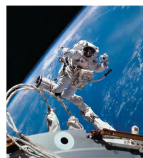
seemsto be weightless. Similarly, an astronaut orbiting the earth with a space- craft experiences apparent weightlessness (Fig. 5.11). In each case, the person is not truly weightless because a gravitational force still acts. But the person’s sensations in this free-fall condition are exactly the same as though the person were in outer space with no gravitational force at all. In both cases the person and the vehicle (elevator or spacecraft) fall together with the same accelera- tion
g, so nothing pushes the person against the floor or walls of the vehicle.n =
0
ay = -gay w = mg.
ay n = m1g + ay2
ay
,
5.11 Astronauts in orbit feel “weightless”
because they have the same acceleration as their spacecraft—notbecause they are “out- side the pull of the earth’s gravity.” (If no gravity acted on them, the astronauts and their spacecraft wouldn’t remain in orbit, but would fly off into deep space.)
Example 5.10
Acceleration down a hill
A toboggan loaded with students (total weight w) slides down a snow-covered slope. The hill slopes at a constant angle , and the toboggan is so well waxed that there is virtually no friction. What is its acceleration?
S O L U T I O N
IDENTIFY and SET UP: Our target variable is the acceleration, which we’ll find using Newton’s second law. There is no friction, so only two forces act on the toboggan: its weight wand the nor- mal force nexerted by the hill.
Figure 5.12 shows our sketch and free-body diagram. As in Example 5.4, the surface is inclined, so the normal force is not verti- cal and is not equal in magnitude to the weight. Hence we must use both components of gFSⴝmaSin Eqs. (5.4). We take axes parallel
a (a)The situation (b)Free-body diagram for toboggan 5.12 Our sketches for this problem.
Continued
and perpendicular to the surface of the hill, so that the acceleration (which is parallel to the hill) is along the positive x-direction.
EXECUTE: The normal force has only a y-component, but the
weight has both x- and y-components: and (In Example 5.4 we had . The difference
is that the positive x-axis was uphill in Example 5.4 but is downhill in Fig. 5.12b.) The wiggly line in Fig. 5.12b reminds us that we have resolved the weight into its components. The acceleration is
purely in the so Newton’s second law in
component form then tells us that
Since the x-component equation tells us that or
Note that we didn’t need the y-component equation to find the acceleration. That’s part of the beauty of choosing the x-axis to lie along the acceleration direction! The y-equation tells us the mag-
ax = g sin a max,
mg sin a = w = mg,
aFy = n - w cos a = may = 0 aFx = w sin a = max
ay = 0.
+x-direction,
wx = -w sin a -w cos a.
wy = wx = w sin a
nitude of the normal force exerted by the hill on the toboggan:
EVALUATE:Notice that the normal force nis not equal to the tobog- gan’s weight (compare Example 5.4). Notice also that the mass m does not appear in our result for the acceleration. That’s because the downhill force on the toboggan (a component of the weight) is proportional to m, so the mass cancels out when we use to calculate . Hence anytoboggan, regardless of its mass, slides down a frictionless hill with acceleration
If the plane is horizontal, and (the toboggan does not accelerate); if the plane is vertical, and (the toboggan is in free fall).
CAUTION Common free-body diagram errors Figure 5.13 shows both the correct way (Fig. 5.13a) and a common incorrect way (Fig. 5.13b) to draw the free-body diagram for the toboggan. The diagram in Fig. 5.13b is wrong for two reasons: The normal force must be drawn perpendicular to the surface, and there’s no such thing as the “ force.” If you remember that “normal” means
“perpendicular” and that is not itself a force, you’ll be well on your way to always drawing correct free-body diagrams.ma ❙
maS S
ax = g a = 90°
ax = 0 a = 0
g sin a. ax
gFx = max
n = w cos a = mg cos a
(a) Correct free-body diagram for the sled (b) Incorrect free-body diagram for the sled
The quantity mais nota force.
Normal force isnot vertical because the surface (which is along the x-axis) is inclined.
It’s OK to draw the acceleration vector adjacent to (but not touching) the body.
Normal force is perpendicular to the surface.
RIGHT!
WRONG
RIGHT! WRONG
5.13 Correct and incorrect free-body diagrams for a toboggan on a frictionless hill.
Example 5.11
Two bodies with the same acceleration
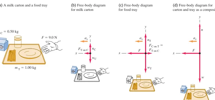
You push a 1.00-kg food tray through the cafeteria line with a con- stant 9.0-N force. The tray pushes on a 0.50-kg carton of milk (Fig.
5.14a). The tray and carton slide on a horizontal surface so greasy that friction can be neglected. Find the acceleration of the tray and carton and the horizontal force that the tray exerts on the carton.
S O L U T I O N
IDENTIFY and SET UP:Ourtwotarget variables are the accelera- tion of the tray–carton system and the force of the tray on the car- ton. We’ll use Newton’s second law to get two equations, one for each target variable. We set up and solve the problem in two ways.
Method 1:We treat the milk carton (mass ) and tray (mass ) as separate bodies, each with its own free-body diagram (Figs. 5.14b and 5.14c). The force F that you exert on the tray doesn’t appear in the free-body diagram for the carton, which is accelerated by the force (of magnitude ) exerted on it by the tray. By Newton’s third law, the carton exerts a force of equal mag- nitude on the tray: FC on T = FT on C.We take the acceleration to
FT on C mT
mC
be in the positive x-direction; both the tray and milk carton move with the same x-acceleration
Method 2:We treat the tray and milk carton as a composite
body of mass (Fig. 5.14d). The only
horizontal force acting on this body is the force Fthat you exert.
The forces and don’t come into play because they’re internalto this composite body, and Newton’s second law tells us that only external forces affect a body’s acceleration (see Section 4.3). To find the magnitude we’ll again apply Newton’s second law to the carton, as in Method 1.
EXECUTE:Method 1:Thex-component equations of Newton’s sec- ond law are
These are two simultaneous equations for the two target variables and FT on C.(Two equations are all we need, which means that ax
Carton: aFx = FT on C = mCax
Tray: aFx = F - FC on T = F - FT on C = mTax FT on C
FC on T FT on C
m = mT + mC= 1.50 kg ax.
the y-components don’t play a role in this example.) An easy way to solve the two equations for is to add them; this eliminates
giving
and
Substituting this value into the carton equation gives
Method 2:The x-component of Newton’s second law for the composite body of mass mis
aFx = F = max
FT on C = mCax = 10.50 kg216.0 m>s22 = 3.0 N ax = F
mT + mC = 9.0 N
1.00 kg+ 0.50 kg = 6.0 m>s2 = 0.61g F = mTax + mCax = 1mT + mC2ax
FT on C,
ax
5.2 Using Newton’s Second Law: Dynamics of Particles 145
The acceleration of this composite body is
Then, looking at the milk carton by itself, we see that to give it an acceleration of requires that the tray exert a force
EVALUATE:The answers are the same with both methods. To check the answers, note that there are different forces on the two sides of the tray: on the right and on the left.
The net horizontal force on the tray is
exactly enough to accelerate a 1.00-kg tray at .
Treating two bodies as a single, composite body works onlyif the two bodies have the same magnitude anddirection of accelera- tion. If the accelerations are different we must treat the two bodies separately, as in the next example.
6.0 m>s2
F - FC on T = 6.0 N, FC on T = 3.0 N
F = 9.0 N
FT on C = mCax = 10.50 kg216.0 m>s22 = 3.0 N 6.0 m>s2
ax = F
m = 9.0 N
1.50 kg = 6.0 m>s2 (a) A milk carton and a food tray (b) Free-body diagram
for milk carton
(c) Free-body diagram for food tray
(d) Free-body diagram for carton and tray as a composite body
y
F ax
x
w n
F
FC on T 5 FT on C y
x
wT nT ax FT on C
ax y
x
wC nC
mT 5 1.00 kg
F 5 9.0 N mC 5 0.50 kg
5.14 Pushing a food tray and milk carton in the cafeteria line.
Example 5.12
Two bodies with the same magnitude of acceleration
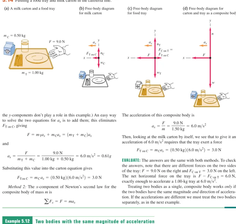
Figure 5.15a shows an air-track glider with mass moving on a level, frictionless air track in the physics lab. The glider is con- nected to a lab weight with mass by a light, flexible, non- stretching string that passes over a stationary, frictionless pulley.
Find the acceleration of each body and the tension in the string.
S O L U T I O N
IDENTIFY and SET UP:The glider and weight are accelerating, so again we must use Newton’s second law. Our three target vari- ables are the tension Tin the string and the accelerations of the two bodies.
The two bodies move in different directions—one horizontal, one vertical—so we can’t consider them together as we did the bodies in Example 5.11. Figures 5.15b and 5.15c show our free-body diagrams and coordinate systems. It’s convenient to have both bodies accelerate in the positive axis directions,
m2
m1
(a) Apparatus (b) Free-body
diagram for glider
(c) Free-body diagram for weight
m2 m1
5.15 (a)The situation. (b), (c)Our free-body diagrams.
Continued
so we chose the positive y-direction for the lab weight to be downward.
We consider the string to be massless and to slide over the pul- ley without friction, so the tension T in the string is the same throughout and it applies a force of the same magnitude Tto each body. (You may want to review Conceptual Example 4.10, in which we discussed the tension force exerted by a massless string.) The weights are and
While the directionsof the two accelerations are different, their magnitudes are the same. (That’s because the string doesn’t stretch, so the two bodies must move equal distances in equal times and their speeds at any instant must be equal. When the speeds change, they change at the same rate, so the accelerations of the two bodies must have the same magnitude a.) We can express this relationship as , which means that we have only twotarget variables: aand the tension T.
What results do we expect? If (or, approximately, for much less than ) the lab weight will fall freely with acceler- ationg, and the tension in the string will be zero. For (or, approximately, for much less than ) we expect zero acceler- ation and zero tension.
EXECUTE:Newton’s second law gives
(There are no forces on the lab weight in the x-direction.) In these equations we’ve used (the glider doesn’t accelerate verti- cally) and a1x = a2y = a.
a1y = 0
Lab weight: aFy = m2g + 1-T2 = m2a2y = m2a Glider: aFy = n + 1-m1g2 = m1a1y = 0 Glider: aFx = T= m1a1x = m1a
m1 m2
m2 = 0 m2
m1
m1 = 0 a1x = a2y = a m2g.
m1g
The x-equation for the glider and the equation for the lab weight give us two simultaneous equations for Tanda:
We add the two equations to eliminate T, giving
and so the magnitude of each body’s acceleration is
Substituting this back into the glider equation , we get
EVALUATE:The acceleration is in general less than g, as you might expect; the string tension keeps the lab weight from falling freely.
The tension Tisnotequal to the weight of the lab weight, but islessby a factor of If T wereequal to then the lab weight would be in equilibrium, and it isn’t.
As predicted, the acceleration is equal to g for and equal to zero for , and for either or .
CAUTION Tension and weight may not be equal It’s a common mistake to assume that if an object is attached to a vertical string, the string tension must be equal to the object’s weight. That was the case in Example 5.5, where the acceleration was zero, but it’s not the case in this example! The only safe approach is alwaysto treat the tension as a variable, as we did here. ❙
m2 = 0 m1 = 0
T= 0 m2 = 0
m1 = 0 m2g, m1>1m1 + m22.
m2g T= m1m2
m1 + m2g
T= m1a a = m2
m1 + m2g
m2g = m1a + m2a = 1m1 + m22a Lab weight: m2g - T= m2a Glider:
T= m1a
Test Your Understanding of Section 5.2 Suppose you hold the glider in Example 5.12 so that it and the weight are initially at rest. You give the glider a push to the left in Fig. 5.15a and then release it. The string remains taut as the glider moves to the left, comes instantaneously to rest, then moves to the right. At the instant the glider has zero velocity, what is the tension in the string? (i) greater than in Example 5.12; (ii) the same as in Example 5.12; (iii) less than in Example 5.12, but greater than zero; (iv) zero.❙
5.3 Frictional Forces
We’ve seen several problems where a body rests or slides on a surface that exerts forces on the body. Whenever two bodies interact by direct contact (touching) of their surfaces, we describe the interaction in terms of contact forces. The normal force is one example of a contact force; in this section we’ll look in detail at another contact force, the force of friction.
Friction is important in many aspects of everyday life. The oil in a car engine minimizes friction between moving parts, but without friction between the tires and the road we couldn’t drive or turn the car. Air drag—the frictional force exerted by the air on a body moving through it—decreases automotive fuel econ- omy but makes parachutes work. Without friction, nails would pull out, light bulbs would unscrew effortlessly, and ice hockey would be hopeless (Fig. 5.16).
Kinetic and Static Friction
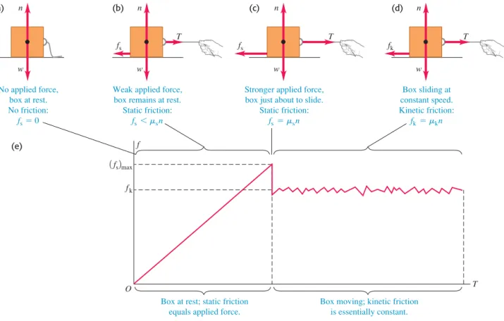
When you try to slide a heavy box of books across the floor, the box doesn’t move at all unless you push with a certain minimum force. Then the box starts moving, and you can usually keep it moving with less force than you needed to
5.16 The sport of ice hockey depends onhaving the right amount of friction between a player’s skates and the ice. If there were too much friction, the players would move too slowly; if there were too little friction, they would fall over.
PhET: Lunar Lander ActivPhysics 2.1.5:Car Race ActivPhysics 2.2:Lifting a Crate ActivPhysics 2.3:Lowering a Crate ActivPhysics 2.4:Rocket Blasts Off ActivPhysics 2.5:Modified Atwood Machine
get it started. If you take some of the books out, you need less force than before to get it started or keep it moving. What general statements can we make about this behavior?
First, when a body rests or slides on a surface, we can think of the surface as exerting a single contact force on the body, with force components perpendicular and parallel to the surface (Fig. 5.17). The perpendicular component vector is the normal force, denoted by The component vector parallel to the surface (and perpendicular to is the friction force, denoted by If the surface is friction- less, then is zero but there is still a normal force. (Frictionless surfaces are an unattainable idealization, like a massless rope. But we can approximate a surface as frictionless if the effects of friction are negligibly small.) The direction of the friction force is always such as to oppose relative motion of the two surfaces.
The kind of friction that acts when a body slides over a surface is called a
kinetic friction forceThe adjective “kinetic” and the subscript “k” remind us that the two surfaces are moving relative to each other. The magnitude of the kinetic friction force usually increases when the normal force increases. This is why it takes more force to slide a box across the floor when it’s