An Assessment of the Angular Spectrum Method for the Propagation of Ultrasound
By
Taylor Glenn Miller
A thesis submitted to the faculty of The University of Mississippi in partial fulfillment of the requirements of the Sally McDonnell Barksdale Honors College.
Oxford May 2015
Approved by
__________________________________
Advisor: Dr. Joel Mobley
__________________________________
Reader: Dr. Joseph Gladden
__________________________________
Reader: Dr. Cecille Labuda
ACKNOWLEDGEMENT
I would like to thank Dr. Joel Mobley for inviting me to the Biomedical Research Group at the National Center for Physical Acoustics at the University of Mississippi and for all the help that he has given me completing my study and writing this thesis. I cannot count the numerous instances during which he has taken time from his busy schedule to help me understand the concepts and processes critical to this project. I would also like to thank the other members of the Biomedical Research Group who have been a constant source of support. I would also like to Dr. Cecille Labuda and Dr. Joseph Gladden for taking the time to read my thesis. Of course, thanks to the Sally McDonnell Barksdale Honors College for motivating me to undertake this endeavor. Last but not least, thanks to Najat Ahmad Al-Sherri. While I have never spoken to her, her thesis has been a great help in seeing how an honors thesis should be structured.
ii
ABSTRACT
Taylor Miller: An Assessment of the Angular Spectrum Method for the Propagation of Ultrasound
The purpose of this project is to investigate the limitations of the angular spectrum method when it is applied to the propagation of acoustic waves in the ultrasonic frequency waves. In this experiment, broadband acoustic waves at ultrasonic frequencies were propagated through a water bath. Ten planar scans perpendicular to the direction of the wave propagation were taken at 10 different distances from the transducer. These scans recorded the pressure field data at each plane. The angular spectrum method was applied to this data, and used to predict the pressure field data at the other planes. Comparison between this predicted data and the original data revealed that the angular spectrum method is best used when trying to predict the field at planes further away from the source than the experimental data and it is best applied on experimental data taken near the source, rather than further away.
iii
TABLE OF CONTENTS
ACKNOWLEDGEMENTS………..ii
ABSTRACT………..iii
TABLE OF CONTENTS………..iv
LIST OF FIGURES………..v
LIST OF ABREVIATIONS………..vi
INTRODUCTION……….1
THEORY………3
MATERIALS AND METHOD..………17
RESULTS………27
DISCUSSION………49
CONCLUSION……….52
REFERENCES………..53
APPENDIX A………55
APPENDIX B………58
List of Figures Figure 1: An illustration of longitudinal waves
Figure 2: An illustration of the acoustic spectrum
Figure 3: A graph depicting a signal and its temporal Fourier transform Figure 4: A graph depicting a signal and its spatial Fourier transform
Figure 5: Flowchart depicting the process that the Angular Spectrum method entails Figure 6: Diagram of the internal structure of an ultrasound transducer
Figure 7: Diagram of the experimental setup
Figure 8: Image of transducer and hydrophone in the water bath Figure 9: Image of the motorized gantry
Figure 10: Diagram depicting scan plan positions
Figures 11 – 19: Graphs of experimental data and the propagations for absolute depth of 61.81 mm
Figures 20 – 29: Graphs that depict all of the propagations and experimental data organized by absolute depth and then relative depth.
v
LIST OF ABBREVIATIONS
DFT Discrete Fourier Transform
INTRODUCTION
The angular spectrum method is a technique for calculating a wave field in one plane given its values in another plane parallel to the original. The goal of this study is to analyze the limits of the angular spectrum method as applied to real data that has been measured in various parallel planes. Specifically, data will be presented in order to compare the accuracy of backward propagation (opposite the direction of wave travel) to forward propagation (in the direction of wave travel) and from which planes the most accurate predictions were created. In this work, an ultrasonic transducer with a planar aperture, which was submerged in a water bath, was used to produce the ultrasonic field. A transducer is any device capable of converting one energy type to another. The transducer used in this experiment contains a piezoelectric crystal that converts an electric signal into mechanical (ultrasound) vibrations, which are the source of ultrasonic waves.
A small, point-like transducer known as a hydrophone was used to measure the ultrasonic field point-by-point in the plane
A novel aspect of this work is that a broadband pulse was used to generate the field analyzed in this experiment. A broadband pulse is a pulse which is short (narrow in time), but is composed of many frequencies. Each frequency represents a continuous sine wave, which is not restricted in time. Using this type of data takes more computational time to analyze, but it provides data on multiple frequencies with a single data acquisition. A temporal Fourier transform was used to extract the pressure data of a single frequency out of the original pulse. This way, the field at a particular frequency could be extracted from the waveform captured at each position
1
Using this set up, ten different sets of x-y transverse plane data along the z-axis (the propagation axis) were recorded. Using this calculated z-position, the angular spectrum method was applied to each plane in order to propagate it to the other planes. Qualitative comparisons of the propagated data to the experimental data were then to evaluate our hypotheses on the limits of the angular spectrum method.
The hypothesis of this study is that backward and forward propagation are equally accurate techniques, and that propagations are most accurate when done between planes that are closer together.
In the chapters that follow, the theory is presented, followed by the description of the experimental setup and methods. Then the data is presented along with comparison with the angular spectrum methods. This is followed by a discussion and the conclusions of the study.
2
THEORY Sound
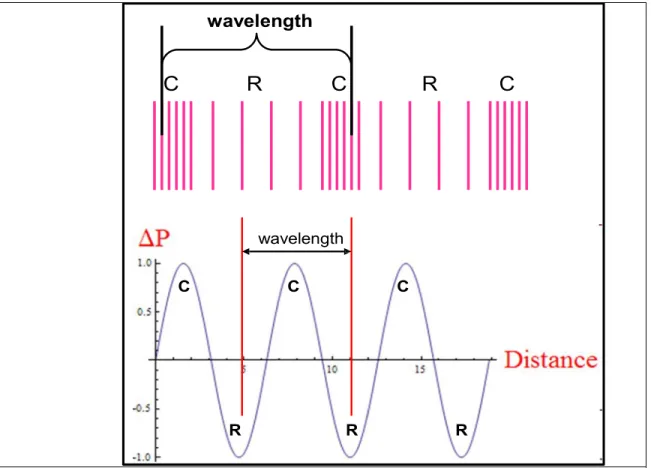
Sound waves are mechanical waves which are motional disturbances that propagate through a material system (fluids and solids) and are caused by vibrating bodies. Sound waves, when transmitting though fluids such as water, are purely longitudinal (Figure 1) meaning that they transmit via compressions and rarefactions (pressure fluctuations) of the medium along the direction of propagation (Laugier, 2011). The wave transmits energy between the particles that make up the material. While the sound wave travels through the medium, the particles of the medium oscillate about their equilibrium positions. So, when a sound wave travels, it is the disturbances (compressions and rarefactions) that are propagating, not the particles themselves (Glickstein, 1960).
3
Figure 1: These are two different representations of longitudinal waves. They each depict the areas of compression (C) and rarefaction (R) which characterize the wave. The compression areas have higher amplitude than the higher rarefaction areas, due to the higher particle density. Modified from
http://www.genesis.net.au/~ajs/projects/medical_physics/ultrasound/index.html
4
The speed of a sound wave (c), as with any other wave, has a direct relationship with frequency (ν) and wavelength (λ) given by,
𝑐𝑐=𝜈𝜈𝜈𝜈
This equation can also be written in terms of the angular frequency (ω) and wave number (k) where, 𝜔𝜔= 2𝜋𝜋𝜈𝜈,𝑘𝑘=2𝜋𝜋𝜆𝜆
as
𝑐𝑐=𝜔𝜔 𝑘𝑘
The speed of sound in a fluid is dependent on the bulk modulus (β) and density (ρ) of the fluid in question as given by
𝑐𝑐=�𝛽𝛽 𝜌𝜌.
The bulk modulus of water is much higher than that of air, so the speed of sound in water (1.482 mm/μs at 20⁰C) is much higher than that of air (0.343 mm/μs at 20⁰C). The speed of sound is temperature dependent, which is unique to the material in which the sound wave is propagating (Laugier, 2011).
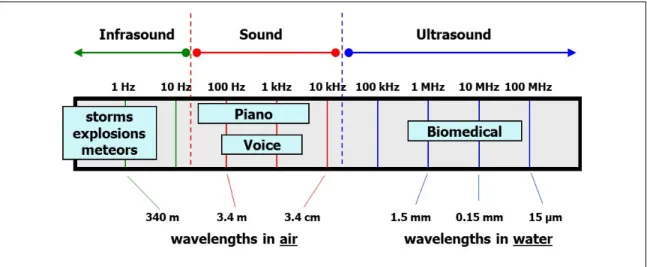
Acoustic waves are classified by their frequency (Figure 2). The range of human hearing is between 20 Hz and 20,000 Hz. All the frequencies below that range are labeled as infrasonic and all the ones that are above that range are labeled as ultrasonic. Ultrasound has a wavelength of only a few millimeters or less, which gives it many applications in materials testing as well as biomedical diagnostics and therapy (Glickstein, 1960).
5
Figure 2: The acoustic spectrum. Humans can hear frequencies between 20 Hz and 20 kHz. All frequencies below 20 Hz are classified as infrasound and all frequencies above 20 kHz are classified as Ultrasound. Courtesy of Joel Mobley
6
Fourier Analysis
Fourier analysis is method by which a function is represented in terms of its component frequencies, where each frequency is associated with a sine wave. Periodic waves are described by the Fourier series which is given by
𝑓𝑓(𝑡𝑡) = � 𝑐𝑐𝑛𝑛𝑒𝑒𝑖𝑖2𝜋𝜋𝑛𝑛𝜋𝜋/𝑇𝑇
∞
𝑛𝑛=−∞
where 𝑡𝑡 is time, 𝑇𝑇 is period, 𝑛𝑛 is an integer, and 𝑐𝑐𝑛𝑛 is the Fourier coefficient given by
𝑐𝑐𝑛𝑛=1
𝑇𝑇 � 𝑒𝑒−2𝜋𝜋𝑛𝑛𝜋𝜋/𝑇𝑇𝑓𝑓(𝑡𝑡)𝑑𝑑𝑡𝑡
𝑇𝑇 0
.
In this way, the function 𝑓𝑓(𝑡𝑡) is expressed as an infinite sum of sine waves with weight given by the coefficients 𝑐𝑐𝑛𝑛. Each of these sine waves is characterized by a frequency (given by 𝜈𝜈=𝑛𝑛/𝑇𝑇) and is a harmonic (multiple) of a fundamental frequency (Osgood, 2008). In order to apply Fourier analysis to a non-periodic function one must use a Fourier transform. The Fourier transform is similar to a Fourier series, but with the period of repetition essentially taken to infinity. The discrete variable 𝑛𝑛 𝑇𝑇⁄ can be replaced with a continuous variable since,
2𝜋𝜋𝑛𝑛 𝑇𝑇 → 𝜔𝜔 So the transform is expressed as
𝑓𝑓̂(𝜔𝜔) = � 𝑒𝑒−𝑖𝑖𝑖𝑖𝜋𝜋𝑓𝑓(𝑡𝑡)𝑑𝑑𝑡𝑡
∞
−∞
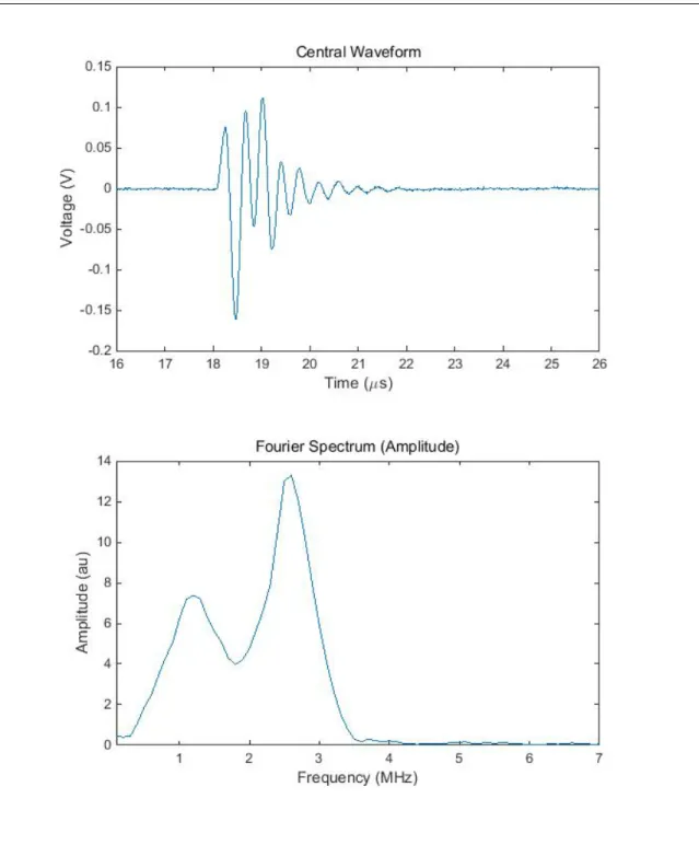
Where 𝑓𝑓(𝑡𝑡) is the signal captured at a point as the wave passes (Osgood, 2008). This is the temporal Fourier transform. The function 𝑓𝑓̂(𝜔𝜔) represents the amplitudes of continuous waves
7
of frequency ω. This function is known as the temporal spectrum of the signal 𝑓𝑓(𝑡𝑡), shown in Figure 3. It is also possible to recover the original function by taking the inverse Fourier transform, which is given by
𝑓𝑓(𝑡𝑡) = 1
2𝜋𝜋 � 𝑒𝑒𝑖𝑖𝑖𝑖𝜋𝜋𝑓𝑓̂(𝜔𝜔)𝑑𝑑𝜔𝜔
∞
−∞
Taken together, the Fourier transform and its inverse (i.e. spectrum) are said to form a Fourier transform pair (Osgood, 2008).
8
Figure 3: The first image is the signal and the second image is the temporal Fourier transform.
The curve in the transform indicates the strength of each sine function that the signal is composed of. This signal is primarily composed of waves with frequency between approximately 1.3 MHz and 3.5 MHz.
9
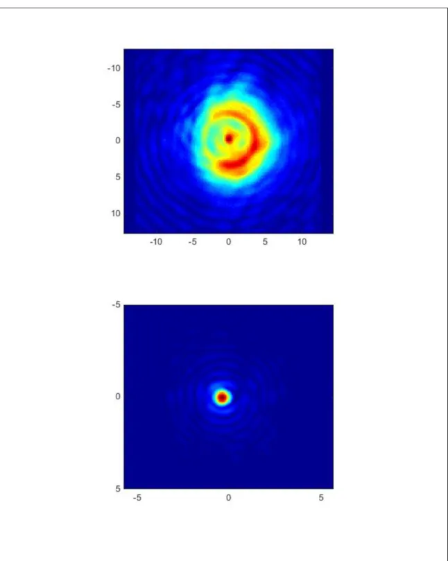
The transform can also be applied to spatial patterns via the 2-dimensional variant of the transform, shown in Figure 4. In this case, the transform pair is defined as below,
𝑓𝑓̂�𝑘𝑘𝑥𝑥,𝑘𝑘𝑦𝑦�= � 𝑒𝑒−𝑖𝑖𝑘𝑘𝑥𝑥𝑥𝑥𝑒𝑒−𝑖𝑖𝑘𝑘𝑦𝑦𝑦𝑦𝑓𝑓(𝑥𝑥,𝑦𝑦)𝑑𝑑𝑥𝑥𝑑𝑑𝑦𝑦
∞
−∞
𝑓𝑓(𝑥𝑥,𝑦𝑦) = 1
(2𝜋𝜋)2 � 𝑒𝑒𝑖𝑖𝑘𝑘𝑥𝑥𝑥𝑥𝑒𝑒𝑖𝑖𝑘𝑘𝑥𝑥𝑥𝑥𝑓𝑓̂�𝑘𝑘𝑥𝑥,𝑘𝑘𝑦𝑦�𝑑𝑑𝑘𝑘𝑥𝑥𝑑𝑑𝑘𝑘𝑦𝑦
∞
−∞
where 𝑘𝑘 is the wave number and 𝑘𝑘𝑥𝑥, 𝑘𝑘𝑦𝑦, and 𝑘𝑘𝑧𝑧 are the components of the wave vector 𝑘𝑘�⃗
(Wilcock, 2014).
10
Figure 4: The first image is the signal and the second image is the spatial Fourier transform. The red indicates higher amplitudes and blue indicates an amplitude of zero. The spatial Fourier transform has a high focus in the center where there are lower wave vectors
11
Angular Spectrum
The angular spectrum method is a technique for propagating an acoustic field by first representing it as a superposition of plane waves, propagating those waves and superimposing them. The technique begins by using the 2-dimensional spatial Fourier transform to calculate the angular spectrum of the field in a plane. This is done on an x-y transverse plane where propagation is assumed to occur along the z-axis. Let the ultrasonic field in a source plane at a position 𝑧𝑧0 be 𝐴𝐴(𝑥𝑥,𝑦𝑦,𝑧𝑧0) then the angular spectrum, 𝑈𝑈��𝑘𝑘𝑥𝑥,𝑘𝑘𝑦𝑦,𝑧𝑧0�, is given by the spatial 2-Dimensional transform,
𝑈𝑈��𝑘𝑘𝑥𝑥,𝑘𝑘𝑦𝑦,𝑧𝑧0�= � 𝐴𝐴(𝑥𝑥,𝑦𝑦,𝑧𝑧0)𝑒𝑒−𝑖𝑖𝑘𝑘𝑥𝑥𝑥𝑥𝑒𝑒−𝑖𝑖𝑘𝑘𝑦𝑦𝑦𝑦𝑑𝑑𝑥𝑥𝑑𝑑𝑦𝑦
∞
−∞
The inverse of this transform is
𝐴𝐴(𝑥𝑥,𝑦𝑦,𝑧𝑧0) = 1
(2𝜋𝜋)2 � 𝑈𝑈��𝑘𝑘𝑥𝑥,𝑘𝑘𝑦𝑦,𝑧𝑧0�𝑒𝑒−𝑖𝑖𝑘𝑘𝑥𝑥𝑥𝑥𝑒𝑒−𝑖𝑖𝑘𝑘𝑦𝑦𝑦𝑦𝑑𝑑𝑘𝑘𝑥𝑥𝑑𝑑𝑘𝑘𝑦𝑦
∞
−∞
The next step is to propagate the transform in order to take it from the 𝑧𝑧0 plane to the 𝑧𝑧 plane.
This begins with the wave equation for a monochromatic plane wave in linear, elastic, lossless media
𝛻𝛻2𝛹𝛹= 1 𝑐𝑐2
𝜕𝜕2𝛹𝛹
𝜕𝜕𝑡𝑡2
One way to solve this equation is to write 𝛹𝛹 as a product of a temporal function and a spatial function
𝛹𝛹(𝑟𝑟,𝑡𝑡) =𝐴𝐴(𝑟𝑟)𝑇𝑇(𝑡𝑡)
12
One can substitute this equation into the original wave equation and then separate it so that one side is entirely spatial and the other is entirely temporal to obtain
1
𝐴𝐴 ∇2𝐴𝐴= 1 𝑐𝑐2𝑇𝑇
𝜕𝜕2𝑇𝑇
𝜕𝜕𝑡𝑡2 =𝑐𝑐𝑜𝑜𝑛𝑛𝑜𝑜𝑡𝑡=−𝑘𝑘2
Since the variables on either side of the equation are independent of each other, they must both be equal to a constant, which is defined as −𝑘𝑘2 (the negative of the wave number of the material squared). This allows separation of the original equation into two independent equations: a temporal equation and a spatial equation (Hollman, 1995).
The temporal part of this equation is a simple second order partial differential equation solved by first separating the derivative and constant terms to get
𝑑𝑑2𝑇𝑇
𝑑𝑑𝑡𝑡2 =−𝑘𝑘2𝑐𝑐2𝑇𝑇.
Assuming that the wave is monochromatic (composed of a single frequency), we can substitute 𝜔𝜔=𝑘𝑘𝑐𝑐 giving
𝑑𝑑2𝑇𝑇
𝑑𝑑𝑡𝑡2 =−𝜔𝜔2𝑇𝑇 The solution to which is the exponential function
𝑇𝑇=𝑇𝑇0𝑒𝑒𝑖𝑖𝑖𝑖𝜋𝜋
If the spatial part is rearranged, then that equation becomes
(𝛻𝛻2+𝑘𝑘2)𝐴𝐴(𝑥𝑥,𝑦𝑦,𝑧𝑧0) = 0 which is the Helmholtz equation.
13
When the time invariant operator of the Helmoltz equation (i.e. 𝛻𝛻2+𝑘𝑘2) is applied to the inverse Fourier transform of 𝐴𝐴 then it becomes
(∇2+𝑘𝑘2)𝐴𝐴(𝑥𝑥,𝑦𝑦,𝑧𝑧0) =(∇2+𝑘𝑘2)
4𝜋𝜋2 � 𝑈𝑈��𝑘𝑘𝑥𝑥,𝑘𝑘𝑦𝑦,𝑧𝑧0�𝑒𝑒−𝑖𝑖𝑘𝑘𝑥𝑥𝑥𝑥𝑒𝑒−𝑖𝑖𝑘𝑘𝑦𝑦𝑦𝑦𝑑𝑑𝑘𝑘𝑥𝑥𝑑𝑑𝑘𝑘𝑦𝑦
∞
−∞
The left side of this equation is equivalent to zero, and we can bring the operator on the right side into the integral since 𝛻𝛻 only depends on the spatial coordinates and 𝑘𝑘2 is a constant.
0 = 1
4𝜋𝜋2 �(∇2+𝑘𝑘2)𝑈𝑈�𝑘𝑘𝑥𝑥,𝑘𝑘𝑦𝑦,𝑧𝑧0�𝑒𝑒−𝑖𝑖𝑘𝑘𝑥𝑥𝑥𝑥𝑒𝑒−𝑖𝑖𝑘𝑘𝑦𝑦𝑦𝑦𝑑𝑑𝑘𝑘𝑥𝑥𝑑𝑑𝑘𝑘𝑦𝑦
∞
−∞
.
Applying the operator to the integrand and using the substitution
𝑘𝑘𝑧𝑧2=𝑘𝑘2− 𝑘𝑘𝑥𝑥2− 𝑘𝑘𝑦𝑦2, the equation becomes
0 = 1
4𝜋𝜋2 � �∂2
𝜕𝜕𝑧𝑧2+𝑘𝑘𝑧𝑧2� 𝑈𝑈��𝑘𝑘𝑥𝑥,𝑘𝑘𝑦𝑦,𝑧𝑧0�𝑒𝑒−𝑖𝑖𝑘𝑘𝑥𝑥𝑥𝑥𝑒𝑒−𝑖𝑖𝑘𝑘𝑦𝑦𝑦𝑦𝑑𝑑𝑘𝑘𝑥𝑥𝑑𝑑𝑘𝑘𝑦𝑦
∞
−∞
.
For an inverse Fourier transform to be zero the transforming equation must also be zero, so this leaves a differential equation
0 =�∂2
𝜕𝜕𝑧𝑧2+𝑘𝑘𝑧𝑧2� 𝑈𝑈��𝑘𝑘𝑥𝑥,𝑘𝑘𝑦𝑦,𝑧𝑧0�
which is solved by the monochromatic plane wave
𝑈𝑈��𝑘𝑘𝑥𝑥,𝑘𝑘𝑦𝑦,𝑧𝑧�=𝑈𝑈��𝑘𝑘𝑥𝑥,𝑘𝑘𝑦𝑦,𝑧𝑧0�𝑒𝑒𝑖𝑖𝑘𝑘𝑧𝑧(𝑧𝑧−𝑧𝑧0).
14
This is how the angular spectrum for the plane at position 𝑧𝑧 is calculated and therefore is where propagation occurs. The final step is using an inverse Fourier transform to obtain the pressure data at the plane 𝑧𝑧
𝐴𝐴(𝑥𝑥,𝑦𝑦,𝑧𝑧) = 1
4𝜋𝜋2 � 𝑈𝑈��𝑘𝑘𝑥𝑥,𝑘𝑘𝑦𝑦,𝑧𝑧�𝑒𝑒−𝑖𝑖𝑘𝑘𝑥𝑥𝑥𝑥𝑒𝑒−𝑖𝑖𝑘𝑘𝑦𝑦𝑦𝑦𝑑𝑑𝑘𝑘𝑥𝑥𝑑𝑑𝑘𝑘𝑦𝑦
∞
−∞
.
The full equation of the process is
𝐴𝐴(𝑥𝑥,𝑦𝑦,𝑧𝑧) = 1
4𝜋𝜋2 � � � 𝐴𝐴(𝑥𝑥,𝑦𝑦,𝑧𝑧0)𝑒𝑒−𝑖𝑖𝑘𝑘𝑥𝑥𝑥𝑥𝑒𝑒−𝑖𝑖𝑘𝑘𝑦𝑦𝑦𝑦𝑑𝑑𝑥𝑥𝑑𝑑𝑦𝑦
∞
−∞
� 𝑒𝑒𝑖𝑖𝑘𝑘𝑧𝑧(𝑧𝑧−𝑧𝑧0)𝑒𝑒−𝑖𝑖𝑘𝑘𝑥𝑥𝑥𝑥𝑒𝑒−𝑖𝑖𝑘𝑘𝑦𝑦𝑦𝑦𝑑𝑑𝑘𝑘𝑥𝑥𝑑𝑑𝑘𝑘𝑦𝑦
∞
−∞
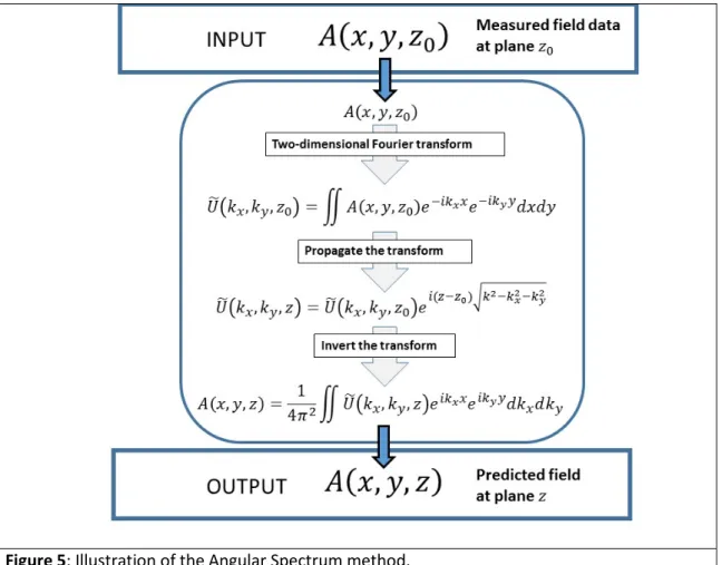
Ultimately, the Angular Spectrum method starts with an input of x-y pressure data. It then takes the spatial 2-D Fourier Transform of that data which finds the angular spectrum of plane waves at this plane. Next, it propagates that data and finds the angular spectrum at the destination plane.
Finally, a 2-D inverse transform is performed to yield the pressure data in the new plane (Hollman, 1995) (Figure 5).
15
Figure 5: Illustration of the Angular Spectrum method.
16
MATERIALS AND METHOD Setup
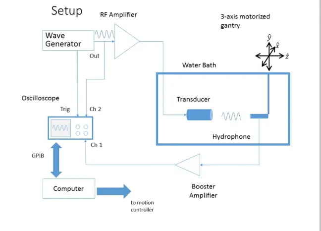
The experimental set up begins with a waveform generator (Wavetek 100 MHz synthesized arbitrary waveform generator model 395) which create the required signal to generate the source wave. This is a low power signal, so it is sent through a RF amplifier (Amplifier Research model 5OA15), to boost its power to a level that the transducer (Panametrics V306, 2.25MHz, 0.5” diameter) requires. The transducer uses the piezoelectric effect to convert the electrical signal coming from the amplifier to the mechanical vibration launces the ultrasonic wave (Glickstein, 1960) (Figure 6).
Figure 6: Diagram of the internal structure of a typical ultrasound transducer. A high energy signal excites the piezoelectric crystal, which vibrates, producing an acoustic wave. Modified from http://www.genesis.net.au/~ajs/projects/medical_physics/ultrasound/index.html
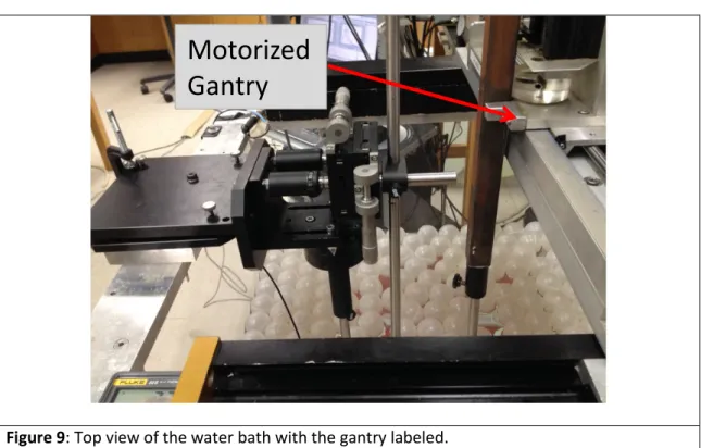
Facing the transducer plane lies the hydrophone (Precision Acoustics LTD Needle Hydrophone). This is the device that, mounted on a 3-axis motorized gantry, collects the pressure data via planar scans (Figure 9). The hydrophone is also piezoelectric and converts the pressure variations of the ultrasonic wave to an electrical signal. The hydrophone signal goes through a
High Energy Electrical Signal
Acoustic Wave
17
preamplifier (Precision Acoustics LTD Hydrophone Booster Amplifier) and is fed to the oscilloscope where it is captured, digitized, and downloaded to the computer. The oscilloscope is triggered by the waveform generator which allows absolute propagation time to be collected.
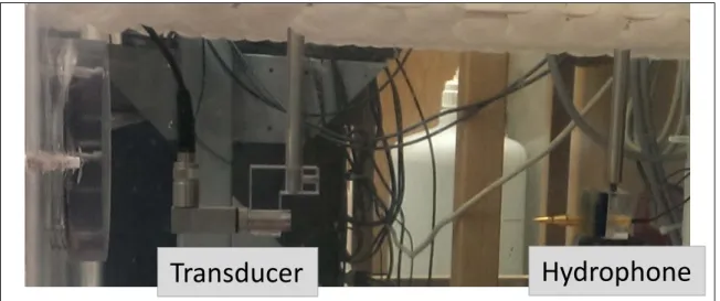
The hydrophone and transducer are both submerged in a water bath (Figure 8). When conducting ultrasound experiments, monitoring the temperature is very important. Since speed of sound changes based on temperature, because the scans used in this experiment lasted several hours, any fluctuations in temperature of the tank water could cause unwanted timing variations across the scan plane. The tank temperature was measured using a thermocouple probe (Fluke 50S K/J Thermometer).
A complete diagram of the experimental setup is shown in Figure 7.
18
Figure 7: This is a diagram of the experimental setup explained above. Arrows indicated direction that the electrical signal travels.
19
Figure 8: Transducer and Hydrophone submerged in the water bath.
Figure 9: Top view of the water bath with the gantry labeled.
Transducer Hydrophone
Motorized Gantry
20
Data Acquisition
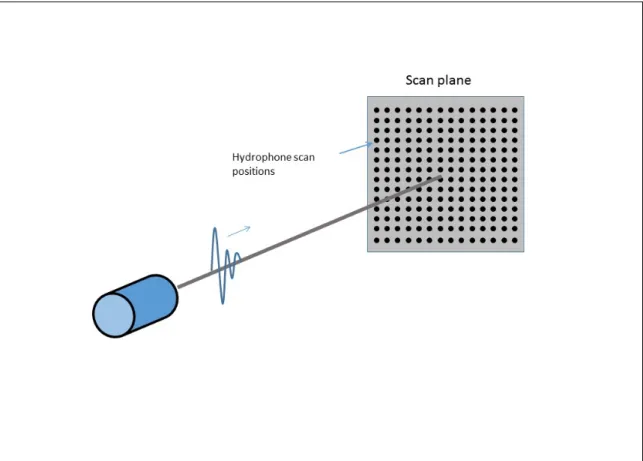
For the experimental measurements, the waveform generator was set to output a single cycle of 2.25 MHz sine wave. The amplified pulse excited the transducer and the resulting pulse propagates through the water and is sampled by the hydrophone. The plane scans were accomplished by moving the hydrophone via the motorized gantry which is controlled with a custom written program running in the MATLAB environment on the computer. Stepper motors were used to drive the sleds of the motion control system which, in turn, moved the hydrophone in 0.1524 mm steps across the scan plane, which was parallel to the propagation axis. Plane scans were square with dimensions 25 mm x 25 mm with 167 x 167 points. The scans started at the bottom-right point and then moved along the y-axis until reaching the bottom-left point.
Afterwards it moved up one point in the x-axis before moving left-to-right along the y-axis. This process repeated until the entire plane was scanned (Figure 10).
21
Figure 10: As the signal cross the scan plane, the hydrophone records it at each of the scan positions, as depicted above.
Whenever the hydrophone is further from the center of the scan plane, in general, the amplitude of the pressure field (and therefore the electrical signal) captured by the oscilloscope decreases. The size of the signal can vary greatly over the scan plane. To optimize the oscilloscope setting for a given signal, an autoscaling routine is included in the code which controls the acquisition. At each data point, several waveforms were generated and averaged in order to decrease random noise. This averaged data is what was finally recorded by the computer.
Between scans the transducer was moved to a new plane using the motorized system.
The position of the hydrophone was then adjusted to align with the center for the ultrasonic field so the origin point of the scan was at the center of the field. Additional adjustments had to be made before data could be collected. A review of initial scans revealed that the signals from the
22
right half of the scan plane were arriving before those from the left half. Using a rotating stage, the transducer orientation was adjusted to correct for this issue.
All scan distances were originally recorded in reference to a “0” plane, which was just under the hood of the transducer mount. The first scan was done 5 mm from this position and then the transducer was moved distal by another 10 mm for each subsequent scan until 10 total scans were acquired. This range includes both the near and far field regions, including the focal zone which lies in between.
23
Data Analysis
This study is concerned with analyzing the accuracy of the angular spectrum method in using acquired data and computationally map the field to a new plane. To precisely identify the scan plane, the time delay from the trigger to the front of the central signal of the plane scan was determined
Using the temperature readings from the thermocouple, the speed of sound (in mm/μs) for the scan was determined using a well-known empirical relationship (Laugier, 2011). Using the relationship
𝑑𝑑=𝑐𝑐𝑐𝑐
the absolute distance (mm) to the scan planes from the transducer was calculated. These values were then used to define the propagation distances between the various planes. After the distances and speeds of sound were found, a temporal Fourier transform was performed on the data in order to extract the 2.25 MHz frequency component from the broadband signals. The signals were digitally sampled to 2000 points, so a discrete Fourier transform (DFT) was applied to each signal array. The DFT is an approximate method for calculating the Fourier Transform of a discrete (i.e. sampled) data set, and is given by (Roberts, 2003)
𝐴𝐴̂(𝜔𝜔) = � 𝐴𝐴(𝑐𝑐)𝑒𝑒−𝑖𝑖𝜔𝜔𝑛𝑛𝑡𝑡
𝑀𝑀−1
𝑛𝑛=0
where 𝐴𝐴(𝑐𝑐) is the function, 𝑀𝑀 is the number of data points and 𝑛𝑛 is an integer. The 𝜔𝜔𝑛𝑛 is given by,
𝜔𝜔𝑛𝑛 = 2𝜋𝜋𝑛𝑛 𝑀𝑀∆𝑐𝑐. The inverse of this transform is (Roberts, 2003)
24
𝐴𝐴(𝑐𝑐) = 1
𝑀𝑀 � 𝐴𝐴̂(𝜔𝜔)𝑒𝑒𝑖𝑖𝜔𝜔𝑛𝑛𝑡𝑡
𝑀𝑀−1 𝑛𝑛=0
.
This technique is applied using a Fast Fourier Transform (FFT), which is an algorithim that greatly reduces the time required to perform a DFT. From each signal, the Fourier coefficient of the frequency of interest is extracted. The coefficients are then used to form a two dimensional image of the field at that frequency. To apply the angular spectrum to this data, the field is embedded in a larger array, whose pixels are initialized to zero. This artificially pushes the edges of the scan farther out which helps avoid certain artifacts associated with the angular spectrum technique.
Thus the 167 x 167 data are embedded into the center of a 512 array
Once the data set has been embedded in the larger space the angular spectrum is applied two dimensional spatial Fourier transform is applied to the data plane. Since that data is discrete the DFT is used. It takes the form (Roberts, 2003)
𝑈𝑈��𝑘𝑘𝑥𝑥,𝑘𝑘𝑦𝑦,𝑧𝑧0�= � � 𝐴𝐴(𝑥𝑥𝑚𝑚,𝑦𝑦𝑛𝑛,𝑧𝑧0)𝑒𝑒−𝑖𝑖𝑘𝑘𝑚𝑚,𝑥𝑥𝑥𝑥𝑚𝑚𝑒𝑒−𝑖𝑖𝑘𝑘𝑛𝑛,𝑦𝑦𝑦𝑦𝑛𝑛
𝑁𝑁2+1
𝑛𝑛=−𝑁𝑁/2 𝑀𝑀2 +1
𝑚𝑚=−𝑀𝑀/2
where
𝑥𝑥𝑚𝑚=𝑚𝑚∆𝑥𝑥 𝑦𝑦𝑛𝑛=𝑛𝑛∆𝑦𝑦 km,x=2πm
M∆x kn,y=2πn N∆y
and ∆𝑥𝑥 and ∆𝑦𝑦 are the respective step sizes and 𝑚𝑚 and 𝑛𝑛 are integers.
The inverse of this transform is used after the wave has been propagated and is of the form (Roberts, 2003)
𝐴𝐴(𝑥𝑥𝑚𝑚,𝑦𝑦𝑛𝑛,𝑧𝑧) = 1
𝑀𝑀𝑀𝑀 � � 𝑈𝑈��𝑘𝑘𝑥𝑥,𝑚𝑚,𝑘𝑘𝑦𝑦,𝑛𝑛,𝑧𝑧�𝑒𝑒𝑖𝑖𝑘𝑘𝑚𝑚,𝑥𝑥𝑥𝑥𝑒𝑒𝑖𝑖𝑘𝑘𝑛𝑛,𝑦𝑦𝑦𝑦
𝑁𝑁2−1
𝑛𝑛=−𝑁𝑁/2 𝑀𝑀2 −1
𝑚𝑚=−𝑀𝑀/2
25
Each data set was propagated to all the planes of the other acquired scans and then an image was produced for each propagation, along with the images of the experimental data itself. A total of 100 images (90 propagations and 10 original data sets) were produced.
26
RESULTS
In this section, both the experimental data collected during the experiment and the propagations made using the angular spectrum are presented. Figures 11 – 19 contain two images each. The top image, marked experimental data, is the experimental data from the plane scan made using the hydrophone. The bottom image is the field propagated with the angular spectrum from another planes experimental data. It is marked with the absolute depth, which is the distance from the hydrophone, and the relative depth, which is difference between the z-position of the destination plane and the z-position of the experimental data (in the angular spectrum equation this is the value of z – z0). The data sets are ordered so that the propagations that are from planes closest to the transducer are presented first and the ones furthest from the transducer are shown last. The relative depth indicates the direction of propagation: a forward propagation has a positive value and a backward propagation has a negative value. The images show millimeters on both axes and the color adds a third dimension to the graph. This is the relative amplitude of the pressure field. The dark blue indicates lowest pressure and the dark red indicates the highest pressure. By comparing the color distribution in the experimental data and that of the propagated data, the accuracy of the angular spectrum method can be evaluated.
In figures 11 – 19, the experimental data and propagations associated with z = 61.81 mm are shown. This is the data that is discussed in depth in the next section. Each figure has two images; one of the experimental data, which is the experimental data and one of a propagation, ordered by relative depth with highest depth first. This allows for the experimental data and the propagation produced through the angular spectrum to be easily compared.
27
Figure 11: The experimental data is on top and the propagation is on bottom. This propagation is forward and from the plane closest to the transducer.
28
Figure 12: The experimental data is on top and the propagation is on bottom. This propagation is forward.
29
Figure 13: The experimental data is on top and the propagation is on bottom. This propagation is forward
30
Figure 14: The experimental data is on top and the propagation is on bottom. This propagation is forward and from the plane closest to the experimental data with being any further from the transducer than the experimental data.
31
Figure 15: The experimental data is on top and the propagation is on bottom. This propagation is backward and from the plane closest to the experimental data, without being any closer to the transducer.
32
Figure 16: The experimental data is on top and the propagation is on bottom. This propagation is backward.
33
Figure 17: The experimental data is on top and the propagation is on bottom. This propagation is backward.
34
Figure 18: The experimental data is on top and the propagation is on bottom. This propagation is backward.
35
Figure 19: The experimental data is on top and the propagation is on bottom. This propagation is backward, and from the plane furthest from the transducer.
36
The remainder of the data (Figures 20 – 29) is presented in 8 tables below. The data is organized by the absolute depth and then the relative depth moving from lowest to highest. The lower the absolute depth the closer the plane is to the transducer. In each set of data, the experimental data is highlighted and marked “E”. Furthermore, the same section of each table will be associated with only one experimental data, meaning that the top left section of each table is propagated from the same set of experimental data. This allows one to see how propagations evolve for different experimental data.
37
Figure 20: The experimental data is highlighted in the top left and marked with an “E” and the rest are propagations to that plane. 𝑧𝑧= 26.82
E
38
Figure 21: The experimental data is highlighted and marked with an “E” and the rest are propagations to that plane. 𝑧𝑧= 31.83
E
39
Figure 22: The experimental data is highlighted and marked with an “E” and the rest are propagations to that plane. 𝑧𝑧= 41.94
E
40
Figure 23: The experimental data is highlighted and marked with an “E” and the rest are propagations to that plane. 𝑧𝑧= 51.83
E
41
Figure 24: The experimental data is highlighted and marked with an “E” and the rest are propagations to that plane. This is also the data in figures 11-19. 𝑧𝑧= 61.81
E
42
Figure 25: The experimental data is highlighted and marked with an “E” and the rest are propagations to that plane. 𝑧𝑧= 71.71
E
43
Figure 26: The experimental data is highlighted and marked with an “E” and the rest are propagations to that plane. 𝑧𝑧= 81.83
E
44
Figure 27: The experimental data is highlighted and marked with an “E” and the rest are propagations to that plane. 𝑧𝑧= 91.91
E
45
Figure 28: The experimental data is highlighted and marked with an “E” and the rest are propagations to that plane. 𝑧𝑧= 101.88
E
46
Figure 29: The experimental data is highlighted and marked with an “E” and the rest are propagations to that plane. 𝑧𝑧= 111.91
E
47
48
DISCUSSION
The data presented in figures 11 - 19 contains four forward propagations and five back propagations. Looking through the data, it is apparent that both types of propagations are able to produce the general shape of the experimental data, i.e. the sharp peak in pressure that gradually fades to zero. However, comparing the last forward propagation (Figure 14) to the first back propagation (Figure 15), It is clear that the forward propagation has a more clear and accurate prediction. It is able to successfully reproduce the egg-shape in the green and teal region of the graph and the oblong red region, even if it is not properly oriented. Most impressively, the forward propagation is able to reproduce the diffraction pattern present in the experimental data. The back propagation, on the other hand, contains significant errors. The most apparent error is the presence of artifacts, square structures that are present throughout the image. They are most present in the boundary between the teal region of the graph and the light blue region. Beyond this, there is also a major error in that there is an orange projection on the outer, bottom edge of the center of the graph that is certainly not present in the original data. This isn’t to say the forward propagation is without error. A close inspection of the 9.98 data (Figure 14) reveals that there are some artifacts even in this plot. All of this reveals that forward propagation is more accurate than backward propagation.
If one considers the theory behind the angular spectrum method the reason for this is straightforward. The method takes a complex wave pattern in a 2-D scan and breaks it down into an angular spectrum of plane waves. Each wave is moved forward or backward in space until it reaches the destination plane. They are then superimposed upon each other to produce the field
49
at this location. One explanation is that more data is available for forward propagation than for backward propagation. As the wave moves in space, it spreads out and occupies a greater area.
Even though most of the field is still near the axis, some of it has left the detection region, so there is a loss in accuracy. Another large difference is that a backward propagation has to make a prediction on a plane that contains more information (more of the original waveform) than the plane that is being propagated from (the source plane). It follows that there would be a loss of clarity in making this prediction, since some of the plane waves that make up the destination plane would have left the source plane.
Looking through the rest of the data supports this conclusion. As the relative distance increases, i.e. moving the source plane further from the destination plane and closer to the transducer, the image begins losing many of the artifacts and gains contours. In particular the propagation in Figure 11 with relative depth 34.99 mm has incredible clarity. However there is some trade off here. While the core of the propagation is most similar to the core of the original data in Figure 11’s propagation, the teal area is not as accurate as it is in the propagation in Figure 14 with relative depth 9.98 mm. The diffraction patterns for both graphs, though, are very similar to that of the original plane.
However, looking at the data associated with other planes reveals that, normally, the forward propagation with the highest relative depth is the most accurate. For example, looking at the graphs from Figure 26 with absolute depth of 81.83 mm reveals that the graph with the highest positive relative depth predicts the original plane with far more accurately than the graph with the lowest positive relative depth. The same is also true for the planes from Figure 22 with absolute depth 41.94 mm, although both of these graphs are very similar in shape and pressure distribution.
50
There is no confusion or exceptions in the results when it comes to the back propagations.
As the relative depth decreases the errors compound and the artifacts become more pronounced, producing a more square structures. The diffraction patter also dissolves into a cross-like structure as the amplitude at the corners becomes zero. Specifically looking at the plane in Figure 19 with relative depth -50.10 mm, in addition to what was previous mentioned, the graph has gained some jagged discontinuities along the boundaries, where the original data was mostly smooth.
These differences are likely from not having sufficient data to construct the propagation.
According to the data in this experiment, propagations done using the angular spectrum method are best conducted from planes that maximize the relative depth. These are the planes closest to the transducer. Taking this a bit further, the best possible propagations would be done using a plane scan of the transducer itself. This plane scan would catch the entire wave, so it wouldn’t have any errors caused by missing data. On the other hand, minimizing the relative depth would cause more error filled propagations.
Verification of these assertions should be conducted in the future. Two experiments could be done to confirm or disprove the hypothesis outlined here. First and simplest, using a set up similar to the one outlined above and then running a plane scan near the transducer’s face in addition to the other plane scans conducted at regular distance intervals along the 𝑧𝑧-axis. This data would then be used in propagations from the transducer plane to the other measured planes.
If this hypothesis were correct then these propagations would be near perfect. The other test is similar to the one outlined in this experiment except, as the plane scans move further away from the transducer, they start to cover greater area. This will reveal whether the back propagations can be as accurate as forward propagations by granting them more data to work with.
51
Conclusion
In this experiment the ultrasonic field produced by a transducer immersed in a water bath was measured using a point-like hypothesis. Using this set up, ten x-y plane scans of the ultrasound field produced by the transducer were taken first at 26 mm away from the transducer, then at 30 mm, and the rest at 10 mm increments from that plane. The field generated by the transducer was created with a broadband pulse, which provided information on multiple frequencies. A Fourier transform was used to extract the 2.25 MHz data out of the scans. Using this data, the angular spectrum method of numerically propagating acoustic waves was tested.
Comparing these propagations to the experimental data shows that the forward propagations are more accurate than the backward propagations. Forward propagations are able to more accurately predict how the experimental data is/will be shaped. Backward propagations, while still able to predict general shape of the experimental data, have several important errors and thus should only be consulted as an approximation. It was further found that increasing the relative depth was correlated with a higher degree of accuracy and a smoother propagation.
Based upon the information found in this experiment, using plane scans of the pressure field at the transducer’s face in the angular spectrum method would produce a highly accurate reproduction of the field at all points. On the other hand, taking plane scans further away from the transducer and using that data produce propagations with progressively more significant error.
52
REFERENCES
Glickstein, C. (1960). Basic ultrasonics. London: Chapman Hall.
Hollman, K. (1995). Phase-sensitive and phase-insensitive ultrasonic measurements of rough
interfacesand anisotropic media with predictions using hte angular spectral decomposition.(Unpublished Docotor of Philosophy in Physics). Washington University, Saint Louis, Missouri.
Laugier, P. (2011). Introduction to the physics of ultrasound (1st ed.). Netherlands: Springer Science+Buisiness Media B.V.
Nave, R. (2015). Bulk elastic properties. Retrieved from http://hyperphysics.phy-
astr.gsu.edu/hbase/permot3.html#c1Osgood, B. (2008). Lecture notes for EE 261 the fourier transform and its applications. Retrieved from http://0-see.stanford.edu.umiss.lib.olemiss.edu/materials/lsoftaee261/book-fall-07.pdf
Roberts, S. (2003). Lectrue 7 - the discrete fourier transform. Retrieved from http://0-
www.robots.ox.ac.uk.umiss.lib.olemiss.edu/~sjrob/Teaching/SP/l7.pdfSimmons, A.Ultrasound in medical diagnosis: The wave properties of ultrasound. Retrieved from http://www.genesis.net.au/~ajs/projects/medical_physics/ultrasound/
Wilcock, W. (2014). 12. two-dimensional fourier transform. Retrieved
from http://www.ocean.washington.edu/courses/ess522/lectures/12_2DFFT.pdf
53
APPENDICIES
54
Appendix A
MATLAB Code for extracting the frequency component from the broadband data figure;
len=2000*padfactor;
fq=(0:len-1)/(len*(taxis(2)-taxis(1)));
freqidx=f2i(fq,freq);
data_dim = 167;
baseline=zeros((padfactor-1)*2000,1);
idx1=2001;
idx2=len;
for nn=1:data_dim for pp=1:data_dim
wfm2fft=squeeze(wfm(nn,pp,1,:));
if padfactor > 1
wfm2fft=wfm2fft-mean(wfm2fft);
wfm2fft(idx1:idx2)=baseline;
end
spec=fft(wfm2fft);
ap_data(nn,pp) = spec(freqidx);
end end
imagesc(abs(ap_data));colormap jet;
55
MATLAB code for embedding source data in a larger aperture figure;
bigAp_dim=512;
bigAp=zeros(bigAp_dim);
embed_startidx=round( (bigAp_dim-data_dim)/2 );
embed_endidx=embed_startidx+data_dim-1;
nctr=0;
for nn=embed_startidx:embed_endidx pctr=0;
nctr=nctr+1;
for pp=embed_startidx:embed_endidx pctr=pctr+1;
bigAp(nn,pp)=ap_data(nctr,pctr);
end end
imagesc(abs(bigAp));colormap jet;
numpoints = length(bigAp);
numpointsdivtwo = numpoints/2;
planewidth=0.1524*numpoints;
window_width=0.1524*167*1.2;
frequency=fq(freqidx);
the_plot_limit = round(0.5*numpoints*window_width/planewidth);
56
MATLAB code for moving to the new plane
saveMovieFLAG = 0; clear M;movie_filename='AngSpecOfData';
useAcquiredDataFLAG=1;
depth_of_plane_relative=depth_of_comparison_plane- the_scan_plane_position;
plane_axis = (-numpointsdivtwo:numpointsdivtwo-1)*planewidth/numpoints;
if (useAcquiredDataFLAG) aperture=conj(bigAp);
else
aperture=AngularSpec_MakeCircularAperture( aperture_radius, xcenter, ycenter, planewidth/numpoints, numpoints );
end
% this is the angular spectrum calculation aperturefft = fft2( aperture );
current_depth_prop_kernel =
AngularSpec_OneStepPropagationKernel( speed/frequency,
depth_of_plane_relative, planewidth/numpoints, 1, numpoints, numpoints );
transverse_length_scale = planewidth/numpoints;
result = ifft2(aperturefft.*current_depth_prop_kernel);
57
Appendix B MATLAB code for plotting the propagated plane figure('Position',[1000 200 600 600]);
colormap jet;
xax=(-255:256)*0.1524;
yax=xax;
imagesc(xax,yax,abs(result'));shading interp;axis image;colorbar;
xlim([-12.7 12.7]);
ylim([-12.7 12.74]);
xlabel('Position (mm)');ylabel('Position (mm)');
title_str=sprintf('Absolute depth: %.2f mm, Relative depth: %.2f mm, Freq = %.2f MHz', depth_of_comparison_plane, depth_of_plane_relative, frequency);
title( title_str );
%title(['Distance =
',num2str(the_scan_plane_position+depth_of_plane_relative,'%.2f'),' mm']);
58
MATLAB code for plotting the source plane figure('Position',[1000 200 600 600]);
colormap jet;
xax=(-255:256)*0.1524;
yax=xax;
imagesc(xax,yax,abs(bigAp'));shading interp;axis image;colorbar;
xlim([-12.7 12.7]);
ylim([-12.7 12.74]);
xlabel('Position (mm)');ylabel('Position (mm)');
xlabel('Position (mm)');ylabel('Position (mm)');
title_str=sprintf('Source Plane, Depth = %.2f mm, Freq = %.2f MHz', the_scan_plane_position, frequency);
title( title_str );
%title(['Distance =
',num2str(the_scan_plane_position+depth_of_plane_relative,'%.2f'),' mm']);
59
