BALLISTICS
THEORY AND DESIGN OF
GUNS AND AMMUNITION
CRC Press is an imprint of the
Taylor & Francis Group, an informa business Boca Raton London New York
BALLISTICS
THEORY AND DESIGN OF GUNS AND AMMUNITION
DONALD E. CARLUCCI
SIDNEY S. JACOBSON
The design, fabrication and use of guns, ammunition and explosives are, by their very nature, dangerous. The techniques, theories, and procedures developed in this book should not be utilized by anyone without the proper training and certi- fications. In the checking and editing of these techniques, theories, and procedures, every effort has been made to iden- tify potential hazardous steps, and safety precautions have been inserted where appropriate. However, these techniques, theories, and procedures must be exercised at one’s own risk. The authors and the publisher, its subsidiaries and distribu- tors, assume no liability and make no guarantees or warranties, express or implied, for the accuracy of the contents of this book or the use of information, methods or products described within. In no event shall the authors, the publisher, its subsidiaries or distributors be liable for any damages and expenses resulting from the use of information, methods, or products described in this book.
CRC Press
Taylor & Francis Group
6000 Broken Sound Parkway NW, Suite 300 Boca Raton, FL 33487-2742
© 2008 by Taylor & Francis Group, LLC
CRC Press is an imprint of Taylor & Francis Group, an Informa business No claim to original U.S. Government works
Printed in the United States of America on acid-free paper 10 9 8 7 6 5 4 3 2 1
International Standard Book Number-13: 978-1-4200-6618-0 (Hardcover)
This book contains information obtained from authentic and highly regarded sources. Reprinted material is quoted with permission, and sources are indicated. A wide variety of references are listed. Reasonable efforts have been made to publish reliable data and information, but the author and the publisher cannot assume responsibility for the validity of all materials or for the consequences of their use.
Except as permitted under U.S. Copyright Law, no part of this book may be reprinted, reproduced, transmitted, or uti- lized in any form by any electronic, mechanical, or other means, now known or hereafter invented, including photocopy- ing, microfilming, and recording, or in any information storage or retrieval system, without written permission from the publishers.
For permission to photocopy or use material electronically from this work, please access www.copyright.com (http://
www.copyright.com/) or contact the Copyright Clearance Center, Inc. (CCC) 222 Rosewood Drive, Danvers, MA 01923, 978-750-8400. CCC is a not-for-profit organization that provides licenses and registration for a variety of users. For orga- nizations that have been granted a photocopy license by the CCC, a separate system of payment has been arranged.
Trademark Notice: Product or corporate names may be trademarks or registered trademarks, and are used only for identification and explanation without intent to infringe.
Library of Congress Cataloging-in-Publication Data Carlucci, Donald E.
Ballistics : theory and design of guns and ammunition / by Donald E. Carlucci and Sidney S.
Jacobson.
p. cm.
Includes bibliographical references and index.
ISBN-13: 978-1-4200-6618-0 ISBN-10: 1-4200-6618-8
1. Ballistics. I. Jacobson, Sidney S. II. Title.
UF820.C28 2008
623’.51--dc22 2007026359
Visit the Taylor & Francis Web site at http://www.taylorandfrancis.com and the CRC Press Web site at http://www.crcpress.com
To Peg C., Sandy J., and our families, without whose patience and support
we could not have brought this work to completion
Contents
Preface... xi
Authors ... xiii
Acknowledgments ... xv
Part I Interior Ballistics
Chapter 1 Introductory Concepts... 31.1 Ballistic Disciplines... 4
1.2 Terminology ... 4
1.3 Units and Symbols... 5
Chapter 2 Physical Foundation of Interior Ballistics... 7
2.1 The Ideal Gas Law ... 7
2.2 Other Gas Laws ... 14
2.3 Thermophysics and Thermochemistry ... 14
2.4 Thermodynamics ... 19
2.5 Combustion ... 24
2.6 Solid Propellant Combustion ... 34
2.7 Fluid Mechanics ... 43
References... 61
Chapter 3 Analytic and Computational Ballistics... 63
3.1 Computational Goal ... 63
3.2 Lagrange Gradient... 64
3.3 Chambrage Gradient ... 88
3.4 Numerical Methods in Interior Ballistics ... 90
3.5 Sensitivities and Efficiencies ... 94
References... 96
Chapter 4 Ammunition Design Practice... 97
4.1 Stress and Strain ... 97
4.2 Failure Criteria... 100
4.3 Ammunition Types ... 104
4.4 Propellant Ignition... 104
4.5 The Gun Chamber ... 105
4.6 Propellant Charge Construction ... 106
4.7 Propellant Geometry ... 107
4.8 Cartridge Case Design... 108
4.9 Projectile Design ... 110
vii
4.10 Shell Structural Analysis ... 111
4.11 Buttress Thread Design ... 129
4.12 Sabot Design ... 136
References... 142
Further Reading ... 143
Chapter 5 Weapon Design Practice... 145
5.1 Fatigue and Endurance... 145
5.2 Tube Design ... 147
5.3 Gun Dynamics ... 153
5.4 Muzzle Devices and Associated Phenomena ... 158
Gun Dynamics Nomenclature ... 165
References... 166
Further Reading ... 166
Part II Exterior Ballistics
Chapter 6 Introductory Concepts... 169References... 178
Further Reading ... 178
Chapter 7 Dynamics Review... 179
Reference ... 193
Further Reading ... 194
Chapter 8 Trajectories... 195
8.1 Vacuum Trajectory ... 195
8.2 Simple Air Trajectory (Flat Fire) ... 202
8.3 Wind Effects on a Simple Air Trajectory ... 211
8.4 Generalized Point Mass Trajectory ... 221
8.5 Six Degree-of-Freedom (6-DOF) Trajectory ... 230
8.6 Modified Point Mass Trajectory... 246
References... 256
Further Reading ... 256
Chapter 9 Linearized Aeroballistics... 257
9.1 Linearized Pitching and Yawing Motions ... 259
9.2 Gyroscopic and Dynamic Stabilities ... 269
9.3 Yaw of Repose... 274
9.4 Roll Resonance ... 274
References... 277
Chapter 10 Mass Asymmetries... 279
References... 280
Chapter 11 Lateral Throwoff... 283
11.1 Static Imbalance ... 286
11.2 Dynamic Imbalance ... 287
References... 291
Chapter 12 Swerve Motion... 293
12.1 Aerodynamic Jump... 293
12.2 Epicyclic Swerve ... 296
12.3 Drift ... 298
Reference ... 298
Chapter 13 Nonlinear Aeroballistics... 299
13.1 Nonlinear Forces and Moments ... 299
13.2 Bilinear and Trilinear Moments ... 302
References... 305
Part III Terminal Ballistics
Chapter 14 Introductory Concepts... 309Chapter 15 Penetration Theories... 313
15.1 Penetration and Perforation of Metals ... 313
15.2 Penetration and Perforation of Concrete... 330
15.3 Penetration and Perforation of Soils... 336
15.4 Penetration and Perforation of Ceramics ... 342
15.5 Penetration and Perforation of Composites ... 349
References... 351
Chapter 16 Shock Physics... 353
16.1 Shock Hugoniots... 353
16.2 Rarefaction Waves ... 370
16.3 Stress Waves in Solids ... 391
16.4 Detonation Physics ... 408
References... 426
Further Reading ... 426
Chapter 17 Introduction to Explosive Effects... 429
17.1 Gurney Method... 429
17.2 Taylor Angles... 432
17.3 Mott Formula ... 437
References... 443
Further Reading ... 443
Chapter 18 Shaped Charges... 445
18.1 Shaped Charge Jet Formation ... 447
18.2 Shaped Charge Jet Penetration ... 455
References... 466
Further Reading ... 466
Chapter 19 Wound Ballistics... 467
References... 472
Further Reading ... 472
Appendix... 473
A. Glossary ... 473
B. Tabulated Properties of Materials ... 480
Further Reading ... 485
Index ... 487
Preface
This book is an outgrowth of a graduate course taught by the authors for the Stevens Institute of Technology at the Picatinny Arsenal in New Jersey. Engineers and scientists at the arsenal have long felt the need for an armature of the basic physics, chemistry, electronics, and practice on which toflesh out their design tasks as they go about fulfilling the needs and requirements of the military services for armaments. The Stevens Institute has had a close association with the arsenal for several decades, providing graduate programs and advanced degrees to many of the engineers and scientists employed there.
It is intended that this book be used as a text for future courses and as a reference work in the day-to-day business of weapons development.
Ballistics as a human endeavor has a very long history. From the earliest developments of gunpowder in China more than a millennium ago, there has been an intense need felt by weapon developers to know how and why a gun works, how to predict its output in terms of the velocity and range of the projectiles it launched, how best to design these projectiles to survive the launch, fly to the target and perform the functions of lethality, and the destructions intended.
The discipline over the centuries has divided itself into three natural regimes: Interior Ballistics or what happens when the propellant is ignited behind the projectile until the surprisingly short time later when the projectile emerges from the gun; Exterior Ballistics or what happens to the projectile after it emerges andflies to the target and how to get it tofly there reproducibly shot after shot; and Terminal Ballistics or once it is in the vicinity of the target, how to extract the performance from the projectile for which the entire process was intended, usually lethality or destruction.
Ballisticians, those deeply involved in the science of ballistics, tend to specialize in only one of the regimes. Gun and projectile designers, however, must become proficient in all the regimes if they are to successfully field weapons that satisfy the military needs and requirements. The plan of this book is bilateral: first, an unfolding of the theory of each regime in a graduated ascent of complexity, so that a novice engineer gets an early feeling for the subject and its nomenclature and is then brought into a deeper understanding of the material; second, an explanation of the design practice in each regime. Most knowledge of weapon design has been transmitted by a type of apprenticeship with experienced design- ers sharing their learning with newer engineers. It is for these engineers that this work is intended, with the hope that it will make their jobs easier and their designs superior.
xi
Authors
Donald E. Carluccihas been an engineer at the U.S. Army Armament, Research, Develop- ment and Engineering Center, Picatinny Arsenal, since May 1989. He is currently chief of the Analysis and Evaluation Technology Division, Fuze and Precision Munitions Technology Directorate responsible for the modeling and evaluation of cannon-launched munitions programs at Picatinny, and chief scientist for the XM982 Excalibur guided projectile.
Dr. Carlucci has formerly held the position of development program officer (chief engineer) for sense and destroy armor (SADARM). Before his employment at Picatinny, he was a design engineer for Titanium Industries, located in Fairfield, New Jersey.
Dr. Carlucci has held positions as chief engineer, quality assurance manager, and purchasing manager for Hoyt Corporation, located in Englewood, New Jersey. He is a licensed professional engineer in the states of New Jersey and New York and holds a doctor of philosophy in mechanical engineering (2002) and a master of engineering (mech- anical) (1995) degree from the Stevens Institute of Technology, Hoboken, New Jersey. In 1987, he received his bachelor of science degree in mechanical engineering from the New Jersey Institute of Technology, Newark, New Jersey.
Dr. Carlucci is an adjunct professor of mechanical engineering at the Stevens Institute of Technology where he teaches graduate classes on interior, exterior, and terminal ballistics as well as undergraduate classes on engineering design.
Sidney S. Jacobson was a researcher, designer, and developer of ammunition and weapons at the U.S. Army’s Picatinny Arsenal in New Jersey for 35 years. He rose from junior engineer through eight professional levels in research and development laboratories to become associate director for R&D at the arsenal. His specialty for most of his career was in the development of large caliber tank munitions and cannons. Many of these weapons, such as the long rod, kinetic energy penetrators (APFSDS rounds), and the shaped charge, cannon-fired munitions (HEAT rounds), have become standard equipment in the U.S.
Army. For these efforts and successes he earned several awards from the army including, in 1983, the Department of the Army Meritorious Civilian Service Medal. In 1972, he was awarded an Arsenal Educational Fellowship to study continuum mechanics at Princeton University where he received his second MS degree (1974). He earned a master of science in applied mechanics from Stevens Institute of Technology (1958) and a bachelor of arts in mathematics from Brooklyn College (1951).
He retired in 1986 but maintains his interest in the field through teaching, consulting, and lecturing. He holds two patents and was a licensed professional engineer in New Jersey.
xiii
Acknowledgments
In the four years of development of this book, many people have contributed in a variety of ways. This has probably been the most difficult section that we had to write for fear of neglecting key people.
We are a generation apart in our careers, mentors, and experience, but not in our enthusiasm for the subject. As the elder, Sidney S. Jacobson must acknowledge several people who inspired his enthusiasm beginning in the 1950s: Robert Schwartz, designer of the 280 mm atomic shell who also wrote thefirst set of ammunition design notes; Alfred A. Loeb, aeroballistician and friend; and Ralph F. Campoli, a peerless ammunition designer and longtime friend.
Donald E. Carlucci would particularly like to thank for encouragement and mentorship Michael P. Devine, William DeMassi, James Pritchard, Howard Brunvoll, Vincent Marchese, Robert Reisman, Dr. Daniel Pillasch, Donald Rybarczyk, Dale Kompelien, Anthony Fabiano, Carmine Spinelli, Stephen Pearcy, Ami Frydman, Walter Koenig, Dr. Peter Plostins, and William R. Smith, all of whom have contributed to his professional develop- ment and thus to the ultimate publication of this book.
Both of us must acknowledge as mentor, role model, and friend Victor Lindner, an acknowledged leader in the world of weaponry, whose career spanned both of ours.
On the inspirational as well as technical side of the ledger, our heartfelt thanks go to Paul Cooper and Dr. John Zukas whose gentle prodding to get the project moving and encour- agement throughout has been unflagging. From a technical standpoint, we would like to thank Dan Pangburn for allowing us to incorporate his method of buttress thread calcu- lation, Dr. Bryan Cheeseman for his comments and help on the composites and ceramics sections, all of the reviewers of the book, Dr. Costas Chassapis, and Dr. Siva Thangam for their support while the material was being developed and taught as courses for Stevens Institute of Technology, Mark Minisi, Stanley DeFisher, Shawn Spickert-Fulton, Miroslav Tesla, Patricia Van Dyke, Dr. Wei-Jen Su, Yin Chen, John Thomas, Dr. Bill Drysdale, Dr. Bill Walters, Igbal Mehmedagic, and Julio Vega who, as teachers, students, friends, and co-workers, have either contributed analyses, checked problems, or suggested corrections to the manuscript.
Only we are responsible for any errors of commission or omission.
We would also like to thank Dr. Jonathan Plant, who, as our senior editor displayed such a wonderfully positive attitude as to make the process of publication simple and enjoyable. We also acknowledge Mr. Sathyanarayanamoorthy Sridharan, our indefatigable copyeditor, whose skill and patience brought our manuscript to the printed page. And finally, we would like to thank Mr. Richard Tressider, our project editor, who helped with clarifying the work.
xv
Part I
Interior Ballistics
1
Introductory Concepts
The subject of ballistics has been studied for centuries by people at every level of academic achievement. Some of the world’s greatest mathematicians and physicists such as Newton, Lagrange, Bernoulli, and others solved problems in mathematics and mechanics that either directly or indirectly were applied to the various ballistic disciplines. At the other end of the academic scale, there are individuals such as James Paris Lee (inventor of the Lee- Enfield rifle) who developed hisfirst weapon (not the famous Lee-Enfield) at age 12 with no formal education.
The dominant characteristic of any of the ballistic disciplines is the ‘‘push–pull’’ rela- tionship of experiment and analysis. It is a rare event, even as of this writing, when an individual can design a ballistic component or device, either digitally or on paper, and have it function‘‘as designed’’in the field. Some form of testing is always required and consequent tweaking of the design. This inseparable linkage between design and test is due to three things: the stochastic nature of ballistic events, the infinite number of conditions into which a gun–projectile–charge combination can be introduced, and the lack of under- standing of the phenomena.
The stochastic behavior that dominates all of the ballistic disciplines stems from the tremendous number of parameters that affect muzzle velocity, initial yaw,flight behavior, etc. These parameters can be as basic as how or when the propellant was produced to what was the actual diameter of the projectile measured to 0.0001 in. Even though, individually, we believe that we understand the effect of each parameter, when all parameters are brought together the problem becomes intractable. Because of this parameter overload condition, the behavior is assumed to be stochastic.
The number of battlefield and test conditions that a gun–projectile–charge combination can be subjected to is truly infinite. For safety and performance estimates, the U.S. Army is often criticized for demanding test conditions which could not possibly occur. While this may be true, it is simply a means of over-testing a design to assure that the weapon system is safe and reliable when the time comes to use it. This philosophy stems from the fact that you cannot test every condition and also because soldiers are an ingenious bunch and will invent new ways to employ a system beyond its design envelope.
Lack of understanding of the phenomena may seem rather strong wording even though there are instances where this is literally true. In most cases, we know that parameters are present which affect the design. We also know how they should affect the design. Some of these parameters cannot be tested because there is some other, more fundamental variable that affects the test setup to a far greater degree.
The overall effect of ballistic uncertainty, as described above, is that it will be very unusual for you to see the words‘‘always’’or‘‘never’’when describing ballistic phenomena in this work.
3
1.1 Ballistic Disciplines
Thefield of ballistics can be broadly classified into three major disciplines: interior ballis- tics, exterior ballistics, and terminal ballistics. In some instances, a fourth category named intermediate ballistics has been used.
Interior ballistics deals with the interaction of the gun, projectile, and propelling charge before emergence of the projectile from the muzzle of the gun. This category would include the ignition process of the propellant, the burning of propellant in the chamber, pressur- ization of the chamber, the first-motion event of the projectile, engraving of any rotating band and obturation of the chamber, in-bore dynamics of the projectile, and tube dynamics during thefiring cycle.
Intermediate ballistics is sometimes lumped together with interior ballistics, but has come into its own category of late. Intermediate ballistics deals with the initial motion of the projectile as it is exiting the muzzle of the tube. This generally includes initial tip-off, tube and projectile jump, muzzle device effects (such as flash suppression and muzzle brake venting), and sabot discard.
Exterior ballistics encompasses the period from when the projectile has left the muzzle until impact with the target. One can see the overlap here with intermediate ballistics. In general, all that the exterior ballistician is required to know is the muzzle velocity and tip- off and spin rates from the interior ballistician, and the physical properties (shape and mass distribution) from the projectile designer. In exterior ballistics, one generally is concerned with projectile dynamics and stability, the predicted flight path and time of flight, and angle, velocity and location of impact. More often, now than in previous years, the exterior ballistician (usually called an aero-ballistician) is also responsible for designing or analy- zing guidance algorithms carried onboard the projectiles.
Terminal ballistics covers all aspects of events that occur when the projectile reaches the target. This means penetration mechanics, behind armor effects, fragment spray patterns and associated lethality, blast overpressure, nonlethal effects, and effects on living tissue.
This last topic is becoming more and more important because of the great interest in less- than-lethal armaments and, indeed, it has been categorized into its own discipline known as wound ballistics.
1.2 Terminology
Throughout this work we will be using the word‘‘gun’’in its generic sense. A gun can be loosely defined as a one-stroke internal combustion engine. In this case, the projectile is the piston and the propellant is the air–fuel mixture. Guns themselves can be classified in four broad categories: a‘‘true’’gun, a howitzer, a mortar, and a recoilless rifle.
A true gun is a direct-fire weapon that predominantlyfires a projectile along a relatively flat trajectory. Later on we will decide what is trulyflat and what is not. Notice the word
‘‘predominantly’’ crept in here. A gun, say on a battleship, canfire at a high trajectory
sometimes. It is just usually used in the direct-fire mode. A gun can be further classified as rifled or smooth bore, depending upon its primary ammunition. Guns exhibit a relatively high muzzle velocity commensurate with their direct-fire mission. Examples of guns include tank cannon, machine guns, and rifles.
A howitzer is an indirect-fire weapon that predominantly fires projectiles along a curved trajectory in an attempt to obtain improved lethal effects at well-emplaced targets.
Again, howitzers can and have been used in a direct-fire role; it is simply not one at which they normally excel.
A mortar is a tube that is usually man-portable used tofire at extremely high trajectories to provide direct and indirect support to the infantry. Mortars generally have much shorter ranges than howitzers and cannotfire aflat trajectory at all.
A recoilless rifle is a gun designed with very little weight. They are usually mounted on light vehicles or man emplaced. They are used where there is insufficient mass to counter- act the recoil forces of a projectilefiring. This is accomplished by venting the high-pressure gas out of a rear nozzle in the breech of the weapon in such a way as to counter the normal recoil force.
A large listing of terminology unique to thefield of ballistics is included in the glossary in Appendix A.
1.3 Units and Symbols
The equations included in the text may be used with any system of units. That being said, one must be careful of the units chosen. The literature that encompasses the ballisticfield uses every possible system and is very confusing for the initiate engineer. The U.S. practice of mixing the International System of Units (SI), United States Customary System (USCS), and Centimeter–Gram–Seconds (CGS) units is extremely challenging for even the most seasoned veteran of these calculations. Because of this an emphasis has been placed on the units in the worked-out examples and cautions are placed liberally in the text.
Intensive and extensive properties (where applicable) are denoted by lowercase and uppercase symbols, respectively. In some instances, it is required to use the intensive properties on a molar basis. These will be denoted by an overscore tilde. In all cases, the reader is advised to always be sure of the units.
2
Physical Foundation of Interior Ballistics
2.1 The Ideal Gas Law
The fundamental means of exchanging the stored chemical energy of a propellant into the kinetic energy of the projectile is through the generation of gas and the accompanying pressure rise. We shall proceed in a disciplined approach, whereby, we introduce concepts at their simplest level and then add the complications associated with the real world.
Every material exists in some physical state of either solid, liquid, or gas. There are several variables that we can directly measure and some that we cannot but which are related to one another through some functional relationship. This functional relationship varies from substance to substance and is known as an equation of state.
Thermodynamically, the number of independent properties required to define the state of a substance is given by the so-called state postulate, which is described in Ref. [1]. For all of the substances examined in this text we shall assume they behave in a simple manner.
This essentially means that the equilibrium state of all of our substances can be defined by specification of two independent, intrinsic properties. In this sense, an intrinsic property is a property that is characteristic of (in other words, governed by) molecular behavior.
The ideal gas law is essentially a combination of three relationships [2]. Charles’s law states that volume of a gas is directly proportional to its temperature. Avogadro’s prin- ciple states that the volume of a gas is directly proportional to the number of moles of gas present. Boyle’s law states that volume is inversely proportional to pressure. If we combine these three relationships, we arrive at the famous ideal gas law, which states in extensive form.
p~v¼N<T (2:1)
Herepis the pressure of the gas,~vis the molar specific volume,Nis the number of moles of the gas,<is the universal gas constant, andTis the absolute temperature.
The units of Equation 2.1 are not always convenient to work with. For this reason, the form of the ideal gas law that we shall use most often in this text is
pv¼RT (2:2)
In this case,pis the pressure of the gas,vis the specific volume (in mass units as we are used to), R is the specific gas constant, unique to each gas, and T is again the absolute temperature. The specific gas constant can be determined from the universal gas constant by dividing the latter by the molar mass.
R¼ <
M (2:3)
7
HereMis the molar mass of the gas (e.g., 15.994 lbm=lb-mol for oxygen). There are many other variants of the ideal gas law, which differ only in units. The other two versions that we occasionally utilize are
pV¼mgRT (2:4)
and
p¼rRT (2:5)
In these equations, V (non-italicized) is the volume the gas occupies,mgis the mass of the gas, andris the gas density. One should always check units when using these equations.
The pressure in a vessel filled with gas is caused by innumerable collisions of the gas molecules on the walls of the vessel [2]. The more tightly packed the molecules are, the more collisions occur—the higher the pressure is. Similarly, temperature excites the gas molecules so that they move faster, collide more—thus also increasing pressure. It is these collisions, among other things, that must be handled somehow by our equation of state.
The ideal gas law relies upon the fact that the gas molecules are very far apart relative to one another [3]. If the molecules linger in the neighborhood of one another they will be influenced by strong intermolecular forces, which can either attract or repel them from one another. Thus, the ideal gas law ignores this effect. The ideal gas law further assumes intermolecular collisions occur completely elastically (i.e., like billiard balls). These assumptions must be kept in mind when using the ideal gas law. We shall soon see that under the pressures and temperatures in a gun that these assumptions are invalid. Never- theless, they provide us with a point of departure and a useful stepping-stone for our studies.
To use the ideal gas law to determine the state of the gas in a gun, we need to invoke classic thermodynamic relationships. The second law of thermodynamics can be stated as follows:
Q¼DUþWþlosses (2:6)
In Equation 2.6,Qis the energy added to the system,DUis the change in internal energy, Wis the work done on the system, and the losses term contains all of the energy that cannot be recovered if, say, we pushed the projectile back to its starting position in the gun tube.
Our sign convention shall be that aQwill be positive when energy is added to the system, DUwill be positive if the internal energy of the system is increased, andWwill be positive if work is done on the system. Losses are always negative.
If we tailor Equation 2.6 to a gun launch situation, thenQwould be the energy released by burning our propellant,DUwould be the change in internal energy of the propellant, andWwould be the work done on the projectile.
Let us further define the work term in the classical sense. It is typical of a first year engineering curriculum to define the work as follows:
W¼ ð
Fdx (2:7)
In Equation 2.7, work is defined as a scalar that results from the vector dot product of force, Fwith the distance over which the force acts, also a vector, dx (note that all vectors are characterized by bold type in this book). If we restrict our analysis to a gun system, we can see that, given pressure acting on the base of a projectile, it only has one direction to travel
due to the constraints of the gun tube. If we imagine that this gun tube is perfectly straight (it never is) and we align a coordinate system with the axis of the tube, then the displace- ment vector, dx, must be aligned with force vector,F(i.e., the cosine of the angle between them is zero); and our relation for a dot, or more formally, the scalar product of these two vectors gives us
Fdx¼ jFj jdxj cos 0ð Þ ¼Fdx (2:8) Our work definition for this case is then
W¼ ð
Fdx (2:9)
This relationship for work has to be refined somewhat to fulfill our needs. We will need to put the force acting on the projectile in terms of the pressure and sometimes would like the volume to be included in the equation. If we look at the ideal gas equation of state in the form of Equation 2.4, we do not see a force in there but we do see a pressure term and a volume term.
We know from the mechanics of materials [4] that
F¼pA (2:10)
This has not been written in vector form so as to keep things simple (we will write it differently later). Equation 2.10 states that the resultant force,F, on a body is equal to the average pressure,p, on that body times the area,A, over which the pressure acts. So we can rewrite Equation 2.9 using this result as
W¼ ð
pAdx (2:11)
We now need to get volume in there somehow. We shall use the fact that, except for the chamber of a gun (and a few notable exceptions with the bore), the area over which the pressure acts is constant and equal to the bore cross-sectional area which we have defined asAabove. The area of the rifling grooves does contribute here if the tube is rifled, but let us assume a nice smooth cylindrical bore for now. IfAis the cross-sectional area and dx is a differential element of length, then the differential element of volume, dV, can be defined as
dV¼Adx (2:12)
We can now write Equation 2.11 in terms of pressure and volume as W¼
ð
pdV (2:13)
You may recall this form of the definition of work from thermodynamics [5].
We now have two equations and a definition at our disposal as a pedagogical device that can help illustrate the energy exchange mechanism in a gun. The equations are an ideal gas equation of state Equation 2.4 and the second law of thermodynamics, Equation 2.6; and the definition of how we defined work in Equation 2.13.
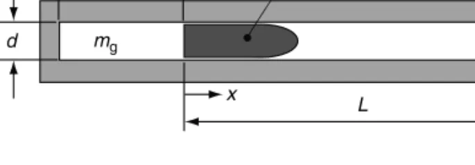
Let us imagine that we have a simple gun as depicted in Figure 2.1.
We shall assume that we have somehow placed a mass, mg, of a gas that behaves according to the ideal gas equation of state in the tube and compressed it, adiabatically, using the projectile and no leakage has occurred. We shall further assume that there is no friction between the projectile and the tube wall. Thus, in the situation depicted by Figure 2.1, we have an ideal gas trapped between the projectile and the breech, compressed to some pressure,p, at some absolute temperature, T. We shall further assume that the projectile of mass,mp, is somehow held at positionx¼0 and no gas or energy can escape.
In this situation, the volume the gas occupies, which we shall call the chamber volume, Vc, is given by
Vc¼pd2
4 l (2:14)
What we have done essentially is compressed the projectile against an imaginary spring (the gas), which now has a potential energy associated with it. From a thermodynamic standpoint, we can reduce Equation 2.6 to
0¼DUþW (2:15)
Recapping, we note that Q¼0 because there was no heat lost through the tube wall (adiabatic compression) and there is no propellant per se that will burn to generate heat.
The losses were zero because we have no friction.
Now that everything is set, we need to release our projectile and see what happens. If we substitute Equation 2.4 into Equation 2.13, we can write
W¼ ð
mgRTdV
V (2:16)
This equation now shows how much work is being done on the projectile as a function of the volume. It is noteworthy here that we are assuming the gas that is actually pushing on the projectile is massless. By this we mean that no energy is being applied to accelerate the mass of the gas. We will remove this assumption later in our studies. What we do not like about Equation 2.16 is that temperature still appears as a variable.
By our earlier assumptions, we stated that the process was frictionless and adiabatic.
Recall, again from thermodynamics, that this actually defines an isentropic process [1]. For a closed system (one with constant mass), it can be shown [6] that the absolute tempera- ture,T, of our system is related to the initial temperature of the gas,Ti, through
T¼Ti Vc
V
(g1)
(2:17)
FIGURE 2.1 Simple gun system.
l
d
x L mg
mp
In Equation 2.17, V is the volume at a given timet, Vcis the initial chamber volume, and g is the specific heat ratio of the gas (defined later). If we substitute Equation 2.17 into Equation 2.16, we can write
W¼mgRTiV(cg1) ðV
Vc
VgdV (2:18)
This equation is easy to work with because we know most of the terms on the RHS (right- hand side) when we set up our pedagogical gun. We know the mass,mg, of the gas. We knowRandgbecause we picked which gas it was. We know the initial temperature of the gas and we know the chamber volume.
Now that we did all of this work with volumes, we want to convert these back to distances. A typical output desired by ballisticians is the pressure versus travel (i.e., distance) curve. This plot helps the gun designer determine where to make his tube thick and where he can get away with thinning the wall. If we again recognize that our gun has a constant inner diameter, we can use Equation 2.14 to write Equation 2.18 as
W¼mgRTil(g1) ðL
0
(lþx)gdx (2:19)
If we perform this integration, we obtain
W¼mgRTil(g1)
(1g) (lþL)(1g)l(1g)
h i
(2:20)
We need to recall from dynamics that the kinetic energy of the projectile can be written as K:E:projectile¼1
2mpVm2 (2:21)
If we assume that all of the energy of the gas is converted with no losses into kinetic energy of the projectile, then we can use Equation 2.15 to state that
K:E:projectile¼W (2:22)
We can make use of Equations 2.20 and 2.21 to write this as 1
2mpV2m¼mgRTil(g1)
(1g) h(lþL)(1g)l(1g)i
(2:23) This is an important result as it relates muzzle velocity to the properties and amount of the gas used, the mass of the projectile, and includes the effect of tube length. We can use this equation to estimate muzzle velocity. So a convenient form of this equation is
Vm¼
ffiffiffiffiffiffiffiffiffiffiffiffiffiffiffiffiffiffiffiffiffiffiffiffiffiffiffiffiffiffiffiffiffiffiffiffiffiffiffiffiffiffiffiffiffiffiffiffiffiffiffiffiffiffiffiffiffiffiffiffiffiffiffiffiffiffiffiffiffiffiffi 2mg
mp
RTil(g1)
(1g) (lþL)(1g)l(1g)
h i
s
(2:24)
In some instances, we would like to use these relationships to determine the state of the gas or velocity of the projectile at some point in the tube other than the muzzle. If this is the case, the procedure would be as follows:
(1) Solve for the work term up to the position of interest,xproj, using
W(xproj)¼mgRTil(g1) ð
xproj
0
(lþx)gdx (2:25)
(2) Determine the volume at the position of interest using V(xproj)¼pd2
4 (lþxproj) (2:26)
(3) Determine the gas temperature at this position from Equation 2.17.
(4) Determine pressure from the ideal gas Equation 2.4.
This procedure is relatively straightforward.
If, as an example, we look at an idealized 155-mm compressed air gun and assume the following parameters
Projectile weight¼100 lbm
Initial pressure¼45 MPa (approximately 6500 psi) Tube length¼6 m
From Figures 2.2 through 2.4, we can depict the results of a calculation for temperature, pressure, and velocity versus distance for this idealized situation.
Temperature versus distance in ideal gas gun
0
0 1 2 3 4 5 6 7
50 100 150 200 250 300 350
Distance (m)
Temperature (K)
T(K)
FIGURE 2.2
Temperature versus distance in an ideal gas gun.
Problem 1
Assume we have a quantity of 10 g of 11.1% nitrated nitrocellulose (C6H8N2O9) and it is heated to a temperature of 1000 K assuming it changes from solid to gas somehow without changing chemical composition. If the process takes place in an expulsion cup with a volume of 10 in.3, assuming ideal gas behavior, what will thefinal pressure be in pounds per square inch?
Answer:p¼292 lbf in:2
Pressure versus distance in an ideal gas gun
0 5,000,000 10,000,000 15,000,000 20,000,000 25,000,000 30,000,000 35,000,000 40,000,000 45,000,000 50,000,000
Distance (m)
Pressure (Pa)
p (Pa)
0 1 2 3 4 5 6 7
FIGURE 2.3
Pressure versus distance in an ideal gas gun.
Velocity versus distance in an ideal gas gun
0 50 100 150 200 250
Distance (m)
Velocity (m/s)
V (m/s)
0 1 2 3 4 5 6 7
FIGURE 2.4
Velocity versus distance in an ideal gas gun.
2.2 Other Gas Laws
There are many times when ideal gas behavior is insufficient to model real gases. This is certainly true under the pressures and temperatures of gun launch. Although there are many models that attempt to account for the deviation of real gases from ideal or perfect behavior [2,3], we shall examine only two, the simplest of which we shall use.
Ideal gas behavior is approached when the distance between molecules (known as the mean free path) is large. Thus, molecules do not collide or interact with one another very often. Temperature is a measure of the internal energy of the gas. Thus, when the tem- perature is high, the molecules are moving around faster and have more of an opportunity to interact with one another. Pressure is a result of how closely the molecules are packed together, thus a higher pressure tends to put the molecules in close proximity. It is for these reasons that we cannot normally use the ideal gas law in gun launch applications.
The Noble–Abel equation of state is given by pVmgb
¼mgRT (2:27)
Here p is the pressure of the gas, V is the volume the gas occupies, mg is the mass of the gas,Ris the specific gas constant,Tis the absolute temperature, andbis the co-volume of the gas.
The co-volume of the gas has been described as a parameter which takes into account the physical size of the molecules and any intermolecular forces created by their proximity to one another. Think of it as not having physical meaning but as simply a number which allows for a betterfit to observed experimental data. The units of the co-volume are cubic length per mass unit. Usually, the gas co-volume is provided in the literature but an estimation tool has been provided by Corner [7] which will not be repeated here since actual data exists.
Occasionally, the Noble–Abel equation of state is insufficient to suit our needs. At these times, it is typical to use a Van der Waals equation of state given by
p¼ RT~
~
vb0a0
~
v2 (2:28)
In this case,pis again the pressure of the gas,~vis the molar specific volume,R~ is the molar specific gas constant, unique to each gas,Tis again the absolute temperature, anda0andb0 are constants particular to the gas.
The Noble–Abel equation of state is the basis for nearly all of our work in this text, therefore Equation 2.27 is very important. At times, we may write it a little differently but you will always be reminded of where it originated.
Problem 2
Perform the same calculation as in Problem 1, but use the Noble–Abel equation of state and assume the co-volume to be 32.0 in.3=lbm
Answer:p¼296:3 lbf in:2
2.3 Thermophysics and Thermochemistry
The main energy exchange process of conventional interior ballistics is through com- bustion. Once ignited, the chemical energy of the propellant is released through an
oxidation reaction. This energy release will be in the form of heat, which, in turn, increases the pressure in the volume behind the projectile (i.e., in a combustion chamber). The pressure exerts a force on the projectile, which accelerates it to the desired velocity.
In general, combustion requires three main ingredients to commence: a fuel, an oxygen source, and heat. In a common combustion reaction, such as an internal combustion engine like the one in your car, oxygen is supplied to the reaction independently of the fuel. The heat in this case is generated by a spark ignition and the burning of the air–fuel combination that ensues.
A gun chamber has very little room for oxygen once it is stuffed with propellant. It is important to note that, for other reasons, there is always free volume in the chamber (called ullage)—we will explain this later. For now, we should understand that although there is some oxygen in the chamber, the amount is insufficient to completely combust the pro- pellant. It is for this reason that propellants are formulated to contain both the fuel and the oxidizer. In general, the propellant burning is an under-oxidized reaction. This has some implications as the propellant gases leave the muzzle—again, we shall discuss this in more detail later.
This brief introduction should make clear the reason to examine thermochemistry, thermophysics, and combustion phenomena. To proceed, we shallfirst define eachfield of study. The definitions of Ref. [8] shall be used here to describe thefirst two topics as they are extremely straightforward and clear. Thermophysics is defined as the quantification of changes in a substance’s energy state caused by changes in the physical state of the material. An example of this would be the determination of the amount of energy required to vaporize water in your teapot. Thermochemistry is then the quantification of changes in a substance’s energy state caused by changes in the chemical composition of the material’s molecules. An example of this would be the energy required to dissociate (break up) water molecules into hydrogen and oxygen. Combustion is defined in Ref. [1] as the quantifica- tion of the energy associated with oxidizer–fuel reactions. Thus, combustion is a natural outgrowth of thermophysics and thermochemistry.
Now that we have categorized these three fields of study, we shall attack them in a somewhat jumbled order. The reason for this is that, from our perspective, we really need not distinguish between any of them and all of them appear in our gun launch physics. It is also important to realize that whether the energy change comes from a chemical reaction or a phase change from solid to gas, as long as we can calculate the extent of the energy change, we can perform a valuable analysis.
Energy to all intents and purposes consists of two types: potential and kinetic. Potential energy can be considered as stored energy. There are many ways to store energy. We can store energy by compressing a steel bar or spring, by lifting a mass to a higher elevation in the earth’s gravitationalfield, and by chemically preparing a compound that, whether by combustion or chemical reaction, will release energy. Each of these forms of potential energy elastic strain, gravitational potential and chemical potential energy, has a different method of storing and releasing the energy but they are all potential energies. There are other forms of potential energy but we need not deal with them in this context.
Kinetic energy is the energy of a mass in motion. It can be observed in objects that are in translational motion or in rotational motion. To extract some or all of this energy, it is necessary to slow or stop the moving mass that has the kinetic energy. The energy in a spinningflywheel is an example of rotational kinetic energy.
The field of thermodynamics is the study of energy transformations. It quantifies the balance of energy between kinetic and potential. In thermodynamics, it is common to see two energy transformation mechanisms: heat and work.
Heat transfer is essentially an exchange of energy through molecular motion. As we shall soon see, molecules of a substance are always in motion. The faster they are in motion, the
hotter the substance is. These molecules can influence other molecules when they are placed in contact with them, thus giving up some of their energy and increasing the energy of the contacted substance. Temperature is a sensible measure of an object’s internal energy.
Work is a means of increasing an object’s energy by application of a force through a distance. This method of energy transfer can create either potential energy, as in compress- ing a spring, or kinetic energy as applied to a free, rigid mass. While the equations for heat transfer can be the subject of entire texts (e.g., [9]), work can be defined through the vector equation
W¼Fdx (2:29)
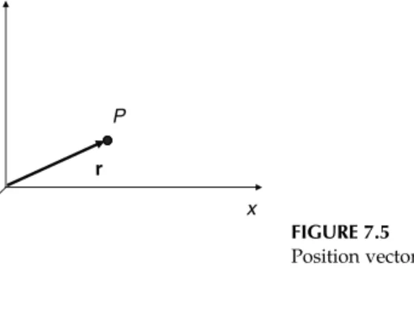
HereWis the work done on or by the system,Fis the force vector, and dx is the vector distance through which the force acts, known as the displacement vector. We must note that this is avector equation. The work term is a scalar because the dot product of two vectors results in a scalar. Because of the dot product term, the sign ofWis dependent upon the cosine of the angle betweenFand dx. Recall the definition of a dot product as
AB¼ABcosu (2:30)
Here A and Bare the scalar magnitudes of the vectors Aand B (Figure 2.5). If we use Equation 2.30 with the variables of Equation 2.29, this tells us that if the angle between the force vector and the displacement vector is between 08and 908or 2708and 08, the work is positive, i.e., it is work performed on the system. If, however the angle is between 908and 2708, the work is negative, and therefore work performed by the system.
Internal energy,U, of a substance can be considered a form of potential energy. Some authors [5] categorize the internal energy separately from potential and kinetic energies.
This can clearly be done in general, but for the application of gun launch it seems proper to group it as a potential energy. The internal energy of a substance is manifested in the molecular motions within that substance. These motions generally are translational or vibrational in nature. The molecules of a substance are attracted to and repelled by one another and are in some degree of translational motion. Additionally, the attractive or repulsive forces within a molecule itself allow us to use an analogy of springs holding the atoms together. Imagine a structure of a water molecule, for instance as depicted in Figure 2.6. If the oxygen and hydrogen atoms are assumed to be steel balls and the molecular bond springs, we could pick this molecule up, hold the oxygen atom, and shake it. If the springs were really stiff in bending and much less so in tension or compression, we would see the hydrogen atoms oscillating in and out at some frequency. The greater the fre- quency, the more energy we would need to put into the system. Even though the springs are stiff in bending, it does not mean that they cannot bend. This just takes more energy.
Like springs, we can store energy in the molecules this way.
FIGURE 2.5
Depiction of two vectors for scalar product definition.
A
B q
This simple model of a molecule is a crude but useful approximation. Imagine now that we put our model on a frictionless surface, like an ice hockey rink. If we hit the molecule in a random way, we will excite these vibrational modes as well as create translational and rotational motion. Now, if wefill the ice hockey rink with models . . . well, you get the idea.
As stated previously, the level of this interaction (collisions) must be represented some- how. The metric used is internal energy with the level of activity defined as zero at the temperature known as absolute zero (08on the Kelvin or Rankine scales).
The internal energy also includes the energy required to maintain a particular phase of the material such as solid, liquid, or gas. Additionally, certain phases associated with molecular structure such as face-centered cubic (FCC), body-centered cubic (BCC), etc.
are accounted for in the internal energy.
Quite often we shall see internal energy and what is commonly known as‘‘pdV’’work terms together in our energy balance equations. The term is calledpdV work because it is special and separate from work generated by, say, a paddle wheel movingfluid around.
This work term arises from pressure pushing on a given volume. If the volume changes by an infinitesimal amount, dV, we essentially have force acting through a distance. To prove this to yourself, look at the units. Because we see these terms together so often, it is convenient for us to group them into one term, which we will call enthalpy,H. Mathemati- cally, the enthalpy is defined as
H¼UþpV (2:31)
Notice here that we have removed the differential from the work term. The reason for this is that, considering both enthalpy and internal energy, we are concerned with changes in H and U. Therefore, the differential appears when we write the entire equation in differential form as
dH¼dUþpdV (2:32)
For proof of this result, refer to any thermodynamics text (e.g., [1,5]). An example of the difference between internal energy and enthalpy is the rigid container or piston container.
Consider a rigid container that has some amount of gas in it. Assume the container is sealed so that matter cannot enter or leave. Let us also assume that the container will allow energy to be transferred to and from the gas. If we transfer heat (energy) to the gas, the temperature will rise as will the pressure. Since the volume of the container isfixed, no work can be done; thus all of the energy added to the gas is internal energy. From Equation 2.32, we see that in this case the change in enthalpy would be exactly equal to the change of internal energy.
Now we assume that, instead of our container being rigid, the roof of the container is a sealed yet moveable piston. In this case, once again matter cannot escape, however, the volume is able to change. Now the only thing holding up the roof is the pressure of the gas acting to just counteract the weight of the roof itself. Let us add the same amount of heat
Hydrogen atoms Oxygen
atom
FIGURE 2.6
Model of a water molecule.
that we added to the original, rigid, container. In this case, the temperature of the gas will increase (but less than before) and the volume will increase because the piston is moveable and the pressure must remain constant and just sufficient to counteract the weight of the roof. In this instance, the enthalpy would be greater than the internal energy because it includes the work done in lifting the piston.
When a substance changes form, chemically or physically, energy is either absorbed or released. The method that we use to quantify this energy change is through heats of formation and the like. Though called a ‘‘heat,’’ what is really implied is an enthalpy change. We shall proceed through these different enthalpy changes, attempting to list some of the more common ones. For greater detail, the reader is encouraged to consult thermo- dynamics texts in addition to the descriptions provided in Ref. [8]. Specific values for text problems will be given as needed. It is not the intent of the authors to tabulate the different energy parameters of different materials.
When a substance is formed, atomic bonds in the constituent molecules are destroyed and then recreated (at least this is a clean way to think of it from a bookkeeping perspec- tive). The energy absorbed or generated by this process is commonly called the heat of reaction,DHr0. TheDreminds us that we always are concerned with changes in enthalpy from a particular reference state (usually standardized as 258C and 1 atm). The ‘‘0’’
superscript is a convenient reminder that this is from a reference state of 1 atm. As the subscript, sometimes we see‘‘298’’meaning 298 K. Though 298 K and 258C are the same value, one must always be wary of the reference state chosen by a particular author.
The heat of formation,DHf0, is the energy required to form a particular substance from its individual component atoms. The heats of formation are the building blocks that deter- mine the heat of reaction. Any elemental substance in its stable configuration at standard conditions has a heat of formation equal to zero at that state. For instance, diatomic nitrogen, N2, has DHf0¼0 at 258C and 1 atm. We will provide an example of the heat of formation calculation in a later section.
Now that with the above quantities defined, we can write an equation for the heat of reaction
DH0r ¼ X
products
DH0f X
reactants
DH0f (2:33)
Equation 2.33 states that the heat of reaction for a given substance is equal to the sum of the heats of formation of the final products of the reaction that created the substance minus the sum of the heats of formation of the materials that had to be reacted together to create the new substance. This is further reinforcement of the definition of the heat of reaction. Recall that we stated the atomic bonds of the molecules were destroyed and then remade. This is essentially what Equation 2.33 is saying. The energy it took to create each of the reactants has to be accounted for and then the energy it takes to create the new substances from the constituents is calculated—energy is conserved. If the heat of reaction is a negative number, heat is liberated by the reaction otherwise it is absorbed.
When a compound is specifically combusted with sufficient oxygen to attain its most oxidized state, the heat of reaction has a special name the heat of combustion. The heat of combustion is identified by the symbol DHc0. The heat of combustion is typically what is obtained when propellant is burned in a closed bomb. The equation for the heat of combustion mirrors that of the heat of reaction, the only difference being as noted above.
DHc0¼ X
fully oxidized products
DH0f X
reactants
DHf0 (2:34)
The heats of detonation and explosion have meanings which seem to be reversed. The heat of detonation is the heat of reaction taken when detonation products are formed from an explosive compound during a detonation event. The formula for the heat of detonation is given by
DH0d¼ X
detonation products
DH0f X
original explosive
DHf0 (2:35)
What is termed the heat of explosion is the amount of energy released when a propellant or explosive is burned (not detonated) and is given by
DH0exp¼ X
burning products
DH0f X
original propellants
DH0f (2:36)
The heat of afterburn is another type of heat of reaction that occurs often in propellants and explosives. Because the composition of propellants and explosives usually force an under-oxidized reaction, the reaction products will often combine with the oxygen present in the air outside the gun or explosive device, given sufficient temperature and pressure.
This secondary reaction results in a second pressure wave or blast and afireball. The heat of afterburn can be described mathematically as
DHAB0 ¼ X
fully oxidized products
DHc0 X
remaining detonation products
DH0d (2:37)
Not all energy changes involve chemical reactions. We mentioned earlier that changes in physical state and structure require energy. When a solid melts to form a liquid or a liquid solidifies, we call the energy required, the latent heat of fusion, lf. These values are tabulated in any chemistry book or thermodynamics text. Some authors use different symbols so one must, as always, be careful.
In a similar vein, the energy required to vaporize a liquid to a gas or condense a gas to a liquid is known as the latent heat of vaporization and given by the symbollfg.
If a material changes the structure of its atoms, say from BCC to FCC, the energy is known as the heat of transition,lt.
There are many other types of material transitions that require energy. The types described above cover the needs of this work.
2.4 Thermodynamics
The combustion process that occurs in a gun is a thermodynamic process. The term thermodynamics is a bit misleading because it implies that the dynamics of the combustion process is examined. This is not quite true. Classical thermodynamics is based on the examination of the various processes through equilibrium states. This is somewhat akin to frames of a motion picture. We examine the state of the system before some event and we usually examine it at some point, later in time, we are interested in.
Some of the concepts of thermodynamics were introduced in earlier sections, work and energy being the major ones. Here we shall look in detail at two ways of describing thermodynamic systems to proceed with our study.
We shall define energy for an arbitrary system as E¼Uþ1
2mV2þmgz (2:38)
Equation 2.38 is our extensive form of the definition of the system energy, E. In this equation, U is the internal energy, m is the system mass, Vis the system velocity, g is a gravitational constant, and z is some height above a reference datum. The second and third terms on the RHS of the equation are the kinetic and potential energies, respectively. If we examine this equation, it is easy to see why some authors group the internal energy as a separate energy type. However, in the case of a gun launch, the potential energy term is insignificant. This focuses us on the transfer of energy between internal and kinetic.
We sometimes write Equation 2.38 in its intensive form as e¼uþ1
2V2þgz (2:39)
Recall from our earlier discussions that an intensive property is the associated extensive property divided by mass.
We shall now examine thefirst law of thermodynamics as it is applied to two different types of systems: a fixed mass of material and a fixed volume of space through which materialflows. Thefirst type of analysis, where the material is afixed mass, is known as a Lagrangian approach, while the fixed or control volume (CV) approach is known as Eulerian. Both are important from a ballistic analysis standpoint and are prevalent in interior, exterior, and terminal ballistic studies.
For afixed mass of material, undergoing some thermodynamic process, thefirst law of thermodynamics can be written as
Q12þW12¼DE12 (2:40)
In this equation,Qis the heat or energy added to the system,Wis the work performed on or by the system, andDEis the change in the energy state of the material. The subscript 1–2 simply lets us know that the process began at some state 1 and ends at some state 2. The signs on the terms are very important. We assume a positive change in energy comes about through adding heat to the system and doing work on the system. Thus, work performed on the system is positive and heat added is also positive. Different thermodynamics texts write thefirst law slightly different, but if you understand that the net result of work on the system or heat transfer to the system is to increase its energy, then few mistakes will be made.
An interesting observation of Equation 2.40 is that the energy state change has an infinite number of paths that lead to the same result. For instance, if we wanted to add 24 kJ of energy to some arbitrary system, we could do it by adding 12 kJ of heat and performing 12 kJ of work on the system. We could obtain the same result by adding 36 kJ of heat and extracting 12 kJ of work from the system. The possibilities are limitless. This reinforces our assertion that thermodynamics is really only concerned with end states.
Caution is warranted at this point. Equation 2.40 does not say how the energy, once added to the system, is partitioned between potential (internal) energy or kinetic energy.
This reveals something. Heat and work are added to or removed from the system at the system boundaries while the distribution of energy between internal or kinetic energy is done within the system.
We shall now write out Equation 2.40 explicitly for a Lagrangian system Q1---2þW1---2¼m u2þ1
2V22
u1þ1 2V21
(2:41)
Here we have neglected the gravitational potential energy terms and used the intensive form of the energy, multiplied by the system mass. As previously stated, many times we would like to use enthalpies instead of internal energies. If this is the case, we can rewrite Equation 2.41 using our relationship between the two from Equation 2.40. We shall use the intensive form of Equation 2.40 to yield
Q1---2þW1---2¼m h2pv2þ1 2V22
h1pv1þ1 2V21
(2:42)
Here we note thathis the specific enthalpy andvis the specific volume.
We shall now examine the first law of thermodynamics in the Eulerian frame of reference. Recall that in the Eulerian frame, we chose a CV (real or imaginary) and observed how the energy within the volume changes based upon the energy carried into or out of it by any entering or exiting substance as well as any heat or work done at the system boundaries. It is convenient for us to write thefirst law in terms of the time rate of change of energy, heat, and work. We start by writing Equation 2.40 as a rate equation
dQ dt þdW
dt ¼dE
dt (2:43)
or
Q_ þW_ ¼E_ (2:44)
Here the dots over the heat and work terms indicate the time rate of change of the variable.
Proper thermodynamics terminology would require us to use the‘‘d’’ instead of ‘‘d’’ in Equation 2.43 because of path dependency considerations, but for our purposes we shall ignore this fact. The reader is advised to consult any thermodynamics text for a better understanding of the difference.
The substitutions that were performed to arrive at Equation 2.41 are not as straight- forward in this case. Because we have material entering and leaving the CV, we can imagine that this material can enter or leave with a different pressure and density as it interacts with ourfixed CV. Because of this, we must account for the energy used to make these changes. Alternatively, one can envision the material coming in at a higher pressure or density and wanting to push our imaginary CV outward, but since wefixed our CV it cannot. The energy from this must go somewhere so it works on thefluid in and around our CV. Mathematically, this results in the energy term in Equation 2.44 having to include apvterm. This is sometimes known asflow work [10]. With this in mind, Equation 2.44 can be written as
Q_ þW_ ¼m_outðeoutþpoutvoutÞ m_inðeinþpinvinÞ (2:45) Here by multiplying the intensive properties by the massflow rate,m, we have the rate of_ change of the energy terms. We have also arbitrarily assumed one inlet and one outlet.
If more inlets or outlets in our CV were present and they had different massflow rates