This study was supported by contract DOD-4996 between the National Academy of Sciences and the Department of Defense. The National Academy of Engineering was established in 1964, under the charter of the National Academy of Sciences, as a parallel organization of outstanding engineers.
Contents
5 BARRIERS TO VIRTUAL DESIGN AND PRODUCTION IN DOD ACQUISITION 74 Need for requirements definition and management, 74.
Executive Summary
- Systems Engineering: The Department of Defense should develop tools to facilitate the definition of high-level mission
- Engineering Design: The Department of Defense should develop interoperable and composable tools that span multiple technical
- Manufacturing: The Department of Defense should
- Life-Cycle Assessment: The Department of Defense should develop tools and databases that enable life-cycle costs and
- Engineering Education: The Department of Defense should invest in the education and training of future generations of engineers
- Defense Acquisition Processes: The Department of Defense should define best practices for government ownership rights to
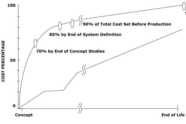
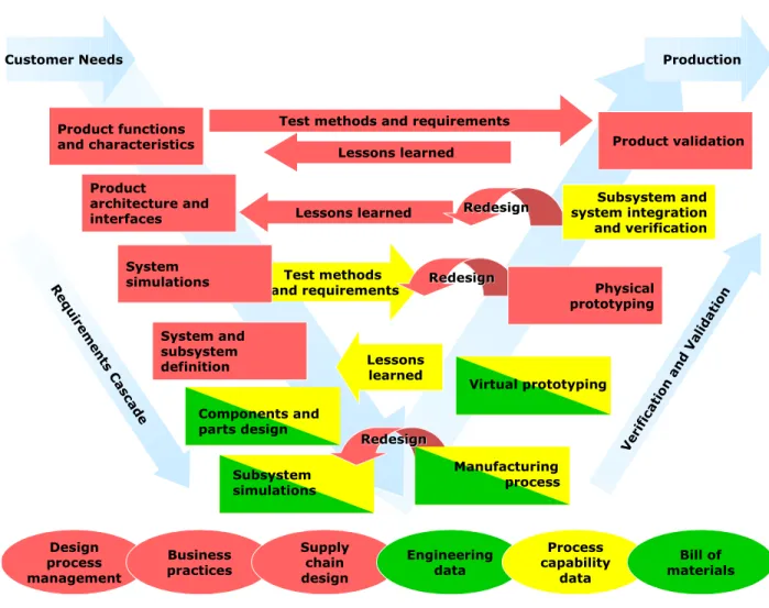
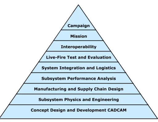
Design and manufacture construction requires the ability to conceptualize, analyze, and make decisions at all levels of V in Figure ES-1. As depicted by the color scheme in Figure ES-1, software tools are not available (red) for many of the required products.
The Need to Bridge Design, Materials, and Production
Furthermore, efficient production, including adapting and responding quickly to customer orders, requires increasing integration between design and production. At the technical level, there is a fundamental need for a deeper understanding of the complex interactions between design decisions and manufacturing options.
Framework for Virtual Design and Manufacturing
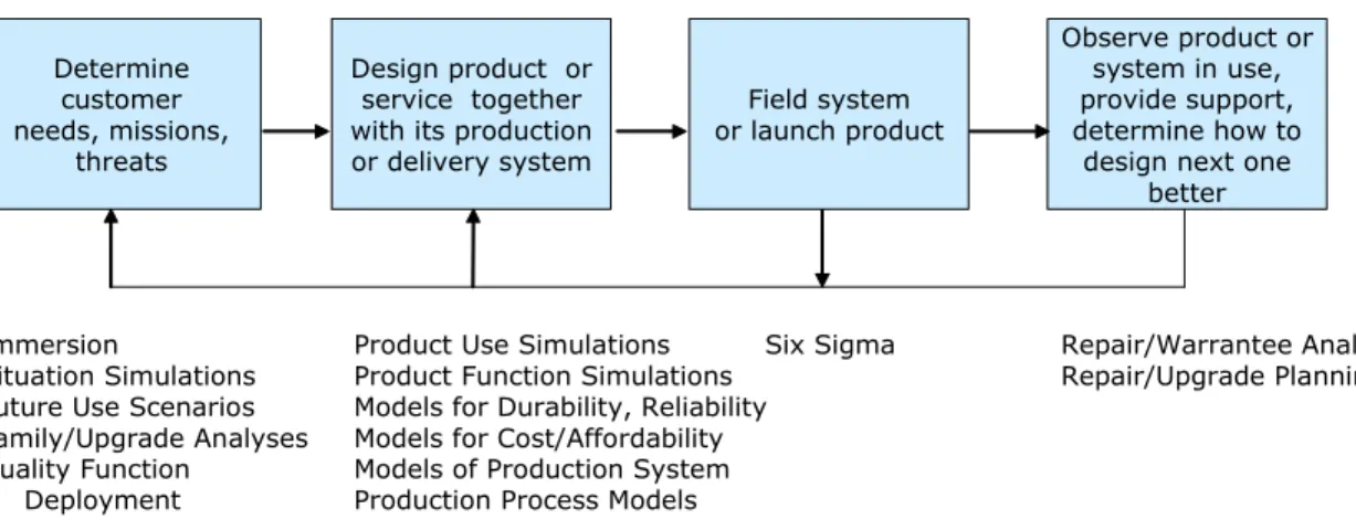
Other tools help predict failure modes of the product in use as well as problems that may occur during. Additionally, they can be used to guide the design process into those areas of the design space where sensitivity is low.
Tools for Virtual Design and Manufacturing
ADAMS, Calibre, DADS, DOORS, Dynasty, EASA, Engineous, Innovation Management, LMS, MatLab, MSC, Opnet, Phoenix, RDD-OM, RDD-SD, Statemate, VL. Abaqus, AML, ANSoft, Ansys, Calibre, DICTRA, DOORS, DYNA3D, EASA, EDS, Engineous, Functional Prototyping, ICEM CFD, LMS, ModelCenter, MSC, NASTRAN, Phoenix, RDD-SD, Statemate, Stella/Ithink.
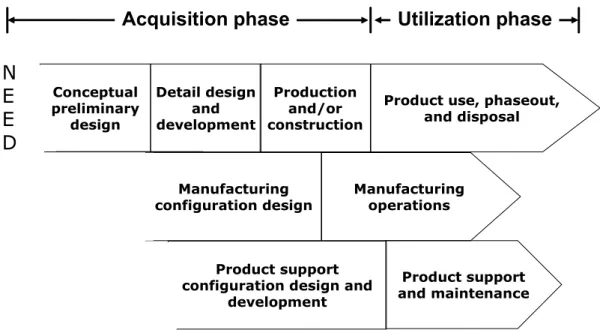
Acquisition phase Utilization phase
Box 3-1 shows four case studies of the use of systems engineering software tools in industry. In the initial design review, the customer found no discrepancy reports, and the results of the final design review reflected the first. This manufacturing engineering process includes many of the same steps as in the engineering design process, including the application of advanced modeling and simulation.
The columns represent many of the identifiable stages in the design of a new product or system, with time running from left to right. The development of the UUV offers several lessons for bridging the gap between design and manufacturing. Equally important in the selection process is the processing technique and manufacturability of the components.
The two most important components of any engine are the cylinder head and the block. Also, much, if not most, of the value of cars and aircraft is outsourced, requiring the coordination of planning and production across many organizational boundaries. The inventory provides a more or less quantitative overview of the material and energy flows that occur during the product's life cycle.
A significant number of subjective judgments enter this phase of the assessment, often buried in the details of the data compilation. Life cycle assessment information is included in the definition of the process activities and the estimation of the IO coefficients.

Economic Dimension of Bridging Design and Manufacturing
Developing virtual computer simulation of the manufacturing process from design concept to product life and disposal will enable a company to rapidly examine multiple designs and the trade-offs between various objectives, including performance, cost and environmental impact. While the external supplier may deliver at a lower cost, the company or public authority loses the ability to retain any strategic benefits of integration, such as greater knowledge of the design process and how it can be developed into new systems. As illustrated in the case of integrated design for the unmanned underwater vehicle (UUV), (see Box 3-2), the development costs of the ARL design tools were funded under a defense contract with the U.S.
Bridge design and fabrication requires the integration of various engineering tools developed for various key elements of the overall process as shown in Figure 3-1. The aerospace and automotive industries invest heavily in design tools, both commercial and homegrown, because of the increased speed and accuracy of the resulting designs, the ability to design manufacturing systems faster, and the high cost of an error. Technologies that bridge design and manufacturing will undoubtedly require highly trained engineers who possess knowledge of several different areas.
This erosion of the manufacturing base can have a negative impact on innovation and on national. Bridging the gap between design and manufacturing can be too complex and expensive for any lone firm to achieve. What is the utility function of the design process in terms of trade-offs between cost, fatigue life, flexibility and other properties.
Barriers to Virtual Design and Manufacturing in DoD Acquisition
Hollenbach, Simulation Strategies, Inc., "Modeling and Simulation in Aerospace," presented to the Committee on Bridging Design and Manufacturing, National Research Council, Washington, D.C., February 24, 2003. The rapidly developing field of virtual modeling and simulation has the potential to to significantly improve the DoD acquisition process. The use of modeling and simulation to guide the establishment of realistic requirements, which all relevant.
Garrett, "Opportunities in Modeling and Simulation to Enable Dramatic Improvements in Ordnance Design," presented to the Committee on Ordnance Design and Production, National Research Council, Washington, D.C., April 29, 2003; and M. Lilienthal, "Observations on the Use of Modeling and Simulation," presented to the Committee on Bridge Design and Manufacturing, National Research Council, Washington, DC, February 24, 2003. Traditional barriers between levels and lack of data transfer between levels remain one of the major obstacles for stronger use of modeling and simulation to positively impact DoD acquisition.
This is an important barrier to more effective use of modeling and simulation in all steps of the acquisition process (see Figure 5.1). Nevertheless, integrating modeling and simulation tools to enable bridges from one acquisition phase to the next remains one of SBA's major challenges. Lilienthal, "Observations on the Uses of Modeling and Simulation," presented to the Committee on Bridging Design and Manufacturing, National Research Council, Washington, D.C., February 24, 2003.
Summary, Recommendations, and Research Needs
Tools to create, visualize and analyze design and manufacturing alternatives can facilitate system-level decision making. It is critical that this issue be addressed in order to pave the way for design and manufacturing to become a reality. A new generation of engineers trained to accept, and indeed expect, integration of design and manufacturing is the best long-term solution.
Life Cycle Assessment: The Ministry of Defense should develop tools and databases that enable life cycle costing, and should develop tools and databases that enable life cycle cost and environmental impact to be quantified and integrated into design and manufacturing processes. Effective bridging of design and manufacturing will require better ability to seamlessly pass design data between the different levels. Improved design and analysis methods are critical to successfully bridging the gap between design and manufacturing.
As outsourcing becomes more common, and with it some degree of offshoring, maintaining design and manufacturing capacity in the United States is a real concern. Incentives for program managers to develop integrated design and production tools could make simulation-based acquisition a reality for DoD programs. Well-defined metrics for the integration of design and production can help program managers use simulation-based acquisition.
Appendixes
Appendix A
Biographical Sketches of Committee Members
Antonsson is currently on the editorial board of the international journals Research in Engineering Design and Fuzzy Sets and Systems, and from 1989 to 1993 served as an associate technical editor of the ASME Journal of Mechanical Design (formerly the Journal of Mechanisms, Transmissions and Automation in Design), with responsibility for the design research and the design theory and methodology areas. Babin is the director of the Virtual Design and Manufacturing Group at Motorola Advanced Technology Center. Boardman is past chair and a current member of the ASM International Database Committee and the Federal Affairs Committee.
Mark Gersh is currently manager of the Lockheed Martin Advanced Technology Center's Modeling, Simulation and Information Sciences Department responsible for the pursuit of destabilizing information technologies critical to the success of the Lockheed Martin Space Systems Company. He also serves as the Lockheed Martin program manager for an effort with the Advanced Systems and Technology arm of the National Reconnaissance Office that investigates constructions for agile design and development of space systems. He is a fellow of ASM International and serves on the International Scientific Advisory Board of the European DYMAT Association.
Holm is a distinguished member of the technical staff, Materials and Process Modeling at Sandia National Laboratories. Koshiba is the deputy director of Boeing's Phantom Works Lean and Efficient Thrust. Koshiba is a member of Sigma Gamma Tau - the National Honor Society for Aerospace Engineers - and a senior fellow of the American Institute of Aeronautics and Astronautics.
Appendix B
Meeting Agendas
-Yuan Liou, Ford Motor Company Virtual Manufacturing—Rough parts form Alan Lecz, Ford Motor Company. Discussion of best practices, identification of gaps and what is needed to bridge the design. to manufacturing gap).
Appendix C
Current Engineering Design Tools
EMP (electromagnetic pulse) / lightning strike analysis tools are used to determine the survivability of a product to these phenomena—whether natural or human-induced. Environmental analysis tools are used to describe the environments to which a product is subjected, including temperature, pressure, humidity, and others. TPS (thermal protection system) analysis tools are used to design and analyze the performance of the systems used to protect or insulate a product from the thermal environments to which it is exposed.
Durability analysis tools are used to predict the economic life of a structure based on expected use, material, and stress concentration. Environmental control design and analysis tools are used to define on-board environmental control systems and simulate their operation. Fluid flow design and analysis tools are used to design and analyze platform fluid systems.
Fuel design and analysis tools are used to define onboard fuel systems and simulate their performance. Hydraulic systems design and analysis tools are used to define on-board hydraulic systems and simulate their performance. Wiring schematic design and analysis tools are used to generate design and analyze the performance of schematic diagrams.
Selected Computer-Based Tools Vendors
Appendix E Acronyms
JSF Joint Strike Fighter LCA life cycle assessment LCI life cycle inventory LFT&E live-fire test and evaluation LRIP low rate initial production.