Other documents that provide suggestions for carrying out the requirements of the Code are also cited. Design reference materials that illustrate the applications of the Code requirements can be found in the following documents.
ACI 318, “Building Code Requirements for Struc- tural Concrete,” is hereafter referred to as “this Code.”
In case of conflict between the official version of this Code and other versions of this Code, the official version
If no general building code is adopted, this Code provides minimum requirements for the materials, design,
Construction means and methods are not addressed in this Code
This Code shall apply to concrete structures designed and constructed under the requirements of the general
The design of thin shells and folded plate concrete structures shall be in accordance with ACI 318.2, “Building
Concrete used in the construction of such slabs shall be governed by this Code, where applicable.
The principles of interpretation in this section shall apply to this Code as a whole unless otherwise stated
The Commentary is intended to provide contextual information, but is not part of this Code, does not provide binding requirements, and may not be used to create a conflict with or ambiguity in this Code. Specific definitions of words and terms in this Code will be used where available and applicable, regardless of whether other materials, standards or sources outside this Code provide a different definition.
The following words and terms in this Code shall be interpreted in accordance with (a) through (e)
If conflicts occur between provisions of this Code and those of standards and documents referenced in Chapter
The building official shall have the right to order testing of any materials used in concrete construction to
Concrete materials shall be tested in accordance with the requirements of Chapter 26
Concrete construction shall be inspected in accor- dance with the general building code and in accordance with
Inspection records shall include information required in Chapters 17 and 26
These rules, when approved by the building official and promulgated, shall have the same force and effect as the provisions of this code. For special systems addressed under this section, specific tests, load factors, deflection limits, and other relevant requirements should be determined by the Board of Examiners and should be consistent with the intent of the code.
This chapter defines notation and terminology used in this Code
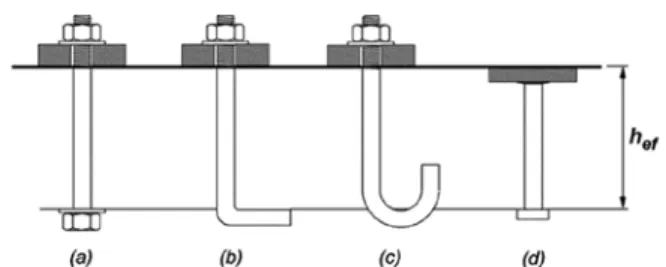
Cm = factor relating the actual moment diagram to an equivalent uniform moment diagram. d = distance from extreme compression fiber to center of gravity of longitudinal timber reinforcement, mm. d′ = distance from extreme compression fiber to center of gravity of longitudinal compression reinforcement, mm da = outside diameter of anchor or shaft diameter of. head bolt, head bolt or hook bolt, mm da′ = value replaced by da if an anchor is too large. dagg = nominal maximum size of coarse aggregate, mm db = nominal diameter of bar, wire or prestressing. dp = distance from extreme compression fiber to center of gravity for tension reinforcement, mm. dpile = diameter of pile at footing, mm D = effect of dead load. eh = distance from the inner surface of the shaft of a J or L bolt to the outer tip of the J or L bolt, mm e′N = distance between resultant tensile load on a group. of anchors loaded in tension and the center of gravity of the group of anchors loaded in tension, mm; eN′ is always positive. e′V = the distance between the resulting shear load on a group of anchors loaded in shear in the same direction and the center of gravity of the group of anchors loaded in shear in the same direction, mm; eV′ is always positive E = effect of horizontal and vertical earthquake induced. Deflection is measured relative to the position of the structure at the beginning of the second load test, etc.
Terms such as building commissioner or building inspector are variations of the title, and the term "building official" as used in this Code is intended to include those variations as well as others used in the same sense. For the proper application of the provisions of the Code, the limits of substitution must be declared, with interpolation if partial substitution of sand is used.
American Welding Society (AWS)
This chapter shall apply to design of structural concrete in structures or portions of structures defined in
- Diaphragms, such as floor or roof slabs, shall be designed to resist simultaneously both out-of-plane gravity
- Diaphragms and their connections to framing members shall be designed to transfer forces between the
- Diaphragms and their connections shall be designed to provide lateral support to vertical, horizontal,
- Diaphragms shall be designed to resist applicable lateral loads from soil and hydrostatic pressure and other
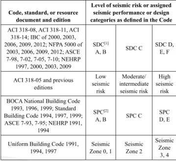
Structures classified in Seismic Design Category A need not be designed in accordance with Chapter 18. For structures classified in Seismic Design Categories D, E, and F, the diaphragm design shall be in accordance with Chapter 18.
The methods of analysis given in Chapter 6 shall be permitted
Design strength of a member and its joints and connections, in terms of moment, axial force, shear, torsion,
Structures and structural members shall have design strength at all sections, ϕS n , greater than or equal to the
Evaluation of performance at service load condi- tions shall consider reactions, moments, torsions, shears,
Concrete mixtures shall be designed in accordance with the requirements of 19.3.2 and 26.4, considering appli-
Reinforcement shall be protected from corrosion in accordance with 20.6
The licensed design professional shall be permitted to specify in the construction documents sustainability
The strength, serviceability, and durability require- ments of this Code shall take precedence over sustainability
Structural concrete members shall satisfy the fire protection requirements of the general building code
Where the general building code requires a thick- ness of concrete cover for fire protection greater than the
- Design of precast concrete members and connec- tions shall include loading and restraint conditions from
- Design, fabrication, and construction of precast members and their connections shall include the effects of
- When precast members are incorporated into a structural system, the forces and deformations occurring in
- Where system behavior requires in-plane loads to be transferred between the members of a precast floor or
- Distribution of forces that act perpendicular to the plane of precast members shall be established by anal-
- Design of prestressed members and systems shall be based on strength and on behavior at service conditions
- Provisions shall be made for effects on adjoining construction of elastic and plastic deformations, deflec-
- Stress concentrations due to prestressing shall be considered in design
- Effect of loss of area due to open ducts shall be considered in computing section properties before grout in
- Post-tensioning tendons shall be permitted to be external to any concrete section of a member. Strength
- This Code shall apply to composite concrete flex- ural members as defined in Chapter 2
- Individual members shall be designed for all crit- ical stages of loading
- Members shall be designed to support all loads introduced prior to full development of design strength of
- Reinforcement shall be detailed to minimize cracking and to prevent separation of individual components
- Composite compression members shall include all members reinforced longitudinally with structural steel
- The design of composite compression members shall be in accordance with Chapter 10
The strength and serviceability design requirements of this Code shall be used to evaluate the effects of external tendon forces on the concrete structure. R4.12.2 Prestressed concrete systems—Prestressing, as used in the Code, may apply to prestressing, bonded posttensioning, or unbonded posttensioning.
Structural plain concrete systems
- The design of structural plain concrete members, both cast-in-place and precast, shall be in accordance with
Specifications for construction execution shall be in accordance with Chapter 26
Inspection during construction shall be in accor- dance with Chapter 26 and the general building code
Live load reductions shall be permitted in accor- dance with the general building code or, in the absence of a
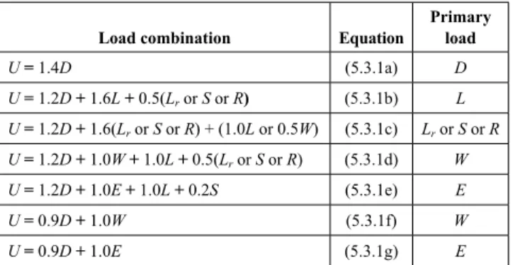
If F acts alone or contributes to the effects of D, it must be included with a load factor of 1.4 in the equation. b). If the effect of H is permanent and counteracts the primary load effect, it must be factored in with a load factor of 0.9.
This chapter shall apply to methods of analysis, modeling of members and structural systems, and calcula-
Members and structural systems shall be permitted to be modeled in accordance with 6.3
All members and structural systems shall be analyzed for the maximum effects of loads including the arrangements
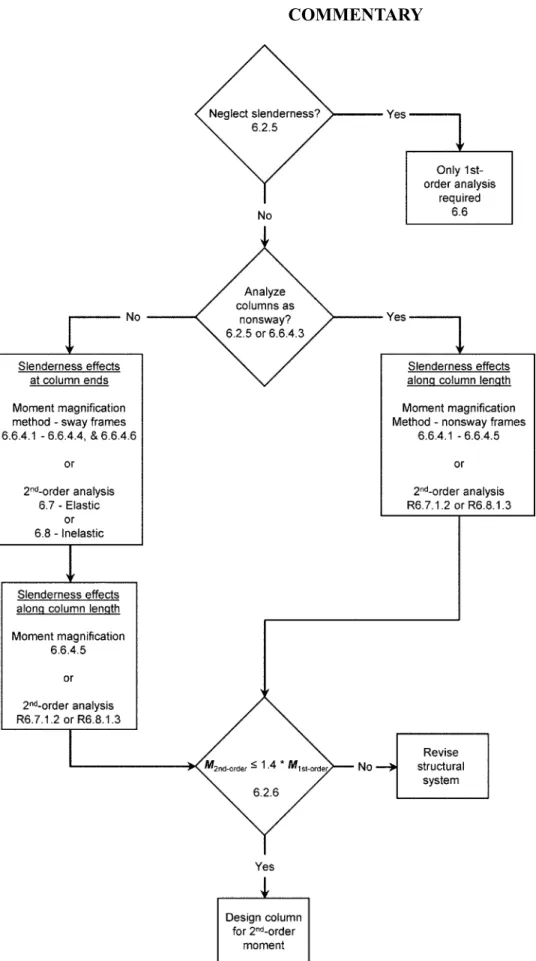
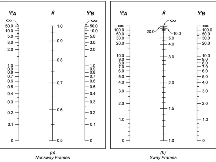
Slenderness effects can be neglected in both strengthened and unreinforced systems, depending on the slenderness ratio (kℓh/r) of the element. The stiffness of the lateral reinforcement is assessed based on the main directions of the frame system.
Additional analysis methods that are permitted include .1 through .4
- Two-way slabs shall be permitted to be analyzed for gravity loads in accordance with (a) or (b)
- Slender walls shall be permitted to be analyzed in accordance with 11.8 for out-of-plane effects
- Diaphragms shall be permitted to be analyzed in accordance with 12.4.2
- A member or region shall be permitted to be analyzed and designed using the strut-and-tie method in
- The radius of gyration, r, shall be permitted to be calculated by (a), (b), or (c)
- To calculate moments and shears caused by gravity loads in columns, beams, and slabs, it shall be permitted
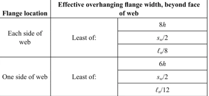
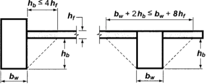
- Isolated nonprestressed T-beams in which the flange is used to provide additional compression area shall
Torsional response of the lateral force-resisting system due to the eccentricity of the structural system may increase second-order effects and should be considered. The code now allows one-eighth of the span on each side of the joist.
For the design of floors or roofs to resist gravity loads, it shall be permitted to assume that live load is applied
- If the arrangement of L is known, the slab system shall be analyzed for that arrangement
- If L is variable and does not exceed 0.75D, or the nature of L is such that all panels will be loaded simultane-
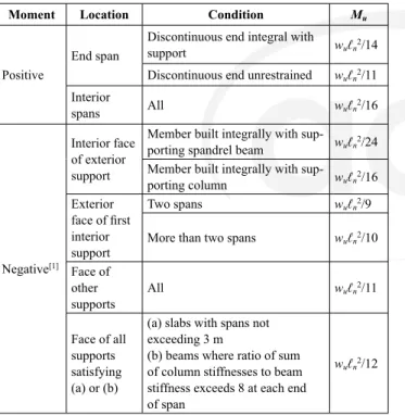
Bar built integrally with load-bearing parapet beam wuℓn2/24 Bar integrally built with load-bearing column wuℓn2/16 Exterior. Face of all supports complying with (a) or (b). a) slabs with a span not exceeding 3 m. b) beams where the ratio of the sum of the column stiffness to the beam stiffness is greater than 8 at each end of the span.
Moments calculated in accordance with 6.5.2 shall not be redistributed
- Redistribution of moments calculated by an elastic first-order analysis shall be permitted in accordance with 6.6.5
- For frames or continuous construction, consid- eration shall be given to the effect of floor and roof load
- The cross-sectional dimensions of each member used in an analysis shall be within 10 percent of the specified
- Except where approximate values for moments are used in accordance with 6.5, where moments have been
- At the section where the moment is reduced, redis- tribution shall not exceed the lesser of 1000 ε t percent and
- The reduced moment shall be used to calculate redistributed moments at all other sections within the spans
- Shears and support reactions shall be calculated in accordance with static equilibrium considering the redistrib-
- The cross-sectional dimensions of each member used in an analysis to calculate slenderness effects shall be
- Redistribution of moments calculated by an elastic second-order analysis shall be permitted in accordance with
- Factored load analysis
- An inelastic second-order analysis shall consider material nonlinearity, member curvature and lateral drift,
- The cross-sectional dimensions of each member used in an analysis to calculate slenderness effects shall be
- Redistribution of moments calculated by an inelastic second-order analysis shall not be permitted
6.6.4.6.3 Flexural members shall be designed for the total magnified end moments of the columns at the joint. R6.7.1.1 The stiffnesses EI used in an analysis for strength design shall represent the stiffnesses of the members immediately before failure.
The licensed design professional shall confirm that the results are appropriate for the purposes of the analysis
For example, to determine the ultimate element inelastic response, it is not correct to analyze for service loads and then combine the results linearly using load factors.
The cross-sectional dimensions of each member used in an analysis shall be within 10 percent of the speci-
Redistribution of moments calculated by an inelastic analysis shall not be permitted
Materials
- Design properties for concrete shall be selected to be in accordance with Chapter 19
- Design properties for steel reinforcement shall be selected to be in accordance with Chapter 20
- Materials, design, and detailing requirements for embedments in concrete shall be in accordance with 20.7
Connection to other members
- For cast-in-place construction, beam-column and slab-column joints shall satisfy Chapter 15
- For precast construction, connections shall satisfy the force transfer requirements of 16.2
- For solid nonprestressed slabs not supporting or attached to partitions or other construction likely to be
- The thickness of a concrete floor finish shall be permitted to be included in h if it is placed monolithically
- For nonprestressed slabs not satisfying 7.3.1 and for prestressed slabs, immediate and time-dependent deflec-
- For nonprestressed composite concrete slabs satis- fying 7.3.1, deflections occurring after the member becomes
A1 - 7.3.1.1.3 For non-prestressed composite slabs made of a combination of lightweight and normal concrete, encased during construction and where the lightweight concrete is in compression, the modifier of 7.3.1.1.2 shall apply. Deflections that occur before the member becomes composite shall be investigated, unless the thickness of the precomposite also satisfies 7.3.1.
Reinforcement strain limit in nonprestressed slabs .1 For nonprestressed slabs, ε t shall be at least 0.004
R7.3.2 Calculated deflection limits—The basis for calculating deflections for unidirectional slabs is the same as that for beams.
Stress limits in prestressed slabs
- Prestressed slabs shall be classified as Class U, T, or C in accordance with 24.5.2
- Required strength shall be calculated in accor- dance with the factored load combinations in Chapter 5
- Required strength shall be calculated in accor- dance with the analysis procedures in Chapter 6
- For prestressed slabs, effects of reactions induced by prestressing shall be considered in accordance with
R7.4.3.2 The requirements for selecting the critical section for shear in one-way slabs are the same as for beams.
Factored moment
- ϕ shall be determined in accordance with 21.2
- For prestressed slabs, external tendons shall be considered as unbonded tendons in calculating flexural
R7.5.2.3 This provision only applies if the T-beam is parallel to the span of the unidirectional plate. In this case, the primary slab reinforcement is parallel to the beam and the perpendicular reinforcement is usually dimensioned for temperature and shrinkage.
Shear
- For composite concrete slabs, horizontal shear strength V nh shall be calculated in accordance with 16.4
- For slabs with both flexural and shear design strength at least twice the required strength, 7.6.2.1 need not
- Concrete cover for reinforcement shall be in accor- dance with 20.6.1
- Development lengths of deformed and prestressed reinforcement shall be in accordance with 25.4
- Bundled bars shall be in accordance with 25.6
- Minimum spacing s shall be in accordance with 25.2
- For nonprestressed and Class C prestressed slabs, spacing of bonded longitudinal reinforcement closest to the
- Maximum spacing s of deformed reinforcement shall be the lesser of 3h and 450 mm
- Critical locations for development of reinforce- ment are points of maximum stress and points along the span
- Continuing flexural tension reinforcement shall have an embedment length at least ℓ d beyond the point
- Flexural tension reinforcement shall not be termi- nated in a tension zone unless (a), (b), or (c) is satisfied
- Adequate anchorage shall be provided for tension reinforcement where reinforcement stress is not directly
- In slabs with spans not exceeding 3 m, welded wire reinforcement, with wire size not exceeding MW30 or
- External tendons shall be attached to the member in a manner that maintains the specified eccentricity between
- If nonprestressed reinforcement is required to satisfy flexural strength, the detailing requirements of 7.7.3
- Termination of prestressed reinforcement
- If shear reinforcement is required, transverse rein- forcement shall be detailed according to 9.7.6.2
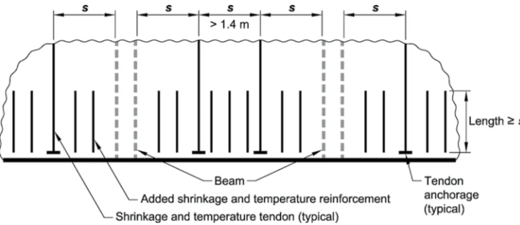
- Shrinkage and temperature reinforcement in accor- dance with 7.6.4 shall be placed perpendicular to flexural
- Nonprestressed reinforcement
7.7.6.3.2 If the spacing of placing tendons exceeds 1.4 m, additional deformed shrinkage and temperature reinforcement must be provided in accordance with 24.4.3 parallel to the tendons, except that 24.4.3.4 need not be complied with. When calculating the area of additional reinforcement, it will be allowed to take the gross concrete area in Table 24.4.3.2 as the slab area between the levels of beams.
This chapter shall apply to the design of nonpre- stressed and prestressed slabs reinforced for flexure in
If the dimensions are less than specified in 8.2.4, the projection may be used as a shear cap to increase the shear strength of the plate. R8.3.1 Minimum slab thickness—The minimum slab thicknesses in 8.3.1.1 and 8.3.1.2 are independent of the load and modulus of elasticity of the concrete, both of which have significant effects on deflections.
Slabs prestressed with an average effective compres- sive stress less than 0.9 MPa shall be designed as nonpre-
R8.2.4 and R8.2.5 The drop panel dimensions specified in 8.2.4 are required when reducing the amount of negative moment reinforcement per 8.5.2.2 or to meet the minimum plate thicknesses permitted in 8.3.1.1. R8.2.7 Connections to Other Members—The safety of a slab system requires consideration of load transmission from slabs to columns by bending, torsion, and shear.
Materials
- Design properties for concrete shall be selected to be in accordance with Chapter 19
- Design properties for steel reinforcement shall be selected to be in accordance with Chapter 20
- Materials, design, and detailing requirements for embedments in concrete shall be in accordance with 20.7
- Beam-column and slab-column joints shall satisfy Chapter 15
- If single- or multiple-leg stirrups are used as shear reinforcement, the slab thickness shall be sufficient to satisfy
2]For fy between the values given in the table, the minimum thickness is calculated by linear interpolation. 1]αfm is the average value of αf for all beams at the edges of the slab and αf is calculated in accordance with 8.10.2.7.
![Table 8.3.1.1—Minimum thickness of nonpre- nonpre-stressed two-way slabs without interior beams (mm) [1]](https://thumb-ap.123doks.com/thumbv2/123dok/11178695.0/97.918.105.668.410.687/table-minimum-thickness-nonpre-nonpre-stressed-slabs-interior.webp)
Stress limits in prestressed slabs
- Required strength shall be calculated in accor- dance with the factored load combinations in Chapter 5
- For prestressed slabs, effects of reactions induced by prestressing shall be considered in accordance with
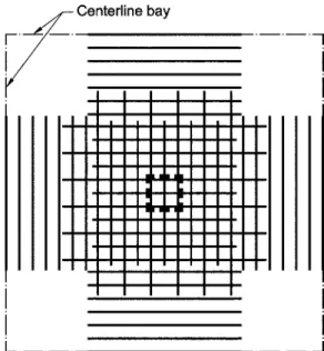
- For a slab system supported by columns or walls, dimensions c 1 , c 2 , and ℓ n shall be based on an effective
- A column strip is a design strip with a width on each side of a column centerline equal to the lesser of 0.25ℓ 2
- A middle strip is a design strip bounded by two column strips
- Combining the results of a gravity load analysis with the results of a lateral load analysis shall be permitted
- For slabs analyzed using the direct design method or the equivalent frame method, M u at the support shall be
Deflections that occur before the member is assembled shall be examined unless the precomposite thickness also satisfies 8.3.1.1 or 8.3.1.2. 8.4.2.3.6 The portion of Msc not intended to resist bending shall be assumed to be resisted by shear eccentricity in accordance with 8.4.4.2.
Factored one-way shear
- Sections between the face of support and a critical section located d from the face of support for nonprestressed
- Critical section
- ϕ shall be in accordance with 21.2
For rectangular columns, the portion of the moment transferred by bending increases as the width of the face of the critical section resisting the moment increases, as given by Eq. The portion of Msc not transferred by eccentricity of displacement shall be transferred by bending in accordance with 8.4.2.3.
Moment
- For composite concrete slabs, horizontal shear strength V nh shall be calculated in accordance with 16.4
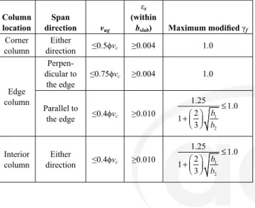
Interaction between load effects will be considered. a) ϕMn ≥ Mu at all sections along the span in each direction (b) ϕMn ≥ γfMsc within bslab as defined in c) ϕVn ≥ Vu at all sections along the span in each direction for unidirectional shear. 8.5.3.1.1 For unidirectional shear, where each critical section to be examined extends in a plane over the entire plate width, Vn must be calculated in accordance with 22.5.
Openings in slab systems
- Openings of any size shall be permitted in slab systems if shown by analysis that all strength and service-
- As an alternative to 8.5.4.1, openings shall be permitted in slab systems without beams in accordance with
- Concrete cover for reinforcement shall be in accor- dance with 20.6.1
- Development lengths of deformed and prestressed reinforcement shall be in accordance with 25.4
- Splice lengths of deformed reinforcement shall be in accordance with 25.5
- Bundled bars shall be detailed in accordance with 25.6
- Minimum spacing s shall be in accordance with 25.2
- External tendons shall be attached to the slab in a manner that maintains the specified eccentricity between the
- Termination of prestressed reinforcement
- Stirrup anchorage and geometry shall be in accor- dance with 25.7.1
- If stirrups are provided, location and spacing shall be in accordance with Table
- Headed shear stud reinforcement shall be permitted if placed perpendicular to the plane of the slab
- Nonprestressed two-way joist construction consists of a monolithic combination of regularly spaced ribs and a
- Width of ribs shall be at least 100 mm at any loca- tion along the depth
- Overall depth of ribs shall not exceed 3.5 times the minimum width
- For structural integrity, at least one bottom bar in each joist shall be continuous and shall be anchored to
- Reinforcement area perpendicular to the ribs shall satisfy slab moment strength requirements, considering
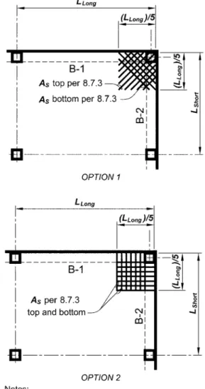
Concentration of this reinforcement in the top of the slab immediately above and immediately adjacent to the column is important. 8.7.3.1.3 Reinforcement shall be placed parallel to the diagonal in the top of the slab and perpendicular to the diagonal in the bottom of the slab.
Joist systems with structural fillers
- If permanent burned clay or concrete tile fillers of material having a unit compressive strength at least equal to
Joist systems with other fillers
- If fillers not complying with 8.8.2.1 or removable forms are used, slab thickness shall be at least the greater of
In slabs constructed with lift-slab methods where it is impractical to pass the tendons required by 8.7.5.6.1 or
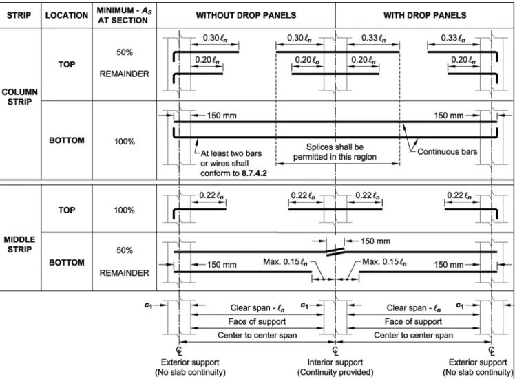
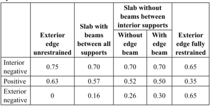
- The column strip shall resist the portion of inte- rior negative M u in accordance with Table
- If the width of the column or wall is at least (3/4)ℓ 2 , negative M u shall be uniformly distributed across ℓ 2
- The column strip shall resist the portion of posi- tive M u in accordance with Table
- For slabs with beams between supports, the slab portion of column strips shall resist column strip moments
- That portion of negative and positive factored moments not resisted by column strips shall be proportion-
- Each middle strip shall resist the sum of the moments assigned to its two half middle strips
- A middle strip adjacent and parallel to a wall- supported edge shall resist twice the moment assigned to the
- Columns and walls built integrally with a slab system shall resist moments caused by factored loads on the
- Beams between supports shall resist the portion of shear in accordance with Table caused by factored
- In addition to shears calculated according to 8.10.8.1, beams shall resist shears caused by factored loads
- Calculation of required slab shear strength based on the assumption that load is distributed to supporting
R8.10.4.2 The moment coefficients for the end span are based on equivalent column stiffness expressions from Corley et al. R8.10.4.6 Moments perpendicular to and at the edge of the slab structure shall be transferred to supporting columns or walls.
General
- All sections of slabs and supporting members in two-way slab systems designed by the equivalent frame
- Live load shall be arranged in accordance with 6.4.3
- It shall be permitted to account for the contri- bution of metal column capitals to stiffness, resistance to
- It shall be permitted to neglect the change in length of columns and slabs due to direct stress, and deflec-
- The structure shall be modeled by equivalent frames on column lines taken longitudinally and transversely
- Each equivalent frame shall consist of a row of columns or supports and slab-beam strips bounded later-
- Frames adjacent and parallel to an edge shall be bounded by that edge and the centerline of the adjacent
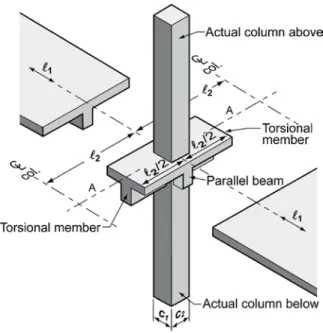
- Columns or supports shall be assumed to be attached to slab-beam strips by torsional members trans-
- If slab-beams are analyzed separately, it shall be permitted to calculate the moment at a given support
- Variation in moment of inertia along the axis of slab-beams shall be taken into account
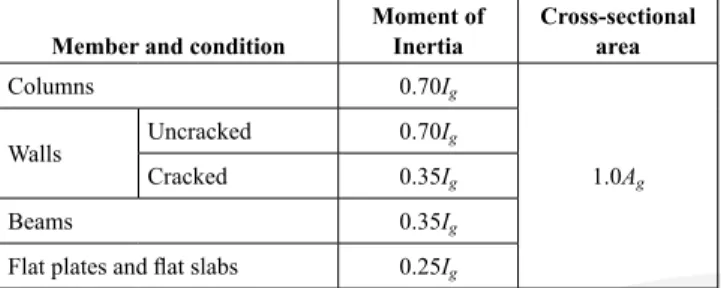
- It shall be permitted to use the gross cross- sectional area of concrete to determine the moment of
- The moment of inertia of columns from top to bottom of the slab-beam at a joint shall be assumed to be
- Variation in moment of inertia along the axis of columns shall be taken into account
- It shall be permitted to use the gross cross- sectional area of concrete to determine the moment of inertia
- Torsional members shall be assumed to have a constant cross section throughout their length consisting of
- Where beams frame into columns in the direc- tion of the span for which moments are being calculated,
- It shall be permitted to distribute moments at crit- ical sections to column strips, beams, and middle strips in
- Design properties for concrete shall be selected to be in accordance with Chapter 19
- Design properties for steel reinforcement shall be selected to be in accordance with Chapter 20
- Materials, design, and detailing requirements for embedments in concrete shall be in accordance with 20.7
R8.11.5 Torsional members - Calculation of the stiffness of a torsional member requires several simplifying assumptions. R8.11.5—Unit moment distribution along the centerline of column AA shown in the beam or cap figure beyond the face of the support member.
Connection to other members
- For cast-in-place construction, beam-column and slab-column joints shall satisfy Chapter 15
- For precast construction, connections shall satisfy the force transfer requirements of 16.2
- Effective flange width shall be in accordance with 6.3.2
The overhanging flanges should be neglected in cases where the parameter Acp2/pcp for solid profiles or Ag2/pcp. Deflections that occur before the element becomes composite must be investigated unless the depth of the pre-composite also complies with 9.3.1.
Stress limits in prestressed beams
- Prestressed beams shall be classified as Class U, T, or C in accordance with 24.5.2
- Required strength shall be calculated in accor- dance with the analysis procedures in Chapter 6
- For prestressed beams, effects of reactions induced by prestressing shall be considered in accordance with 5.3.11
R9.4.3.2a shall extend upwards from the face of the support and reach the compression zone approximately d from the face of the support. Typical support conditions where the shear force can be used at a distance d from the support include:.
Factored moment
- Unless determined by a more detailed analysis, it shall be permitted to take the torsional loading from a slab as
- ϕ shall be determined in accordance with 21.2
The loads applied to the beam between the surface of the support and the point d away from the surface are transferred directly to the support by compression in the path above the crack. In that case, the critical cut must be taken at the face of the support.
Shear
- For beams with both flexural and shear design strength at least twice the required strength, 9.6.2.1 need not
- A minimum area of torsional reinforcement shall be provided in all regions where T u ≥ ϕT th in accordance
- Concrete cover for reinforcement shall be in accor- dance with 20.6.1
- Development lengths of deformed and prestressed reinforcement shall be in accordance with 25.4
- Bundled bars shall be in accordance with 25.6
- For nonprestressed and Class C prestressed beams, spacing of bonded longitudinal reinforcement closest to the
- Adequate anchorage shall be provided for tension reinforcement where reinforcement stress is not directly
- Termination of prestressed reinforcement
- General
- Shear
- Width of ribs shall be at least 100 mm at any loca- tion along the depth
- Overall depth of ribs shall not exceed 3.5 times the minimum width
- Reinforcement perpendicular to the ribs shall be provided in the slab as required for flexure, considering
The seventh edition of the PCI Design Handbook (PCI MNL-120) describes the procedure of Zia and Hsu (2004). R9.7.5.1 Longitudinal reinforcement is required to resist the sum of longitudinal tensile forces due to buckling.
Joist systems with structural fillers
- If permanent burned clay or concrete tile fillers of material having a unit compressive strength at least equal to
A limit on the maximum spacing between ribs is required because of the provisions that allow higher shear strengths and less concrete cover for the reinforcement of these relatively small, repetitive elements. This increase in shear strength is justified based on: 1) satisfactory performance of a girder structure designed with higher rated shear strengths specified in previous codes that allowed for comparable shear stresses;
Joist systems with other fillers
- If fillers not complying with 9.8.2.1 or removable forms are used, slab thickness shall be at least the greater of
- Strut-and-tie models in accordance with Chapter 23 are deemed to satisfy 9.9.1.2
- Concrete cover shall be in accordance with 20.6.1
- Spacing of distributed reinforcement required in 9.9.3.1 shall not exceed the lesser of d/5 and 300 mm
- At interior supports, (a) and (b) shall be satisfied
R9.9.4.5 The use of the strut-and-tie method for the design of deep beams illustrates that tensile forces in the bottom reinforcement must be anchored to the face of the support. From this consideration, the strengthening of the connection should be continuous or developed at the front end of the support (Rogowsky and MacGregor 1986).
Design of plain concrete pedestals shall be in accor- dance with Chapter 14
- Design properties for concrete shall be selected to be in accordance with Chapter 19
- Materials, design, and detailing requirements for embedments in concrete shall be in accordance with 20.7
Connection to other members
- For cast-in-place construction, beam-column and slab-column joints shall satisfy Chapter 15
- For columns with a square, octagonal, or other shaped cross section, it shall be permitted to base gross area
- For columns built monolithically with a concrete wall, the outer limits of the effective cross section of the
- ϕ shall be determined in accordance with 21.2
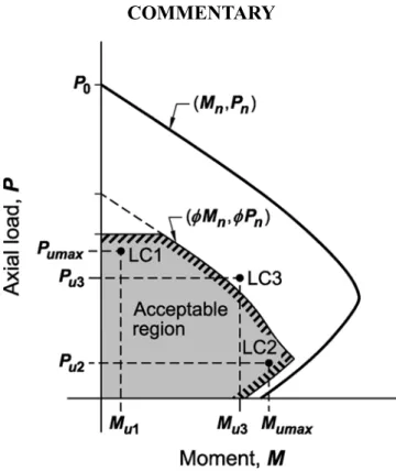
R10.4.2.1 Critical load combinations can be difficult to discern without methodically checking each combination. R10.6.1.2 Longitudinal and transverse reinforcement is required to prevent spalling and to ensure that the concrete outside the structural steel core behaves as reinforced concrete.
Shear
R10.5.4 Torsion—Torsion acting on columns in buildings is generally negligible and is rarely a determining factor in column design. R10.6.1 Minimum and maximum longitudinal reinforcement R10.6.1.1 Limits are given for both minimum and maximum longitudinal reinforcement ratios.
Minimum and maximum longitudinal reinforcement .1 For nonprestressed columns and for prestressed
- Bundled bars shall be in accordance with 25.6
Maximum Reinforcement—The amount of longitudinal reinforcement is limited to ensure that concrete can be effectively consolidated around the bars and to ensure that columns designed to the Code are similar to the test specimens against which the Code is calibrated. R10.7.3.1 At least four longitudinal bars are required when bars are surrounded by rectangular or circular bands.
Reinforcement spacing
- Minimum spacing s shall be in accordance with 25.2
For other tie shapes, one bar should be provided at each top or corner and proper transverse reinforcement should be provided. For example, tied triangular columns require at least three longitudinal bars, with one at each apex of the triangular ties.
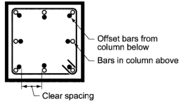
Offset bent longitudinal reinforcement
- Lateral support of offset bent longitudinal bars .1 Where longitudinal bars are offset, horizontal
- Shear
10.7.5.2.1 If the member force due to calculated loads is compressive, compression lap joints are permitted. The transverse reinforcement shall be distributed within 125mm of the top of the column or pedestal and shall consist of at least two no.
Design of walls as grade beams shall be in accor- dance with 13.3.5
- Design properties for concrete shall be selected to be in accordance with Chapter 19
- Design properties for steel reinforcement shall be selected to be in accordance with Chapter 20
- Materials, design, and detailing requirements for embedments in concrete shall be in accordance with 20.7
This chapter applies to the design of non-prestressed and prestressed walls, including (a) to (c):. a) On-site assembly (b) Factory assembly.
Connection to other members
- For precast walls, connections shall be designed in accordance with 16.2
- Connections of walls to foundations shall satisfy 16.3
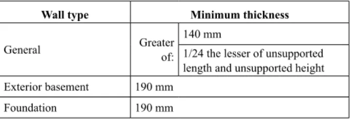
R11.2.4.1 Walls that do not rely on intersecting elements for support are not required to be connected to those elements. R11.3.1.1 The minimum thickness requirements need not be applied to exterior load-bearing walls and exterior basement and foundation walls designed in accordance with 11.5.2 or analyzed in accordance with 11.8.
Load distribution
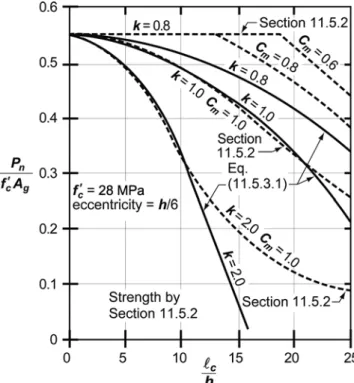
R11.5.2 Axial loading and in- or out-of-plane bending 11.4.1.4 Walls shall be designed for eccentric axial loads.
Factored axial force and moment
Factored shear
- Walls shall be designed for the maximum in-plane V u and out-of-plane V u
- ϕ shall be determined in accordance with 21.2
- Wall reinforcement shall be at least that required by 11.6
Eccentric axial loads and moments due to out-of-plane forces are used to determine the maximum total factored axial force eccentricity Pu. The equation results in strengths comparable to those determined in accordance with 11.5.2 for members loaded in the middle third of the thickness with various clamped and constrained end conditions.
In-plane shear
Expression (d) corresponds to the occurrence of web shear cracking at a principal tensile stress of approximately 0.33λ fc′ at the center of the shear wall cross-section. Expression (e) corresponds approximately to the occurrence of flexural-shear cracks at a flexural tensile stress of 0.5λ fc′ at a section ℓw/2 above the section under investigation.
Out-of-plane shear
- Development lengths of deformed and prestressed reinforcement shall be in accordance with 25.4
- Splice lengths of deformed reinforcement shall be in accordance with 25.5
Spacing of longitudinal reinforcement
One layer consisting of at least half and not more than two-thirds of the total required reinforcement for each direction shall be placed at least 50 mm, but not more than h/3, from the outer surface. The other layer, consisting of the balance of the required reinforcement in that direction, shall be placed at least 20 mm, but not exceeding h/3, from the inner surface.
Spacing of transverse reinforcement
- Spacing s of transverse bars in precast walls shall not exceed the lesser of (a) and (b)
For walls with h more than 250 mm, except for basement walls and cantilever retaining walls, the distributed reinforcement for each direction is laid in two layers parallel to the faces of the walls in accordance with (a) and (b):. a).
Lateral support of longitudinal reinforcement .1 If longitudinal reinforcement is required for axial
Reinforcement around openings
- The wall shall be analyzed as a simply supported, axially loaded member subject to an out-of-plane uniformly
- Concentrated gravity loads applied to the wall above any section shall be assumed to be distributed over a
Such bars must be anchored to develop tension at the corners of the openings. It is permitted to analyze out-of-plane slenderness effects in accordance with this section for walls satisfying (a) through (e):. a) The cross-section is constant along the height of the wall (b).
- Design properties for concrete shall be selected to be in accordance with Chapter 19
- Design properties for steel reinforcement shall be selected to be in accordance with Chapter 20
- Diaphragms shall have thickness as required for stability, strength, and stiffness under factored load
- Floor and roof diaphragms shall have a thick- ness not less than that required for floor and roof elements in
- Required strength of diaphragms, collectors, and their connections shall be calculated in accordance with the
- ϕ shall be determined in accordance with 21.2
- For a diaphragm that is entirely cast-in-place, cross-sectional dimensions shall be selected to satisfy Eq
Manifolds in such structures must be provided to transfer diaphragm shear to the vertical members of the lateral force resisting system. R12.5.4.2 Tensile and compressive forces in a collector are determined by the membrane shear forces they transfer to the vertical members of the lateral force-resisting system (see Fig. R12.5.4.1).
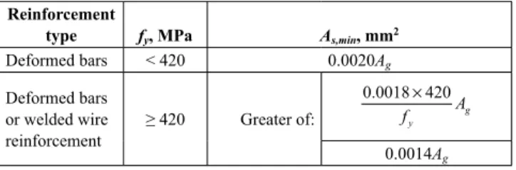
Reinforcement to resist shrinkage and temperature stresses shall be in accordance with 24.4
R12.7.1.1 For a structure assigned to seismic design category D, E, or F, the concrete cover may be governed by the seismic design requirements of 18.12.7.6. R12.7.2.1 For construction assigned to seismic design category D, E, or F, the spacing of confining reinforcement in manifolds may be governed by the seismic design requirements of 18.12.7.5.
Except for slabs-on-ground, diaphragms that are part of floor or roof construction shall satisfy reinforcement
Reinforcement designed to resist diaphragm in-plane forces shall be in addition to reinforcement designed
- Development lengths of deformed and prestressed reinforcement shall be in accordance with 25.4, unless longer
- Splices of deformed reinforcement shall be in accordance with 25.5
- Bundled bars shall be in accordance with 25.6
- Maximum spacing s of deformed reinforcement shall be the lesser of five times the diaphragm thickness and
- Except for slabs-on-ground, diaphragms that are part of floor or roof construction shall satisfy reinforce-
R12.7.3.2 Critical sections for reinforcement development are generally at points of maximum stress, at points where adjacent completed reinforcement is no longer required to resist design forces, and at other points of discontinuity in the membrane. To simplify design and avoid excessively long bar extensions that could occur if the beam devices were applied to diaphragms, this provision only requires that the tension reinforcement extend ℓd beyond points where it is no longer necessary to resist tension.
Foundations excluded by 1.4.6 are excluded from this chapter
- Design properties for concrete shall be selected to be in accordance with Chapter 19
- Design properties for steel reinforcement shall be selected to be in accordance with Chapter 20
- Materials, design, and detailing requirements for embedments in concrete shall be in accordance with 20.7
R13.2.3.1 The base of a structure, as determined in the analysis, does not necessarily correspond to the foundation or ground level, or to the base of a building as defined in the general building code for planning (for example, for height limits or fire protection requirements). Details of columns and walls extending below the base of a structure to the foundation are required to be consistent with those above the base of the structure.
Connection to other members
- Design and detailing of cast-in-place and precast column, pedestal, and wall connections to foundations shall
- Slabs-on-ground that transmit vertical loads or lateral forces from other parts of the structure to the ground
- Slabs-on-ground that transmit lateral forces as part of the seismic-force-resisting system shall be designed
R13.2.4 Floor slabs - Floor slabs often act as a diaphragm to hold the building together at ground level and reduce the effects of out-of-phase ground motion that may occur above the building plan. As required by Chapter 26, the construction documents must clearly state that these slabs on the floor are structural elements to prohibit the cutting of such slabs.
Plain concrete
- Plain concrete foundations shall be designed in accordance with Chapter 14
- External moment on any section of a strip footing, isolated footing, or pile cap shall be calculated by passing
- Circular or regular polygon-shaped concrete columns or pedestals shall be permitted to be treated as square
R13.2.6.3 An example of the application of this provision is a pile cap supported on piles, similar to that shown in Fig. The critical shear section is measured from the face of the supported element (column, pedestal or wall). , except for masonry walls and elements supported on steel base plates.
Development of reinforcement in shallow founda- tions and pile caps
- Development of reinforcement shall be in accor- dance with Chapter 25
- Calculated tensile or compressive force in rein- forcement at each section shall be developed on each side
- Critical sections for development of reinforcement shall be assumed at the same locations as given in 13.2.7.1
- Adequate anchorage shall be provided for tension reinforcement where reinforcement stress is not directly
- Overall depth of foundation shall be selected such that the effective depth of bottom reinforcement is at least 150 mm
For shear calculation, the ground reaction shall be obtained from calculated loads and the design strength shall be in accordance with Chapter 22. Supported member Location of critical section Column or pedestal Front of column or pedestal Column with steel base plate Midway between face of column and .
One-way shallow foundations
- The design and detailing of one-way shallow foundations, including strip footings, combined footings,
- Reinforcement shall be distributed uniformly across entire width of one-way footings
- The design and detailing of two-way isolated footings shall be in accordance with this section and the
- In square two-way footings, reinforcement shall be distributed uniformly across entire width of footing in
- The direct design method of 8.10 shall not be used to design combined footings and mat foundations
In sloped, stepped or tapered foundations, the depth and location of the steps or the angle of inclination shall be such that the design requirements are met at each section. For reinforcement in the short direction, a portion of the total reinforcement, γsAs, must be uniformly distributed over a band width equal to the length of the short side of the footing, centered on the center line of the column or pedestal.
Walls as grade beams
- The design of walls as grade beams shall be in accordance with the applicable provisions of Chapter 9
- If a grade beam wall is considered a deep beam in accordance with 9.9.1.1, design shall satisfy the require-
- Grade beam walls shall satisfy the minimum rein- forcement requirements of 11.6
- Overall depth of pile cap shall be selected such that the effective depth of bottom reinforcement is at least
- Factored moments and shears shall be permitted to be calculated with the reaction from any pile assumed to
- Except for pile caps designed in accordance with 13.2.6.3, the pile cap shall be designed such that (a) is satis-
For intermediate pile center positions, the part of the pile reaction considered to cause section shear shall be based on a linear interpolation between the full value at dpile/2 outside the section and the zero value at dpile/2 inside the section.
Deep foundation members
- Portions of deep foundation members in air, water, or soils not capable of providing adequate restraint
This chapter shall apply to the design of plain concrete members, including (a) and (b)
K14.2.2.2 Provisions for ordinary concrete walls apply only to walls laterally supported in such a way that relative lateral displacement at the top and bottom of individual wall elements is prevented. R14.2.3 Precast – Precast structural members of plain concrete are considered subject to all limitations and provisions for cast-in-place concrete contained in this chapter.
Materials
- Steel reinforcement, if required, shall be selected to be in accordance with Chapter 20
- Materials, design, and detailing requirements for embedments in concrete shall be in accordance with 20.7
- Tension shall not be transmitted through outside edges, construction joints, contraction joints, or isolation
- Precast members shall be connected to transfer lateral forces into a structural system capable of resisting
- Base area of footing shall be determined from unfactored forces and moments transmitted by footing to
- The number and location of contraction or isola- tion joints shall be determined considering (a) through (f)
R14.3.1 Load-bearing walls—Plain concrete walls are commonly used for the construction of basement walls for residential and light commercial buildings in low or non-seismic areas. R14.3.3.1 The height-thickness limitation for plain concrete bases does not apply to portions of bases embedded in the ground that can provide lateral support.
Walls
- Walls shall be designed for an eccentricity corre- sponding to the maximum moment that can accompany
When the design strength is exceeded, the cross-section must be increased or the prescribed strength of the concrete must be increased, or both, or the member must be designed as a reinforced concrete member in accordance with the Code. Increasing the concrete section can have a detrimental effect; the stress due to loading will decrease, but the stresses due to creep, shrinkage and temperature effects may increase.
Footings .1 General
- Factored moment