All the challenges we faced together produced these pages, I simply did the typing. Each point of the snowflake will be different from the others, but will follow the same basic pattern.
Determinism
Instead, this book is about how to organize your approach so that you can begin to create innovative machines that can react to ever-changing conditions to perform useful tasks. In the process of doing this, we begin to see our own human behavior in a new light.
Rule-based systems, state-driven systems, and other potential tar pits
The second most frustrating phase of a complex project is determining the architecture to use. The first, most frustrating stage is realizing after months of trying to implement a flawed architecture that it has degenerated into a mass of blobs and tools, that it has lost all elegance and that it will have to be razed to the ground and rebuilt. .
Robot
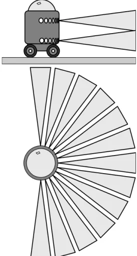
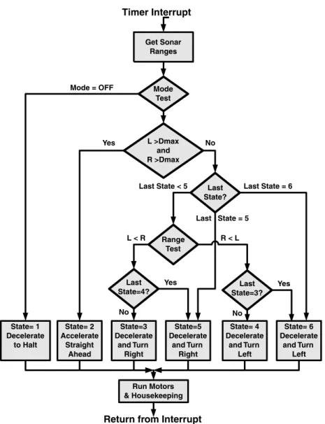
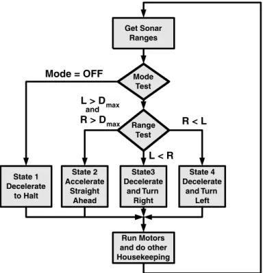
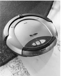
As an example of how quickly a purely state-driven system can become unmanageable, let's look at a very primitive robot. To make the problem even simpler, we'll forget about the navigation and assume we just want it to keep moving.
L R D max D stop
State functions 3 and 4 will calculate the rotation speed of the robot and its acceleration or deceleration. If this happens, we can force the robot to keep moving away from the nearest obstacle until State 2 is reached.
Defining an open architecture
In the course of this book, I hope to demystify many of these concepts, and to help you understand the essence of their meaning. Not only are most of these concepts relatively simple at their core, but many of the concepts are reflected across multiple disciplines.
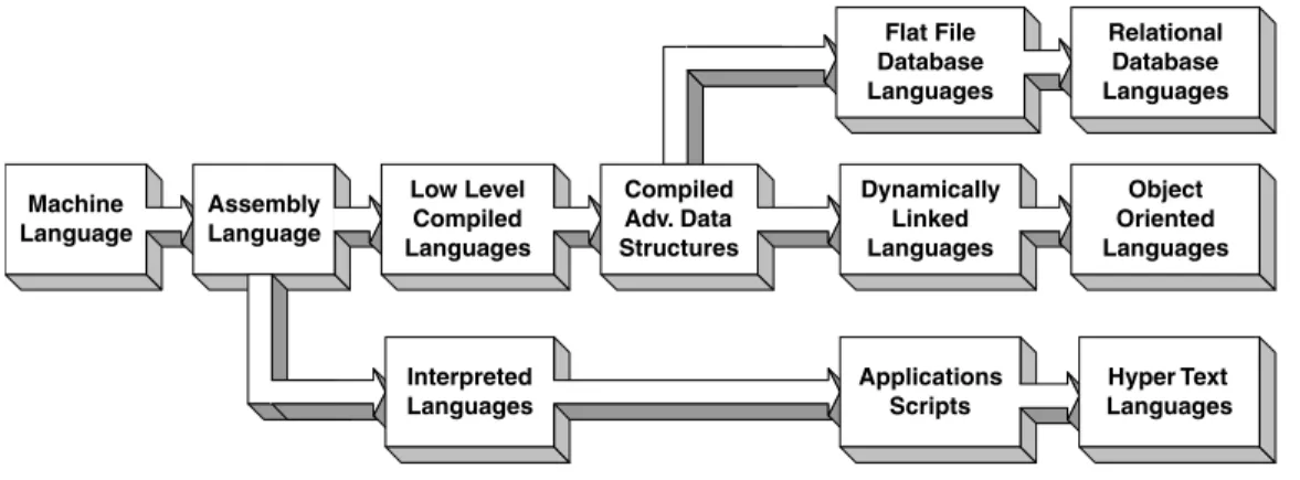
Assembly language
The trade-off between assembly language and higher-level languages is, of course, efficiency versus development time and code maintainability. Still, assembly language is perhaps the best (and sometimes only) means of programming many subsystems of a mobile robot.
Early conventional languages
All geometry functions were specifically written to use the native units of robot encoders. As you become more proficient in an assembly language, you will naturally begin to incorporate many of the concepts of higher-level languages.
Compilers vs. interpreters
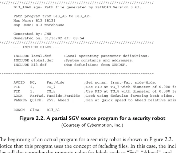
The function's use of the stack to store data meant that for all intents and purposes it could appear as if the function was cloning itself. Although programs like those in Figure 2.2 were originally written by a text editor, later versions were automatically generated by a GUI (Graphical User Interface).
The GUI revolution
The great rift
Object-oriented programming
This allows hundreds of copies of an object to be produced as required by the application. The properties of an object cannot be tampered with from the outside, only by calling a method to set them.
Robots and robot subsystems as objects
Public OriginNode As String 'Original start node Public CurrentNode As String 'Last destination node passed Public LastInsSent As Integer 'Last instruction in current job. Public File Path As String 'Send File Path Public Event Path As String ' Event Log File Path Public Sensor Path As String 'Sensor Log File Path Public Tag Path As String ' Tag/Inventory File Path Public Record Path As String 'Recording File Path .
Network languages
Robots are real-time systems by nature, and trying to program one without an appreciation for the concepts of real-time systems is like playing Sorcerer's Apprentice. The techniques used in real-time software are just extensions of the stack games played with interrupts.
Threads
The beauty of a true real-time system is that it allows writing multiple programs (threads) that look just like conventional programs.
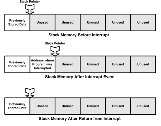
Interrupts and stacks
After subduing the robot by pressing one of the emergency stop buttons, we determined the cause of the event. When the interrupts happened, the robot's program "went into the woodwork" and the robot tried to do the same.
Context
I distinctly remember an occasion where there was a loud disturbance coming from a booth in the testing area of the production floor. I recognized the curses coming from the booth as those of the company artist who was in a very agitated state.
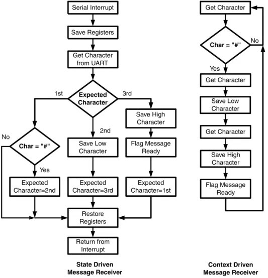
Kernels and tasks
These are usually the values of the CPU's registers and any data already on the stack. For the main program thread, the string on the left side of the figure looks like a regular serial interrupt.
Task switching
For this reason, the interrupt that the context switch causes must remain masked (disabled) until the context is restored. In most systems this is the default and the programmer would have to deliberately re-enable the interrupt to cause a problem.
Interrupt events
Time slicing
Reentrance
Since the function had not completed its work for the first thread before it was called by the second, it is said to have been reintroduced. Therefore, for a routine to reenter, it must only use registers that are stored on its stack, or accumulate memory allocated for its working storage.
Interrupt masking and interrupt priority
What if this encoder service routine itself is interrupted by an interrupt with a longer service cycle? In such a case, the lower priority interrupt will set a latch so that it is served when all the higher priority interrupts have been handled.
Inter-task communications
Such an error may be so small that it is never openly noticed, but the robot's dead reckoning will be significantly degraded. A higher priority interrupt can interrupt a lower priority interrupt handler (or its thread), but the lower priority interrupt is automatically suspended while a higher priority interrupt is handled.
Visual Basic and real-time controls
VB events
DoEvents
DoEvents is an operating system call that transfers control of the CPU to the operating system so that it can determine whether an action event has occurred. If an event has occurred, it is maintained and the CPU returns to continue servicing the original thread.
Freddy as a VB form
One solution to Freddy's problem is for the Unload subroutine to use some sort of timer-type dive loading. The following example will not explain properly because the unload function is executable code.
Modal controls
To fix this problem, simply add the line "exit sub" immediately after the "Unload me" and before the "End if.".
Some other tips on using VB for real-time applications
Setting up a structure
If you will have control over interruptions, decide on the interruption priority order that will ensure that critical services are done first. Decide on the units you will use for distances and angles, and create a basic library of mathematical and geometric functions.
Creating a library
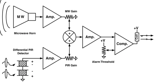
Of all the software concepts covered in this book, fuzzy logic is one of the most valuable and most misunderstood. The circuit of Figure 4-2 shows how we can add the two sensor signals from the motion detector before comparing the result with a threshold value.

Trapezoidal fuzzy logic
Better yet, if we go back to reading the outputs of the two signal amplifiers and perform the balancing, summing and gain thresholding in software, then we have created a true fuzzy logic interference detector. Let us assume that we have digitized the outputs of the detector / amplifiers of Figure 4.2 and scaled them from 0–100%.
Fuzzy democracy
In the case of our motion detector, we decided that we did not want the PIR to contribute to the threat score if it indicated less than 20% of full scale, because signals below this range are commonly perceived as background noise. The highest threat contribution we have allowed for PIR is 80 units, and the highest for MW is 60 units.
Adaptive fuzzy logic
Such a concept is unlikely to be implemented in our society (mainly because the politicians who make laws find charisma easier to make than competence), but fuzzy logic has that ability, and much more. In the coming chapters, we will explore ways in which the results of fuzzy calculations can themselves be inputs to other layers of fuzzy logic.
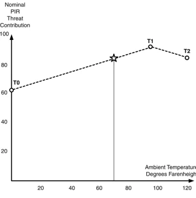
Weighting trapezoids in response to other parameters
To perform the entire transformation, we simply read the temperature, use the graph in Figure 4.4 to determine the nominal threat contribution of the PIR sensor at the current temperature, and then set the contribution value of points P1 and P2 in Figure 4.3 to this value. The star in Figure 4.4 represents the nominal contribution for 70 degrees, the same operating point as used in Figure 4.3.
Multipass and fratricidal fuzzy logic
There, at the very edge of the gas dome, was a ceiling gas heater with a burning pilot light. The console actually issued an alarm stating that it was due to gas with a heavy flame contribution, but since the officer could not smell the gas and did not think of the heater as a flame, he dismissed the threat.
Summary
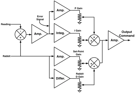
The desired position of the robot or one of its servos is often referred to as the rabbit and. I quickly came to the realization that none of the senior engineers had used such formalities in many years.
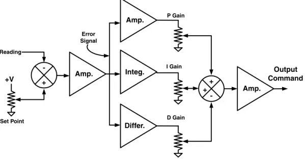
Basic PID controls
The D-term is a signal that is proportional to the lead or the rate of change of the error. A single execution of a PID is often called a tick (like the tick of a clock).
Predictive controls
Thus, this term is proportional to the rabbit derivative, and we will call its gain the rabbit derivative gain or the rabbit speed gain. This term is most commonly found in position controls, and its gain is thus called the rabbit's acceleration gain.
Combined reactive and predictive controls
The second new function is a differentiator that provides a term proportional to the rate of change of the rabbit. When added to the rabbit term, this term gives us a much better guess for the power required during the rabbit transition.
Various PID enhancements
If the error is within this band, the error is multiplied by the gain, otherwise the appropriate error margin is used. First, limit the error to a band for each gain If error > ControlSingles(PBand) Then.
Robot drive controls
This is the speed at which the robot will roll down the ramp in an unpowered state. If the robot tries to move slower than the free movement speed, then the servo will remain in the brake square.
Tuning controls
The integral term must replace the proportional term, and at this point, it is divided by the set point to provide the profit of the rabbit. The profit of the rabbit derivative can then be determined by setting all profits to zero except the rabbit profit.
Rabbits chasing rabbits
Conclusions
Some protocols are only concerned with passing data from one place to another without regard to what it means, while other protocols are concerned with the actual meaning of the data. A protocol or layer of a protocol that deals with the meaning of the data is usually called the application layer or application protocol.
Popular networks
The meaning of the data is determined by the application protocol that is embedded in the network protocol. Only requests and commands supported on both sides of the interface will be available through it.
Basic requirements of the application protocol
The second important requirement for the communication protocol is that it must support the future evolution of the system. It is possible to install special systems on the robot, such as short-range garage door controllers, but these solutions are often problematic due to the one-way nature of the control and limited channel capacity.
Rigid protocols and other really bad ideas
The problem is that we can't predict all the messages we'll eventually need, except for the simplest systems. Unfortunately, a final administrative change came when the RFP (Request for Proposals) was issued for the production of the system.
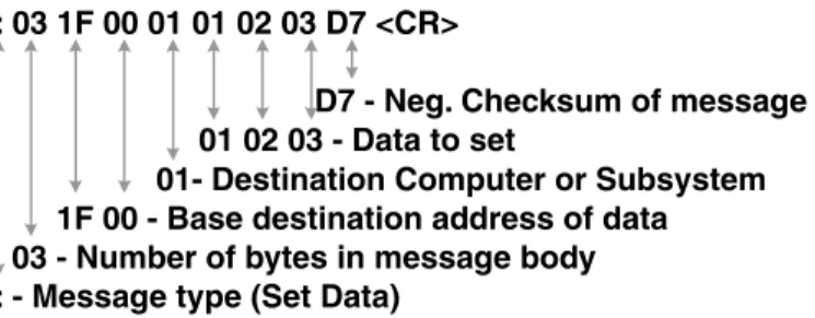
Flexible protocols
If an entire character was lost, the recipient would know that the message was invalid. The messaging protocol for requesting variables from these arrays will simply indicate the array to be accessed, the starting indices, and the number of elements requested.
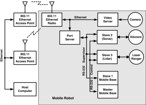
Communications architectures
The supervisory link was taken over by the base station and all computers on the robot responded as slaves. The control link was owned by the mobile base and all other computers were slaves.
Wrappers, layers, and shells
In this case, all computers on the robot serve as slaves on the supervisor connection, which is controlled by the host computer. As the robot moved from location to location, the host computer sent commands to the switch to select the closest video receiver.
Drivers, OCXs and DLLs
If the interface is at the hardware level (such as driving a printer through a serial port), the interface program is usually called a driver. When the interface is at the software level, it is usually in the form of a DLL (dynamically linked library) or an OCX (active-X control object).
Improving communications efficiency
The post office puts all this information in the next empty box and sends the message identification number back to the customer. Another useful method that a post office can provide is the status of the means of communication.
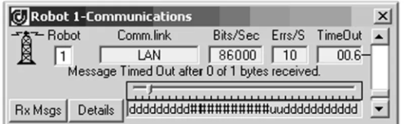
Timing issues and error handling
The result of this exclusive-or is then inserted into the shift register entry. To understand how important this can become, consider that we require the position of the robot.
Other issues
If it hadn't reached a node, the second transmission wouldn't be a problem because the program pointer was still on the first step anyway. However, if you look at the actual robotic products that have been produced, most have used much simpler approximations.
The academic school of thought
For those in the academic camp, robot sensor systems must recognize the entire environment, not just a feature here and there. They envision the robot as perceiving its environment in the same way humans do.
The industrial school of thought
Area coverage robots
At the low end, these robots have incorporated strategies that do not represent true navigation, but rather movement patterns that should ultimately cover the area. For example, lawnmower robots have been developed that randomly cross an area until they detect a boundary marker and then turn away to cross the area again.
Virtual path following vs. goal seeking
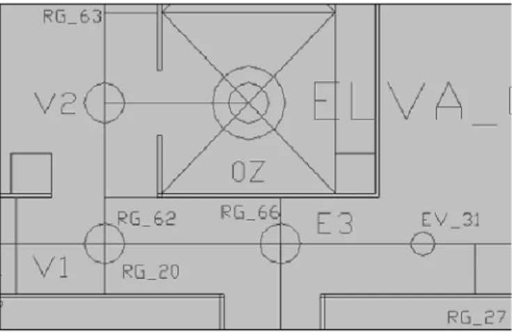
This node refers to all the programs required to operate the elevator and to take the robot from one floor to another. For example, a security robot's route is planned to ensure that the robot performs surveillance in all important areas.
A practical starting point and “a priori” knowledge
Inertial navigation uses accelerometers and gyroscopes as inputs to its calculations, but in the end is a form of dead reckoning. The Luftwaffe therefore developed a ground-based beam system code named "Crooked Leg". The bombers rode a primary pair of beams that provided an indicator showing whether they were straying to the left or right of their intended path to the target.
Target
In navigational terms, the first beams gave the pilot absolute information about the lateral position of the aircraft relative to the intended path, but did not say anything about the longitudinal position along the path. GPS is an extremely powerful tool for outdoor navigation, but this technology also needs to be integrated into the navigation architecture with other techniques.
Understanding why good dead reckoning is crucial
For this reason, Ackerman systems are somewhere between synchronous and slip steer vehicles in terms of the quality of their inherent odometry. If the system does not have good inherent odometry, it is essential to supplement the odometry with appropriate sensors.
Picking coordinate systems
The center of the screen is in the middle of the ship, and its display uses a polar coordinate system. The navigator, on the other hand, calculates and reports the ship's position in latitude and longitude, a spherical system that looks like a Cartesian coordinate system over most of the world (except near the poles).
Tick calculations
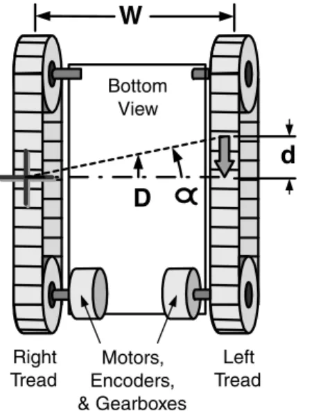
The relative platform motion is a vector of magnitude D at the current heading (θ) of the platform. The angle α is then added to the platform heading to obtain the new heading.
Live reckoning interaction with other processes
In the calculations above, note that the arcsine function is always called with the same value (d/W). This means that the process is dynamic and retains little static information about previous designs.
Path planning and execution
If the robot is only slightly off the path and relatively close to the destination, then the first strategy is fine. On the other hand, if the robot is mostly off the path and far from the destination, the second strategy is appropriate.
Are we there yet?
Thus, at the end of the path, the robot will be consistently oriented parallel to the path. If this is the case, the robot may stop before reaching the end of the path.
Running on
Bread crumbs and irregular path following
The behavior already discussed can be adapted to such routes by moving the rabbit from point to point along the path instead of moving it along the straight line of the path. This can be done by simply running a straight line segment between each of the breadcrumbs.
The Z axis, maps, and wormholes
If the distance between points is too small, the number of points can become unnecessarily large, requiring a lot of memory. The smoothest operation can be achieved when following such a path if you move the rabbit in steps smaller than the distance between the breadcrumbs.
Filtering for the truth
In addition, there may be areas where it is necessary to specify more than one navigation method at a time. For this reason, our navigator may search for several functions at once.
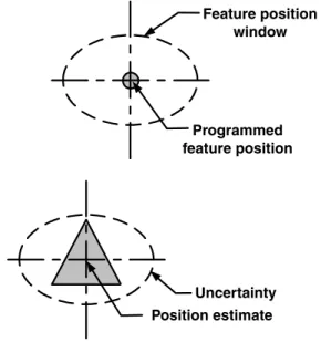
The importance of uncertainty
In Figure 10.1, the robot traveled from the bottom of the screen through nodes Y7, Y8 and then stopped at node Z1. The uncertainty of the corrected axes will be reduced by each of these corrections.
Modeling uncertainty
Heading errors can still occur for a variety of reasons, and this will cause a lateral error as the robot moves. Each time the odometry increases the robot's position estimate by one tap, it can add an appropriate amount to the heading uncertainty accumulator.
Reducing uncertainty
Longitudinal uncertainty is therefore nothing more than the distance traveled multiplied by an error factor. Thus, lateral uncertainty is accumulated by multiplying the distance traveled by the sine of the heading error.
Learning to be accurately uncertain
Uses of uncertainty
We have discussed the importance of knowing uncertainty as a control over the navigation filtering process, but we have yet to consider the mechanism for this control.
Sensor data and maps
In the case of the upper vending machine, the lidar actually reports the reflection "D" from the file cabinet "C" due to these reflections. The glossy paint of the upper file cabinet also causes a small amount of specular reflection "E" because the angle of incidence of the laser beam is so shallow.
Navigation features
Features that are added to the environment for navigation purposes are called fiducials or fids. Since they had defeated the German beam systems, the British sought a stronger solution to the navigation problem.
Hard navigation
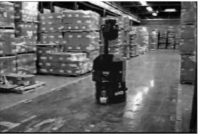
However, when we turned the robot loose in the customer's facility, it weaved its way down the halls like a drunken sailor. There were several places where the robot was forced to drive a short distance without any navigational corrections.
The concept of fuzzy navigation
To do this, we calculate the reliability of the heading correction or the azimuth quality of the implied correction. To compensate for the heading error, we find the vector from the center of our position estimate to the measured center of column A′.
Other profiles
Initially, most improvement would be in the azimuth (the most important degree of freedom), then in the lateral position, and then, somewhat more slowly, the longitudinal position. This would be because the corrections in the azimuth will reduce the azimuth uncertainty, which will increase the observation quality for the position measurements.
The referenced state
If the robot's uncertainty estimate is less than the actual position error, the navigation agents will reject all position corrections. In reality, the uncertainty of the robot is never zero, and the uncertainty estimate should reflect this fact.
Sensor types
The second bad assumption of the ring configuration is that the narrow beam of the transducer provides the angular resolution for the returned range data. The trick is for the robot to have a priori knowledge of the position and azimuth of the wall.
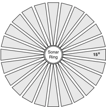
Guidelines for selecting and deploying navigation and collision avoidance sensors
In the models in Figure 12.6, there are 12 possibilities for a wall to be within range of the transducers and not be seen. The beam patterns of these transducers were set to be cross-eyed in order to provide double coverage in front of the robot.