The publisher assumes no responsibility for any injury and/or damage to persons or property due to products liability, negligence or otherwise, or from any use or operation of any methods, products, instructions or ideas contained in the material herein. A catalog record for this book is available from the British Library of Congress Cataloging-in-Publication Data.
Preface
Basic electrical engineering principles
1 Units associated with basic electrical 1
- SI units
- Charge
- Work
- Power
- Electrical potential and e.m.f
- Resistance and conductance
- Electrical power and energy
- Further problems on units associated with basic electrical quantities
- Summary of terms, units and their symbols
The unit for work or energy is the joule (J), where one joule is one newton meter. The unit of electric potential is the volt (V), where one volt is one joule per coulomb.
2 An introduction to electric circuits 1
- Standard symbols for electrical components Symbols are used for components in electrical circuit dia-
- Electric current and quantity of electricity All atoms consist of protons, neutrons and electrons
- Further problems on electric current and quantity of charge
- Potential difference and resistance
- Basic electrical measuring instruments An ammeter is an instrument used to measure current and
- Linear and non-linear devices
- Ohm’s law
- Multiples and sub-multiples
- Further problems on Ohm’s law 1. The current flowing through a heating element is
- Conductors and insulators
- Electrical power and energy Electrical power
- Further problems on power and energy
- Main effects of electric current The three main effects of an electric current are
- Fuses
- Further problem on fuses
A current of 5 A flows through the winding of an electric motor, while the resistance of the winding is 100. Determine the power dissipated by the element of an electric fire with resistance 20 at a current of 10.

3 Resistance variation 1
Resistance and resistivity
If the wire is stretched until its cross-sectional area is 1 mm2, determine the resistance of the wire. Calculate the resistance of a 2 km length of aluminum overhead power cable if the cross-sectional area of the cable is 100 mm2.
Further problems on resistance and resistivity
- Temperature coefficient of resistance
If the temperature coefficient of resistance of copper at 20◦C is 0.004/◦C, determine the resistance of the coil when the temperature rises to 100◦C. If the temperature coefficient of resistance of aluminum is 0.0039/◦C at 18◦C, determine the temperature to which the coil is raised.
Further problems on temperature coefficient of resistance
4 Batteries
- Introduction to batteries
- Some chemical effects of electricity
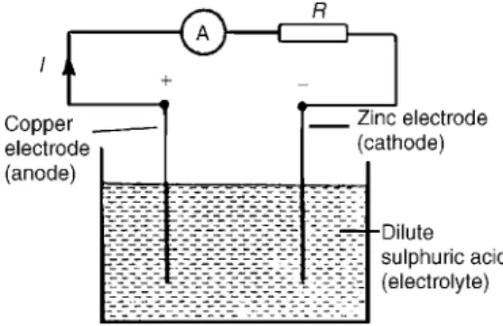
- The simple cell
- Primary cells
- Secondary cells
- Safe disposal of batteries
- Fuel cells
- Alternative and renewable energy sources Alternative energy refers to energy sources which could
When a current flows in the direction shown in Figure 4.2, the cell is said to discharge (E>V. For the circuits shown in Figure 4.5, the resistors represent the internal resistance of the batteries.
Revision test 1 1
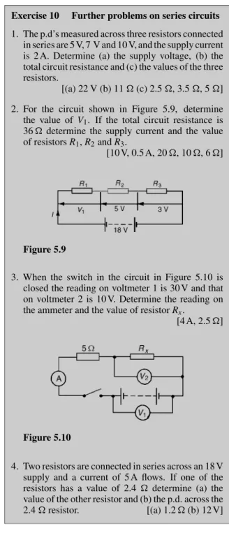
5 Series and parallel networks
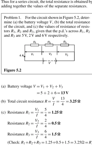
- Series circuits
- Potential divider
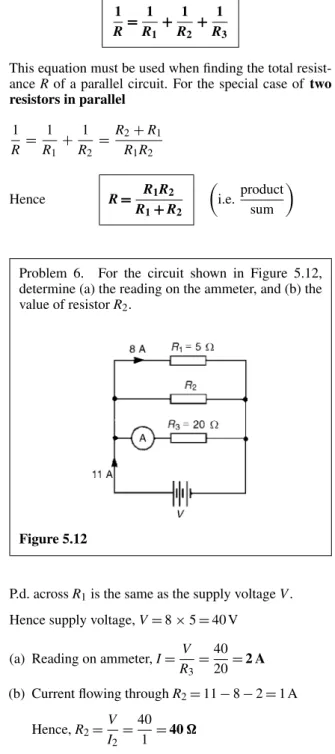
- Parallel networks
- Current division
- Further problems on parallel networks
- Relative and absolute voltages
- Further problems on relative and absolute voltages
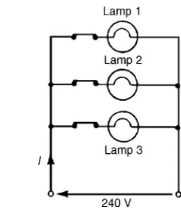
- Further problems on wiring lamps in series and parallel
For the circuit shown in Figure 5.26, determine (a) the reading on the ammeter and (b) the value. For the circuit shown in Figure 5.34, calculate (a) the voltage drop across the 7 resistor, (b) the current through the 30 resistor, (c) the power developed in the 8 resistor, (d) the voltage at point X w.r.t.
6 Capacitors and capacitance 1
- Introduction to capacitors
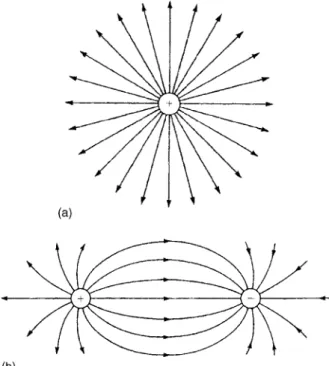
- Electrostatic field
- Electric field strength
- Capacitance
- Capacitors
- Further problems on charge and capacitance
- Electric flux density
- Permittivity
- Further problems on electric field strength, electric flux density and permittivity
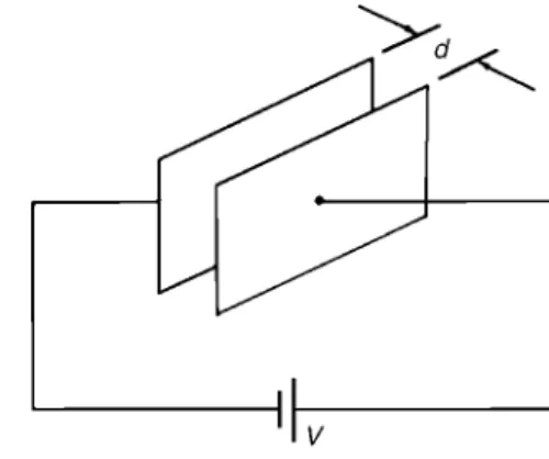
- The parallel plate capacitor
- Further problems on parallel plate capacitors (Where appropriate take ε 0 as
- Capacitors connected in parallel and series (a) Capacitors connected in parallel
- Further problems on capacitors in parallel and series
- Dielectric strength
- Energy stored
- Further problems on energy stored (Where appropriate take ε 0 as 8.85 × 10 −12 F/m)
- Practical types of capacitor
- Discharging capacitors
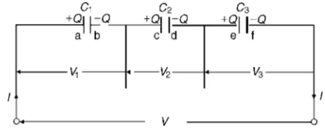
It follows that for n parallel connected capacitors, C=C1+C2+C3· · ·+Cn. the equivalent capacitance of a group of capacitors connected in parallel is the sum of the capacitances of the individual capacitors. Determine (a) the equivalent circuit capacitance, (b) the total charge, and (c) the charge on each capacitor. a) The equivalent capacitance C for four capacitors in parallel is given by:.
7 Magnetic circuits
- Introduction to magnetism and magnetic circuits
- Magnetic fields
- Magnetic flux and flux density
- Magnetomotive force and magnetic field strength
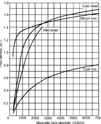
- Permeability and B–H curves
- Reluctance
- kA/Wb Absolute permeability, µ = µ 0 µ r = (4π × 10 −7 )(4000)
- Further problems on magnetic cir- cuits (Where appropriate assume
- Composite series magnetic circuits
- Further problems on composite series magnetic circuits (Where appropriate assume
- Comparison between electrical and magnetic quantities
- Hysteresis and hysteresis loss
What is the flux density in a magnetic field with a cross section of 20 cm2 and a flux of 3 mWb. Determine the flux density over a 2 cm path if the relative permittivity of the cast steel is 750. Hysteresis is the effect of "lag" the flux density B whenever there are changes in the magnetic field strength H.
Revision test 2 1
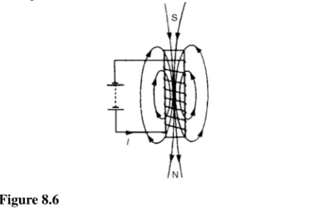
8 Electromagnetism
- Magnetic field due to an electric current Magnetic fields can be set up not only by permanent mag-
- Force on a current-carrying conductor If a current-carrying conductor is placed in a magnetic
- Further problems on the force on a current-carrying conductor
- Principle of operation of a simple d.c. motor A rectangular coil which is free to rotate about a fixed
- Principle of operation of a moving coil-instrument
- Force on a charge
- Further problems on force on a charge
If the length of the conductor in the field is 30 cm, calculate the force acting on the conductor. If the conductor is vertical, the current flowing downwards, and the direction of the magnetic field is from left to right, what is the direction of the force. If the length of the conductor in the field is 200 mm, calculate the force acting on the conductor.
9 Electromagnetic induction
- Introduction to electromagnetic induction When a conductor is moved across a magnetic field so as
- Laws of electromagnetic induction
- Rotation of a loop in a magnetic field
- Further problems on induced e.m.f
- Inductance
- Inductors
- Energy stored
- Further problems on energy stored 1. Calculate the value of the energy stored when a
- Inductance of a coil
- Further problems on inductance of a coil
- Mutual inductance
- Further problems on mutual inductance
Determine (i) the direction in which the conductor must be moved in Figure 9.4(a), (ii) the direction of the induced e.m.f. If the flux on the pole face is 60 mWb, find the magnitude of the induced e.m.f. Determine (a) the mutual inductance of the two coils, (b) the reluctance of the former, and (c) the self-inductance of the secondary coil.

10 Electrical measuring instruments and measurements
Introduction
Analogue instruments
The scale is tight at first and the scaling is uneven across the range.
Moving-iron instrument
The moving-coil rectifier instrument A moving-coil instrument, which measures only
Comparison of moving-coil, moving-iron and moving-coil rectifier instruments
Shunts and multipliers
So that the moving coil instrument is used as an ammeter with a range of 0–50 A, a value of resistance. Calculate the value of the multiplier to be connected in series with the instrument so that it can be used as a voltmeter for measuring p.d. to 100 V. So that the moving coil instrument can be used as a voltmeter with a range of 0–100 V, a resistor of value 12.49 k must be connected in series with the instrument.
Further problems on shunts and multipliers
- Electronic instruments
- The ohmmeter
- Multimeters
- Wattmeters
- Instrument ‘loading’ effect
Calculate the value of the shunt that must be connected in parallel with the meter so that it can be used as an ammeter for measuring currents up to 50 A. Calculate the value of the multiplier that must be connected in series with the instrument so that it can use is used as a voltmeter for measuring p.d.s up to 200 V. When the voltmeter is connected across the 40 k resistor, the circuit is as shown in Figure 10.12(a) and the equivalent resistance of the parallel network is given by .
Further problems on instrument
- The oscilloscope
Together, the horizontal sweeping action (ie the X direction) and the vertical deflection action (ie the Y direction) trace a graph of the signal on the screen. A sinusoidal voltage trace displayed by an oscilloscope is shown in Figure 10.19. a) The width of a complete cycle is 4 cm. Electrical measuring instruments and measurements 91. a) The width of each complete cycle is 5 cm for both waveforms.
Further problems on the oscilloscope 1. For the square voltage waveform displayed on an
- Virtual test and measuring instruments Computer-based instruments are rapidly replacing items
- Virtual digital storage oscilloscopes Several types of virtual DSO are currently available
- Waveform harmonics
- Logarithmic ratios
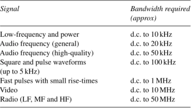
It is worth noting that most manufacturers define the bandwidth of an instrument as the frequency at which a sine wave input signal will drop to 0.707 of its true amplitude (i.e. the -3 dB point). So, x is the third harmonic of the signal 'o'. c) The amplitude of the second harmonic (shown at about 2270 kHz)= −5 dB. i) Let an instantaneous voltage v be represented by v=Vmsin 2πft volts. In Figure 10.29(c) the negative cycle appears as a mirror image of the positive cycle around point A.
Further problems on logarithmic ratios
- Null method of measurement
- Wheatstone bridge
- D.C. potentiometer
E1 the slider S moves along the slider wire until equilibrium is reached (ie the galvanometer deflection is zero), shown as length l1. The potentiometer may be arranged as a resistive two-element potential divider in which the division ratio is adjustable to give a simple variable d.c. Such devices can be made in the form of a resistive element with a sliding contact, which is adjusted by rotary or linear movement of the control knob.
Further problems on the Wheatstone bridge and d.c. potentiometer
- A.C. bridges
- Measurement errors
Each instrument has a margin of error which is expressed as a percentage of the instruments full scale deviation. Determine the resistance of the resistor and the accuracy of its measurement if both instruments have a margin of error of 2% of the f.s.d. The maximum relative error of Rx is given by the sum of the three individual errors, i.e.
Further problems on measurement errors
The current I flowing through a resistor R is measured with an ammeter of 0–10 A, which gives an indication of 6.25 A.
11 Semiconductor diodes
- Types of material
- Semiconductor materials
- Conduction in semiconductor materials Arsenic, antimony and phosphorus have five valency elec-
- The p-n junction
- Forward and reverse bias
- Further problems on semiconductor materials and p-n junctions
- Semiconductor diodes
- Characteristics and maximum ratings Signal diodes require consistent forward characteristics
- Rectification
- Zener diodes
- Silicon controlled rectifiers
- Light emitting diodes
- Varactor diodes
- further problems on semiconductor diodes
When the materials are joined, some of the mobile electrons in the n-type material are distributed to the p-type material. Also, some of the mobile holes in the p-type material diffuse into the n-type material. Due to the repulsion of like charges, the holes in the p-type material move towards the junction.

12 Transistors 1
- Transistor classification
- Bipolar junction transistors (BJT)
- Transistor action
- Leakage current
- Bias and current flow
- Transistor operating configurations
- Bipolar transistor characteristics
- Transistor parameters
- Current gain
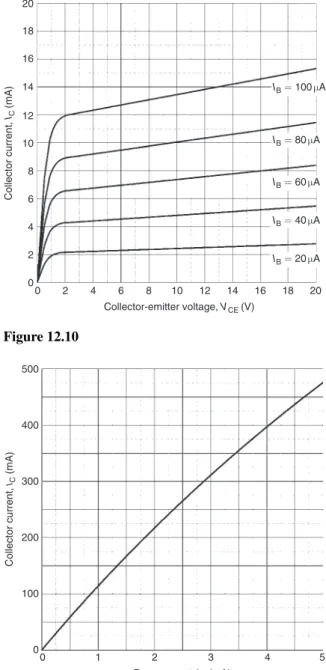
- Typical BJT characteristics and maximum ratings
- Further problems on bipolar junction transistors
- Field effect transistors
- Field effect transistor characteristics A typical mutual characteristic (I D plotted against V GS )
- Typical FET characteristics and maximum ratings
- Load lines
- Further problems on transistors 1. State whether the following statements are true or
In an n-p-n transistor connected as shown in Fig. 12.4(a), the operation of the transistor is considered as follows: a) the principal carriers in the n-type emitter material are electrons. In a p-n-p transistor connected as shown in Fig. 12.4(b), the operation of the transistor is considered as follows: a) the main carriers in the p-type emitter material are holes. The slope of this curve (ie, the ratio of IC to IB) is the common-emitter current gain of the transistor, which is explored in more detail in Section 12.9.
Revision test 3 1
Main formulae for Part 1
Electrical principles and technology
13 D.c. circuit theory
Introduction
Kirchhoff’s laws Kirchhoff’s laws state
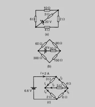
This is shown in Figure 13.5 where the three branch currents are expressed in terms of I1 and I2 only, since the current through R is I1+I2. From loop 1 of figure 13.5, and moving in a clockwise direction as indicated (the direction chosen does not matter), gives For the bridge network shown in Figure 13.9, determine the currents in each of the resistors.
Further problems on Kirchhoff’s laws
- The superposition theorem The superposition theorem states
Label the currents in each branch and their directions as shown in Figure 13.17(a) and determine their values. Label the currents in each branch and their directions as shown in Figure 13.18(a) and determine their values. For the circuit shown in Fig. 13.21, using the superposition theorem, find (a) the current flowing and the p.d.
Further problems on the superposi- tion theorem
- General d.c. circuit theory
- Thévenin’s theorem Thévenin’s theorem states
Use Thévenin's theorem to find the current flowing in the resistor for the circuit shown in Figure 13.34(a). ii). Use Thévenin's theorem to determine the current I flowing in the 4 resistors shown in Figure 13.36(a). Use Thévenin's theorem to determine the current flowing in the resistance of the network shown in Figure 13.37(a).
Further problems on Thévenin’s theorem
- Constant-current source
- Norton’s theorem Norton’s theorem states
Use Thévenin's theorem to find the current flowing in the 6 resistor shown in Figure 13.40 and the power dissipated in the 4 resistor. For the bridge network shown in Figure 13.42, find the current in the 5 resistor and its direction using Thévenin's theorem. Use Norton's theorem to determine the current in the 3-resistor of the network shown in Figure 13.46(a).
Further problems on Norton’s theorem
- Thévenin and Norton equivalent networks The Thévenin and Norton networks shown in Figure 13.49
The resistance 'looking in' at terminal AB is 2. Therefore, the equivalent Norton network is as shown in Figure 13.53. Determine by successive conversions between Thévenin and Norton equivalent networks a Thévenin equivalent circuit for terminals AB of Figure 13.57(a). Thus, the Thévenin equivalent circuit for terminal AB of Figure 13.57(a) is as shown in Figure 13.57(e).
Further problems on Thévenin and Norton equivalent networks
- Maximum power transfer theorem The maximum power transfer theorem states
Both of the Norton equivalent networks shown in Figure 13.57(c) can be converted to Thévenin equivalent circuits. Determine, by successive conversions between Thévenin and Norton equivalent networks, a Thévenin equivalent circuit for the terminals AB of Figure 13.61. Therefore, in Figure 13.62, when R=r the power transferred from the source to the load is a maximum.
Further problems on the maximum power transfer theorem
14 Alternating voltages and currents
- Introduction
- The a.c. generator
- Further problems on frequency and periodic time
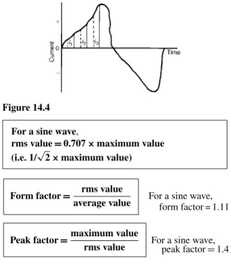
- A.c. values
- Further problems on a.c values of waveforms
- The equation of a sinusoidal waveform In Figure 14.8, OA represents a vector that is free to rotate
- Further problems on the equation of a sinusoidal waveform
- Combination of waveforms
- Further problems on the combination of waveforms
- Rectification
Find (a) the rms voltage, (b) the frequency, and (c) the instantaneous value of the voltage when t=4 ms. a) The general expression for an alternating voltage is v=Vmsin(ωt±φ). Express the instantaneous voltage in the formv=Vmsin(ωt±φ). circuit at any time t seconds is given by: . a) the peak value, the periodic time, the frequency and the phase angle relative to 120 sin 100πt. The instantaneous value of voltage in an alternating current. circuit at any time t seconds is given by: . a) the peak-to-peak voltage, the periodic time, the frequency and the phase angle.
Revision test 4
- Purely resistive a.c. circuit
- Purely inductive a.c. circuit
- Further problems on purely inductive and capacitive a.c. circuits
- Further problems on R–L series a.c
- Further problem on R–C series a.c
- Series resonance
- Q-factor
- Further problems on series resonance and Q-factor
- Bandwidth and selectivity
- Power in a.c. circuits
- Power triangle and power factor
- Further problems on power in a.c
- Introduction
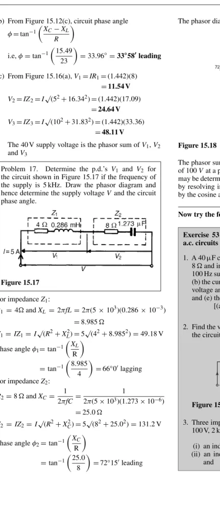
Calculate (a) the current flowing, (b) the phase difference between the supply voltage and the current, (c) the voltage across the coil and (d) the voltage across the capacitor. Calculate (a) the circuit impedance, (b) the current flowing, (c) the phase angle between voltage and current, (d) the voltage across the coil, and (e) the voltage across the capacitor. Find (a) the current flowing, (b) the phase angle of the circuit, (c) the resistance, (d) the impedance, and (e) the inductance.