First, I would like to thank the Honors College, the Department of Electrical Engineering, and the Department of Computer and Information Sciences for their collaboration in funding my trip to present my work at the Design Automation Conference. The exposure to the field of design automation was invaluable to my project and my future studies. Finally, I would like to thank my parents for nurturing my love for science throughout my life.
Nanomagnet Logic is a new technology for low-power, highly scalable implementation of quantum-dot cellular automata. Determining whether feedback is possible is critical to assessing the robustness of nanomagnet logic in any pipelined computer design. Therefore, development of a quantitative approach for the verification of feedback pathways is essential for the development of design and synthesis tools for nanomagnetologic structures.
A set of definitions for canonical alignment and state definitions for NML paths are presented, as well as mathematical operations for determining the resulting states. The simulation results are presented for quantification of the NML magnetization angles for horizontal, vertical, negative-diagonal, and positive-diagonal geometric alignments. The presented framework can be used as a basis for defining a representation of signal propagation for the design and verification of robust NML devices and prevent deadlocks due to incorrect implementation.
INTRODUCTION
However, because the energy difference between the Up and Down states can be very large, NML requires an external clock field to re-evaluate the nanomagnet states for new inputs [10]. External clock fields are divided into discrete areas called clock zones, which monitor small neighborhoods of nanomagnets to avoid errors and better control data propagation [11]. Regulating bistable NML fields using external clock fields will enable efficient implementation of sequential QCA devices, especially in implementations where power dissipation can be exploited, such as Differential Power Analysis [12].
However, the quantification of the implications of external clock fields in pipeline elements has only been investigated in a few cases [16-22] because the NML technology is not yet mature. This paper presents a framework for quantifying signal propagation along NML wires composed of square nanomagnets in sequential designs, with the primary goal of verifying sequential NML circuits. The framework verifies the logical correctness and support of consecutive elements, given a set of clock zones.
The model reflects the behavior of general NML circuits with high fidelity, operation and circuit. In Section IV, simulation data are used to establish the basis for a computational model of the sequential NML and are able to represent the adjacencies and logical states of square and rectangular nanomagnets.
NML DEVICES AND PREVIOUS WORK
Given a phase diagram, ranges of magnetization angles are mapped to the Up, Down and Metastable states. By appropriately placing nanomagnets, NML structures can be built that define such stable states and behave in accordance with Boolean algebra and digital circuits. Due to the additive nature of the magnetic fields, nanomagnets behave according to a majority voter function.
Given a set of neighboring magnets, the most stable state of a nanomagnet will match the state held by most of its neighbors. In case of a tie, both Up and Down will be equally stable; so a rectangular nanomagnet will randomly choose between the two. Alternatively, AND and OR operators can be constructed using trapezoidal magnets which are effectively biased towards one state [29].
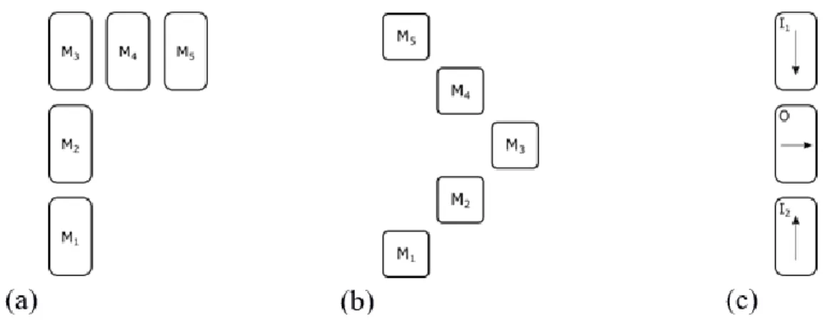
In this example, clocking zones are bounded horizontally and extend vertically along the entire length of the circuit. The crossover is implemented with an ensemble of five square nanomagnets arranged in a cross pattern. The resulting alignment between the square magnets and any coupled rectangular magnets will also be 45° instead of 90° and 0°.
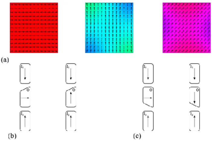
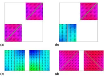
The square magnets will still behave according to a majority function, polarizing in the direction that minimizes the total energy, but a model of NML must be able to represent polarization and alignment in all eight directions. Examples of coupled square and rectangular alignments, as well as trapezoidal implementations of AND and OR gates, are shown in Figure 4. Nanomagnets do not easily switch between the Up and Down states due to the significant energy difference between the two.
To reevaluate an NML circuit on new inputs, an external clock field must force the nanomagnets into the metastable state before they settle into the correct state. To minimize errors, this clocking mechanism should be applied to small sets of nanomagnets in sequence rather than all at once [26]. Clock zones are single, continuous areas that contain the array of nanomagnets in a logical structure whose clock fields are activated simultaneously.
Thus, the order in which zones are clocked affects the direction in which data flows and the order in which logic is applied. Our model must account for this clock sequence and how it affects other features of the circuit.
![Figure 2: (a) NML circuit with 2 inputs and 1 output, divided into clocking zones according to a standard cell library as described in [30]](https://thumb-ap.123doks.com/thumbv2/123dok/10462395.0/13.918.263.716.104.398/figure-circuit-divided-clocking-according-standard-library-described.webp)
SIMULATION PROCEDURE
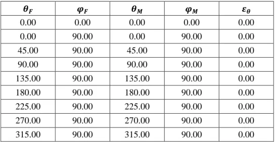
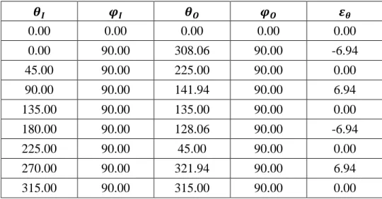
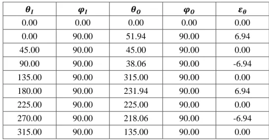
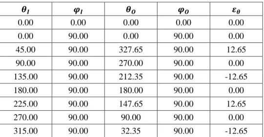
The primary simulations are of two-magnet circuits with one input magnet and one output magnet. The simulations of single magnets are used as a source of constants to be used in later calculations. Given an input magnet, an output magnet can be in one of the eight surrounding grid cells; and there is a line passing through the nearest corners of each magnet.
These alignments are defined as Horizontal, Vertical, Positive-Diagonal and Negative-Diagonal respectively; and we defined these as canonical alignments. Each canonical alignment has two corresponding canonical states, each pair being additive inverses that extend along a canonical alignment in opposite directions. Our goal with these simulations is to identify how, given an input state, the alignment between two magnets changes the output state induced by the input magnet in an ideal environment.
In all cases, the mean magnetization of the total system in A/m is recorded and includes the contribution from free space and is not normalized. The presented simulations use cobalt composite nanomagnets with a saturation magnetization of 106 A/m and an exchange stiffness constant of 1.3×10⁻¹¹ J/m. The horizontal and vertical distances between the nanomagnets are both 9 nm, and the diagonally placed nanomagnets are 9√2 nm apart at the nearest corners.
The two-magnet systems have mesh cells that act like a vacuum, and the single-magnet systems have no vacuum cells. The input state is set by a uniform magnetic field of 100 mT in the direction of the desired canonical state. It is strong enough to both set the input state and keep that state constant during the simulation.
This field is bounded by the edges of the input magnet in the xy plane. Tests were performed for nine canonical input states for single magnets and all nine were tested against four proposed canonical alignments of interest for a total of forty-five unique cases.
SIMULATION AND CALCULATION RESULTS
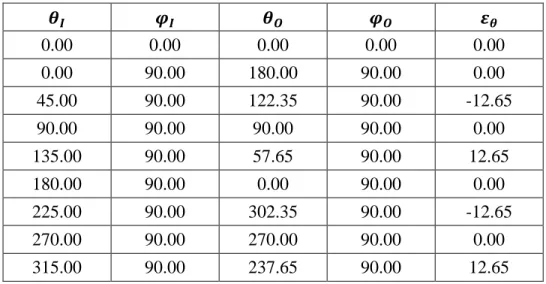
After calculating the average magnetization of the output magnets, the output states are converted and canonical states to spherical coordinates. The single-magnet simulations presented were highly consistent with standard deviations generally ranging from A/m to 1.18×10⁻⁶ A/m. All data for the z-component of magnetization and the data for the test case 𝜃 = 0, 𝜑 = 0 showed no deviation.
APPLICATION OF RESULTS
The input magnet is on the left, and the output magnet is on the right. The data streams are represented as matrix multiplication where the alignment matrix M corresponds to the magnet alignment and transforms the state vector S based on our simulation results. Using the state representation given by (2) thus yields the horizontal and vertical alignment matrices (3) and (4).
For example, horizontal wires are known to invert vertical states [28]; and our simulations demonstrated this behavior. Simulation data show that this reversal also holds for diagonal states, although less stable for straight-edge square magnets. Thus, the stretching matrices 𝐷𝑃 and 𝐷𝑁 can also be defined for diagonal alignments, although they are not as easily factorized.
Thus, we can approximate data propagation along an NML thread using multiplication of 9x9 matrices and a 9-element column vector.
CONCLUSION
Niemier et al., “Boolean logic through patterned magnetic dots with bevelled edges,” IEEE Trans.