Without solving a significant portion of the biochemical problems for the RNAP effort, my candidacy would have been a lot of fun. I'm extremely grateful for the two sleepless weeks we spent getting the potential shaping experiment to work.
Preamble
Background and Motivation 1.1 Introduction
Commentary
Unless there is a major discovery about how the mind works and how it can be manipulated, it is doubtful that any medical advances through greater understanding of biological systems will affect these problems. While we hope that the research efforts here will benefit more than just the career goals of the author, the greatest contribution anyone can make is to give what you have and be aware of the consequences of your actions.
Using population health as a yardstick, it's humbling to realize that for all the technological progress we've made, it hasn't had nearly as much impact as just two, refrigeration and septic practices like sewage treatment. Ludecke, H.J., et al., Cloning of defined regions of the human genome by banded chromosome microdissection and enzymatic amplification.
Nanometer Control
Digital Signal Processor-Based Feedback Control and Data Acquisition
Introduction
The author has also attempted to address many of the problematic grounding issues observed in current commercial data acquisition hardware. These new processors have 64-bit double precision floating point with some limitations to take full advantage of the processor speed.
DSP Lament
To use DSPs correctly requires little more than a basic knowledge of signal processing techniques. But they are focusing efforts on 16-bit product lines first because of demand from wireless applications.
Goals of the DSP Design
The fidelity of the measured signal must be maintained to the A/D inputs. Then there is the final insert at the heart of the attempt to perform measurements with high sensitivity, the case is connected to the grounding system of the power grid.
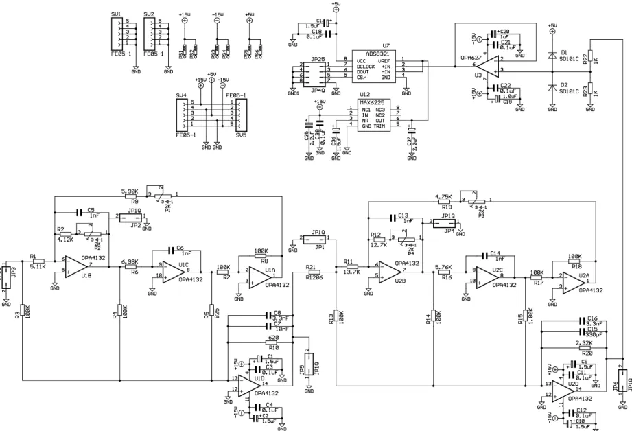
The Design
Detailed schematics, parts lists and table layout images can be found in the appendix. The software tools are free, fulfilling another design goal for the cost of the final system.
The hardware cost is in the same range as a high-end data acquisition card using 16-bit converters even if the contract is mounted.
Electronic Q Control of SPM Microcantilevers 3.1 Introduction
Description of Method
From this we can see that by changing b, the Q of the system can be changed. This implies that we can change the effective temperature of the cantilever by changing the damping term. So by changing the effective temperature, you also change the mean square amplitude of the cantilever due to thermal fluctuations and improve the noise floor of the z.
This is a simplification because the other vibration modes of the cantilever are not completely orthogonal and contribute to the movement in the z-axis [8, 9]. However, they do not appear to be the main component of the thermally induced motion we are trying to evaluate.
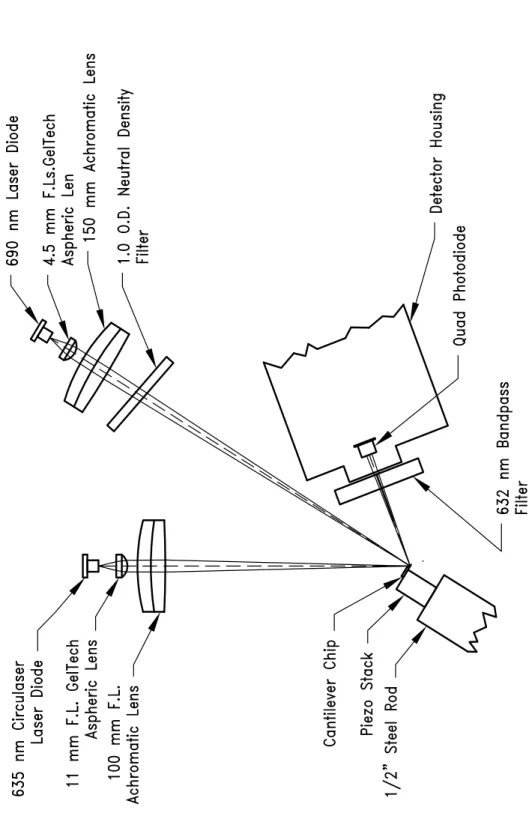
Experimental setup
The 635 nm laser diode and quad photodiode implement a typical optical lever to measure the tip deflection of the cantilever. A laser diode and quad photodiode implement an optical lever to measure the z-displacement of the cantilever. This place is positioned to be as close as possible to the end of the console.
The Circulaser contains a cylindrical microlens in the diode housing that is very close to the output of the laser diode. The collimated beam is then focused by a 150 mm focal length achromat (Edmund Scientific) onto the center of the cantilevered beam.
Results and Discussion
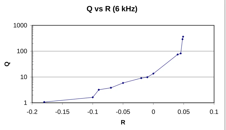
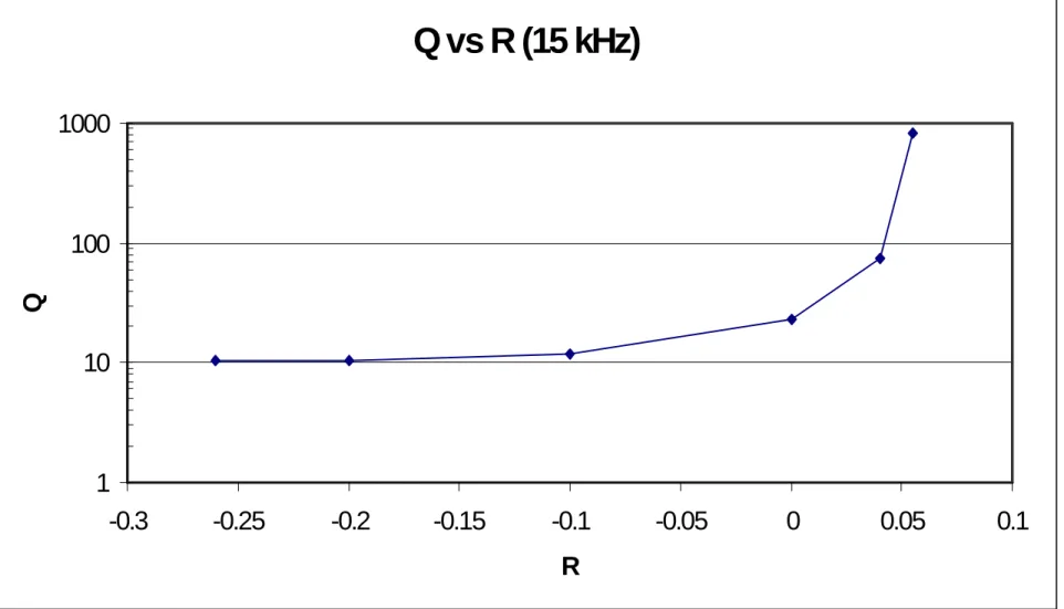
The central curve is the natural resonance of the cantilever in air, i.e., the coefficient is zero. 6 kHz cantilever response spectrum for extremes of R centered at cantilever resonance. 15 kHz cantilever response spectrum for R space centered at the cantilever resonance.
0–50 kHz spectra of the 6 kHz cantilever for several R coefficients tested on this cantilever. 0–50 kHz spectra of the 15 kHz cantilever for several R coefficients tested on this cantilever.

Conclusions
Sculpting Nanoscale Potentials with Optical Tweezers and Digital Feedback
Introduction
The shape of the outline must be describable by a vector from the center of the trap that does not cross any of the perimeter boundaries when rotated to outline the entire outline. Because optical tweezers confine particles to nanometer-scale areas, the technique provides a method to manipulate a particle with nanometer resolution without moving its beam or optics. The technique has applications for directing chemical or physical interactions at the nanometer scale and imaging methods at the same scale.
Theoretical Background
To trap a particle, the trapping potential must be greater than the thermal forces, which would otherwise push a particle out of the trap. Because the restoring spring force is proportional to the intensity of the light trap, the root mean square (RMS) amplitude can be changed by changing the intensity of light. If the position of a particle in a light trap is monitored, the location of the potential wall can be adjusted depending on the particle's position.
In the experimental work presented here, the x-y position in the above plane of a captured polystyrene bead was measured and the intensity of the captured light was varied according to a map. If the bead crossed the map boundary, the laser intensity was increased to the maximum value, pushing the bead back to the center of the light trap.
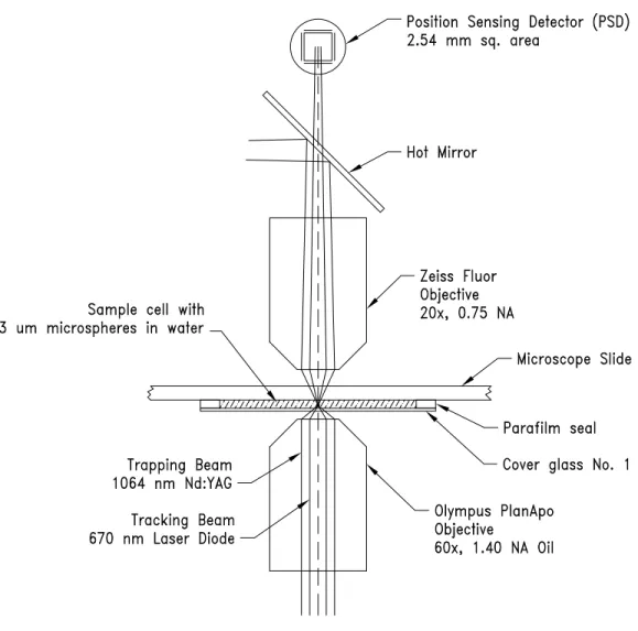
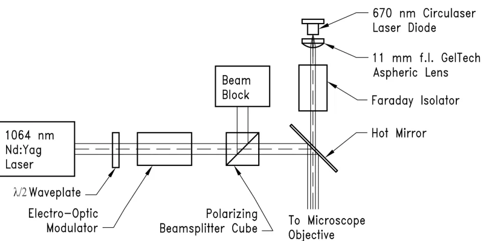
Experimental Setup
The sample cell is filled by injecting the liquid containing the microspheres into the open end of the assembly. A second red laser diode (BlueSky Research Circulaser λ=670 nm 10 mW max.) is used to measure the position of the trapped bead. Because the intensity of the trapping laser is modulated, it becomes difficult to use for monitoring the bead position.
Instead, the collection target is adjusted until the beam fills approximately 50% of the detection area of the linear PSD. The translation resolution is roughly the spot diameter divided by the noise floor of the photodiode and its electronics.
Results and Discussion
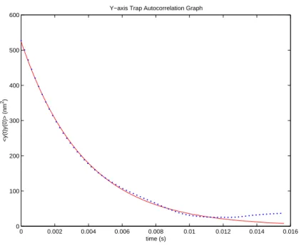
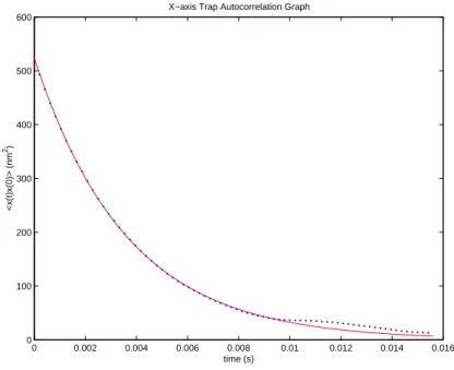
By obtaining the numerical autocorrelation of the recorded x-y locations of the trapped bead at a fixed laser power level, the time constant τ can be determined by least square. Figures 4.8 and 4.9 show plots of the numerical autocorrelation and line of best fit with the initial 800 data points of the autocorrelation score for the x and y axes. At lower capture laser power levels, the effect of tracer beams should be more significant.
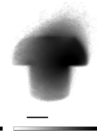
However, it does not eliminate the apparent critical alignment of the capture beam, tracking beam, and collection optics. There is also the annoying problem that the hot spot is not in the center of the "T" shape.
Conclusions and Additional Discussion
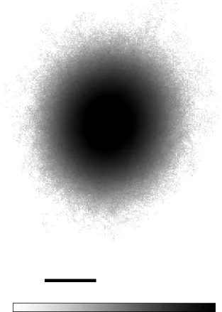
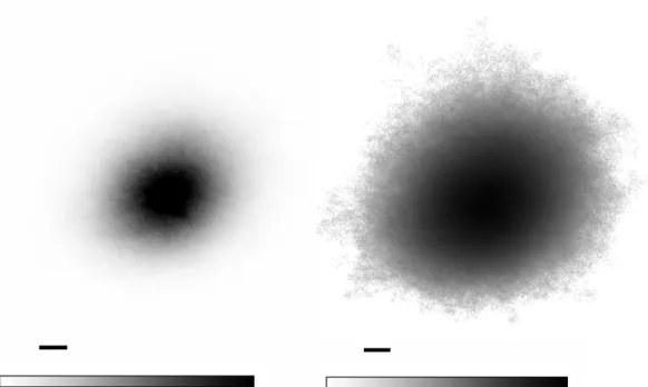
Based on the above equation, it can be argued that the logarithm histograms presented here represent the time-independent potential of the potential well created by this technique. Although it was hoped that they would appear flatter than what is shown here, a significant result is the steepness of the edges of the potentials. This is improved compared to the fixed laser power images used to measure the spring constant of the potentials.
The above interpretation is reasonable provided the feedback of the control system is high enough, otherwise the potential created by this technique is time dependent. Other applications would be directed molecular interactions where the microsphere is coated with a compound to interact with a surface.
It is difficult to imagine a way to implement these shaped capabilities without the availability of high-speed digital signal processors and fast, high-resolution A/D converters.
Microfluidic Manipulations
Introduction
The work in Chapter 6 was published in the Proceedings of the National Academy of Sciences USA.
A Microfabricated Fluorescence-Activated Cell Sorter
- Introduction
- Results and discussion
- Experimental protocol
- References
The optical filter before the PMT passed only red fluorescence, allowing selective sorting of red beads. Because the channels in the device can be made with micron dimensions, the volume of the interaction region can be precisely controlled and there is no need for hydrodynamic focusing. Some of the light can be directed to a charge-coupled device (CCD) camera for imaging.
Cells or particles can be directed to either side of T-channels depending on voltage potential settings. A sketch of the sort-forward and sort-back algorithms is shown with a T-junction diagram.
A Microfabricated Device for Sizing and Sorting DNA Molecules
- Introduction
- Materials and Methods
- Results
- Discussion
- References
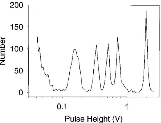
Because the molds can be reused indefinitely, this manufacturing method allows economical mass production of the devices. The depth of focus of the microscope was controlled by centering a 1 mm fluorescent bead in the laser beam. Individual DNA molecules gave measurable pulses, the height of which corresponded to the length of the molecule.
For the longest molecules in the lambda ladder (Fig. 6.4), the SMS resolution begins to degrade due to the optical setup: the molecules become larger (or longer) than the region illuminated by the laser beam used to detect fluorescence on to wake up In both graphs, the error bars are smaller than the size of the data point symbols.
Appendix A
Most catalog numbers are from the Digi-key, Theif River Falls, MN 100 k sample/sec 16-bit Quad A/D converter parts list. Most catalog numbers are from the Digi-key, Theif River Falls, MN Quad 1 Mhz A/D Converter Board Parts List. The item numbers in the above parts lists do not match the numbers in the chart.
Non-numbered items above may be needed for alternate configurations Most catalog numbers are from Digi-key, Theif River Falls, MN. Most of the catalog numbers are from digi-key, Theif River Falls, MN Quad photodiode transimpedance amplifier parts list. 15V and +10V regulator for quad photodiode power and +5V regulator for DSP and ADAT board power scheme.
Finally, on the right is the +5 V regulator for the DSP and ADAT cards.