Gavalas ken ti nagturpos nga estudiantena a ni Be Lai gapu iti tulong ni Ill£' iti BET llleaSUJ'('nH'llts .orage capacitives of.
List of Tables
Chapter 1 Introduction
- Hydrogen
- General Aspects
- Production of Hydrogen
- Storage Methods
Natural gas is exposed to st. 1 ('ll)H'rature ('all to produce hydrogen, carbon monoxide and carbon dioxide II. New mdal havp 1lf'PIl alloys developed that offer better hydrogel st.orage characteristics of llletal single hydrides .
Pressure [MPa]
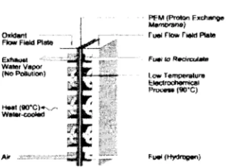
Fuel Cells
- Fuel Cell Principles
- Fuel Choice for Fuel Cell Vehicles
The operating temperature of tile pollyller elect.rolyte lll<'lllhralle fuel cells is limited by the area in which water is liquid, as the previous water is ('sellt.ial for conductivity' Eight major car manufacturers have set a framework for the commercialization of all vehicles.
Carbon Materials
- Graphite and Graphite Materials
- Activated Carbon
- Fullerelles
- Nanotubes
- Graphite Nanofibers
This is the needle applied to carbonaceous products derived from the pyrolysis of PVJ)(' or Saran resins. In the solid substance, t.lw CliO structure is facf'-cf'nt.erf. 'c1-cubic (fcc ), as shown in Figure log.
![Figure 1.4: Proposed model of tlw tangled st.ructure of vitreous carholl [10]](https://thumb-ap.123doks.com/thumbv2/123dok/10399766.0/29.810.283.542.428.610/figure-proposed-model-tlw-tangled-ructure-vitreous-carholl.webp)
Physisorption and Chemisorption
- Languluir IsotherUl
- BET Isothernl
On the other hand, when copper or iron is lllixecl with llickf'L, there is a significant increase in the ill(' wetting characteristics with resp('ct to graphite and such catalyst particles that can gClwr carholl llaIlO.S of higher order it is possible to control the llorphology of the hi nalophil. In general, the nanofi structure consists of an inll('J' core of allorphous carhol StllTOllllc\f'd with a graphite platelet skin It is also clear that the international structural arrangement of call it distinctly different from that described above, everything is extremely sensitive to a number of factors, especially the dwmic nature of the catalyst of all tlw composition of the gaseous reactant.
This small enthaJpy change is insufficient to cause the bond to break, so a physisorb('d) molecule retains its inability, altho1\gh it may 1)('distorted by tllf' i)!'ps('nce of the surface. (' nthalp~' of chemisorption is VNy 1lluch greater than that for physisorption, and typical valuesJ are in the region of 200 kJ / lllol [S ']. valences of surface atoms. t.he gelH'ral adsorber t .erm for ti]P material in the gas phase which is capable of absorption.
By equating the rate of evaporation of gas Illolccu I('s to all adsorbed layers with the rate of evaporation from this later and Slll1l1l1illg for all an infinite number of layers.
Bibliography
Chapter 2 Experimental Techniques, Equipment, and Data Analysis
- Sample Preparation and Modification
- Nanofiber Synthesis
- Kditscluuer-Huffulan Method - Synthesis of Fullerenes
- Single-Walled Nanotubes Production
- Sonication and Filtration
- Catalyst hllpregnation
- Sample Characterization
- X-ray Diffraction
- ray Line Broadening
- Translllission Electron Microscopy
- Fourier Transfornl Infrared Spectroscopy
- Sample Measurement and Data Analysis
A water separator is required to prevent all accidental(,lIt,all~' from being sucked through the vacuum line. Changing a preparatory variable can affect the structure of the calalyst and its characteristics (metal surface, crystallite size, distribution and dispersion) directly related to the performance of the material, during the impregnation of the solution ion, the concentration of the solution, the Ilwtal COIll-.
The uptake of this solution depends on the porous structure of the support. It is believed that the ultrasonic treatment l)(' is negative for the rf' activity of solid catalysis due to the surface defects. This was to ensure that the particles would not remain in the pore system rather than migrate to the outer surface of the carrier.
In-line cold traps are located between the vacuum pump and the manifold in bot.h anaJysis and the degassing system.
![Figure 2.1: The configuration in the :2" system vvith about 1 g/day product.ion rate (from [8])](https://thumb-ap.123doks.com/thumbv2/123dok/10399766.0/54.808.223.650.88.277/figure-configuration-34-vvith-day-product-ion-rate.webp)
Chapter 3 Hydrogen Desorption and Adsorption Measurements on Graphite
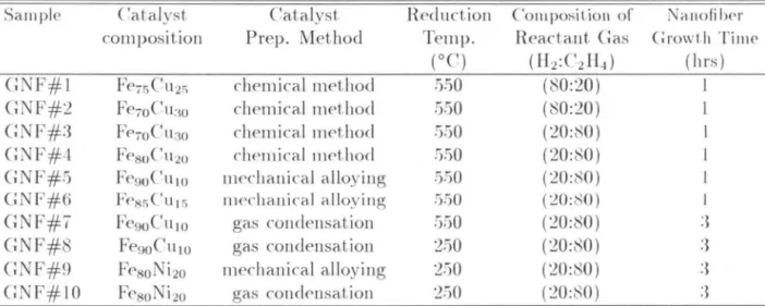
- Catalysts and Sample Preparation
- Sample Morphology
- Isotherm Measurement and Data Analysis
- Results
- Discussion
- Conclusions
Due to the potential importance of new materials with high hydrogen storage capacity for the global energy sector ('CONOIILY, transport systems and interplanetary propulsion systems'), we have assembled graphite structures from synthetic material. suitable morphology to make Ollr own llf'aSlllf'nts of hydrogen absorption and desorption. Before measurements of hydrogen adsorption and desorption, the samples were vacuum annealed at 900°('to''activate'' with nallofibers. The Sif'verts' apparatus was thoroughly checked for leaks at 200 bar and calibrated to provide a reliable determination of the hydrographic storage properties.
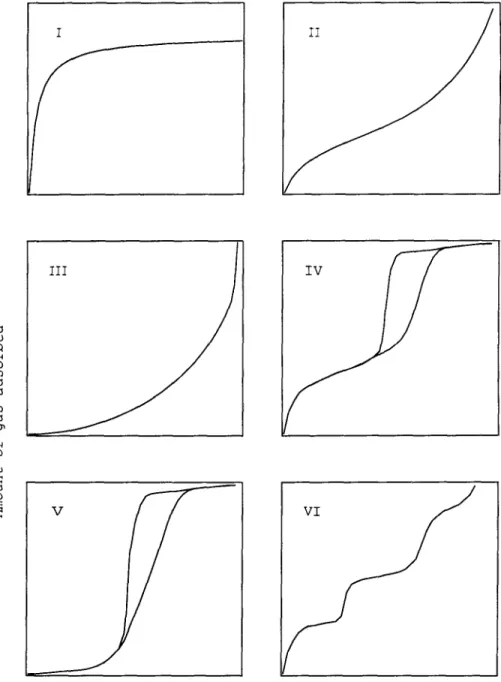
A lllacro program for the software package Igor by 'vVavemetrics was us ('d 1.0 calculates the quantitative mole number of hydrogen before and after each desorption step based on the pressure and the volume of the system. x) was assumed as the hydrogen replaced by the sample inside the reactor. For most samples we performed Illultiplf' runs at each daLa point to check the reproducibility of the results. At a given tempera(urp, the isotlWl"lllS for tllP graphite nanofibers and the saran carbon have a similar shape, but a vertical af[fse\).
None of the current hydrogen adsorption or desorption performed on any of the carbon nanomaterials showed a hydrogen storage capacity exceeding the values previously reported for various activated carbons [ 10 , 12 ].
Pressure [bar]
Chapter 4 Hydrogen Adsorption and
Cohesive Energy of Single-Walled Carbon Nanotubes
Background
Experiments
Isotherm Results and Cohesive Energy Calcu- lation
Surface area was measured with a Min:omeritics ASA P:2000 BET:,;is an instrument using nitrogen gas. The surface area of the S'vVNT material prepared as is, the material material after isotherm measurement, and the matfrary after solidification, will be 285±5 m2 jg. These results show the existing proportionality between the surface area measured by BET and the hydrogel adsorption, as did the hydrogen adsorptions at 160 bar at: 300 I\.
The low-pressure composite-pressure isotherms at 80°F and the high-pressure isotherms at 300°F had similar shapes for all carbon atoms. The chemical potential of a hydrogen molecule in the gas is Il, the adsorption energy is E (E < 0). At a low current, we found E =: 18 meV, which agrees very well with the results of Pace and Siebt'rt.
Figure 4.1 also shows the adsorption curve calculated from the saran carboll data with a decrease proportional to the lower surface area of the S\VNT material as measured by BET.
Saran I
SWNT
Saran x 3/16
Discussion
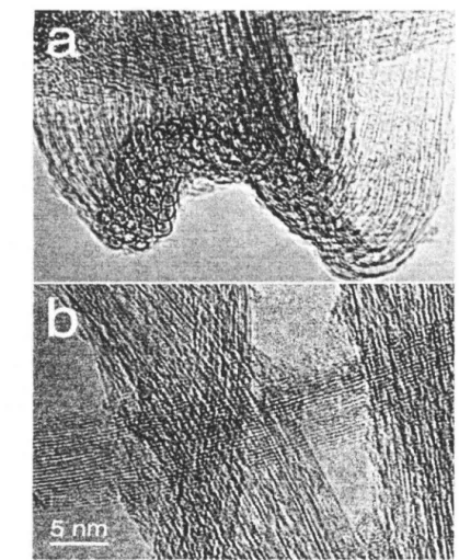
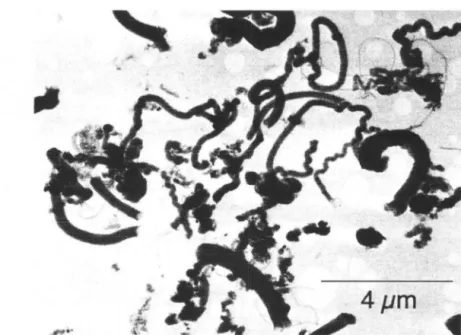
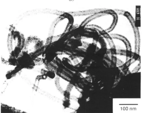
We can identify small red specimens with key features of TE1'vi morphology. With a 6-tube radius rope, the average number of the tube's first, nearest neighbors will be reduced from 6 to 0.5, so that the cohesion energy will be 5/6 of its value for a large crystal. This means that the reduced coordination at the rope surfaces reduces the cohesion energy by only about 15(/(,.
Figure 4.2 shows a significant curvature of the ropes, which typically yields maximum stresses in the tube walls of 0.5(7<1 or so). Since then there has been a rapid decrease with a distance of tIl('van der Waals interaction and other electron-electron correlation effects [f'spollsible for S'vVNT cohesion, anomalies in the close-packed triangular lattice of SWNTs would have a large reduction in the cohesive energy of S'vVNT It is expected that VNT crystals become smaller when intertube spacings are perturbed by tube ends, misalignments and dislocations within the crystalline rope.
The desorption pressures for this material show a considnahle width, indicating a distribution of the cohesive energies of the tubes.
Conclusion
Finally, we observe that the first-order phase transition causes SWNTs to adsorb and desorb within a narrower range of pressures, thereby overcoming an engineering challenge for hydrogen storage systems [22]. 24J We assume that the enthalpy of adsorption for a hydrogen molecule on curved S\tVNT is the same as on flat graphite.
Chapter 5 Hydrogen Adsorption and Phase Transitions in Fullerites
- Background
- Experiments
- X-Ray Diffraction Pattern and Phase Trans - formation of Fullerite
- Discussion
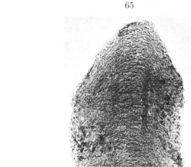
This value corresponds to complete Hz adsorption on the surfaces of the fullerene molecules. Samples of the samf' material were analyzed for their surface area by the BET method. The large particle in the left of the upper brightfield image is the rf cycle of a larger fuUcrite particle.
One energy is the adsorption energy of the Il2 molecule on the carbon surface. The second energy is the van del'waals energy of cohesion of (\lO and (',0 crystals. 34;energy") is the chemical potential of l1locules of hydrogen, which increases with ]HeSf.;ure of hydrogen gas.
It is possible to reduce this contribution to the total free energy by surface adsorption of some hydrogen.
Chapter 6 Carbon Supported Catalysts
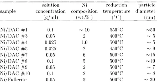
- Ni Catalyst Particle Size Control and Calcu- lation
- Nil Activated Carbon
- Ni/Fullerite
- Results and Analysis
- Isothenll Measureillent
- Isotherlll Results
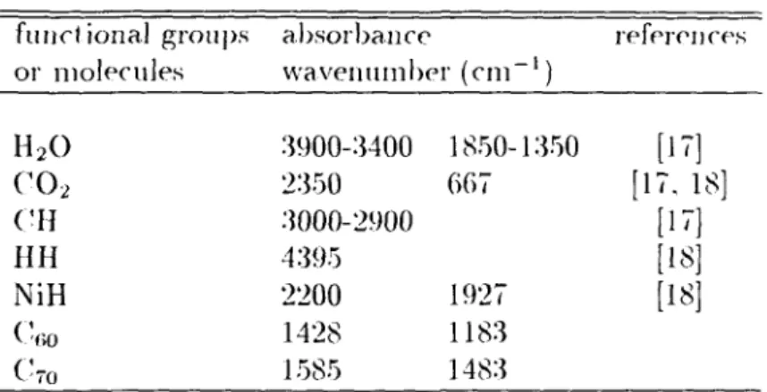
- Fourier Transfornl Infrared Spectronletry
- Conclusion
Usually yes. The improvement of the reactivity of solid catalysis resulted in the creation of surface defects, the reduction of particle size and the dispersion of catalyst particles on the support [7]. The particle size of the Ni catalyst was smaller after sonication, while all other preparation parameters were the same. The reactor was disconnected from the rest of the system and the system was again evacuated.
The reactor was shut down and the manifold's pr(,SSl1r(' was increased by introducing more hydrogen into the system. These steps were repeated and the pressures before and after the valve was opened were recorded until the pressure of the entire system was approximately 100 bar The desorption capacity v of the sample was lower than the adsorption capacity of the same sample at the same isothermal conditions.
From the thermodynamics of adsorption, the 'fractional coverage' of sllrfacc increases with decreasing temperature and increasing pressure.
Chapter 7 Conclusions and Outlook for Further Work
- Conclusions
- Further Work
From the change in the chemical gas adsorption potential of the IIpOll hydrogel, we were able to calculate the van der Waals cohesive energy between the tubes as atom 0.5 meV Ie. This is much smaller than expected from previous theoretical work and indicates that defects in the crystal structure cause large suppressions of the cohesive energy. We were able to change this cohesive energy depending on the state of the material.
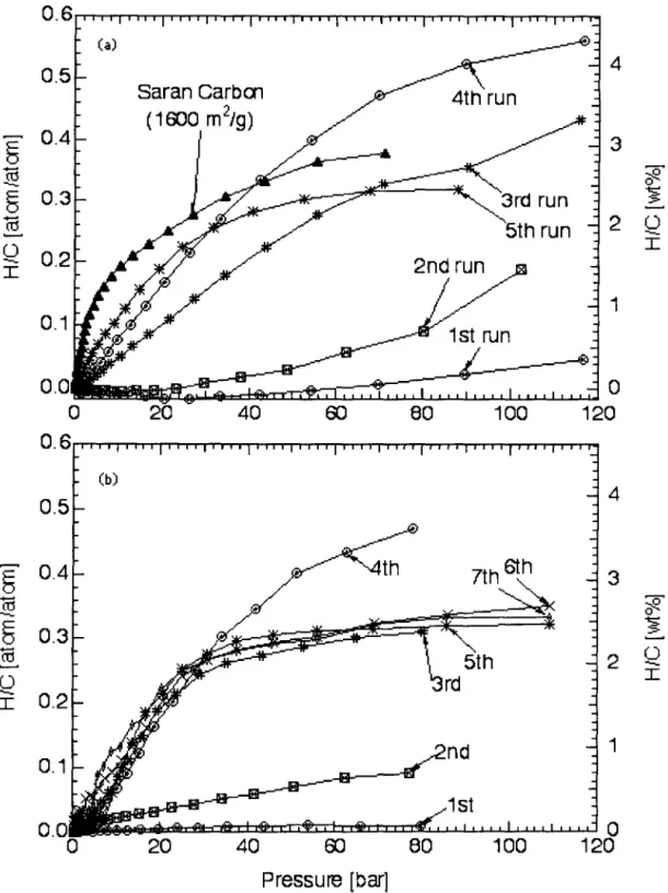
Over several cycles of isotherm measurements at 77 1\, the hydrogen storage capacities of one of the fullerite samples in (Tea~·wd from an initial value of 0.4 wt.% for the first cycle to a capacity of 4.2 wt.% for the fourth cycle Pure Cno and pure ('TO were run and exhibited small and constant capacities of 0.7 wt.% and 0.:3:3 wt.%, respectively. The relationship between the structure and properties of the mixed fullerite samples remains uncertain, however .
Further investigation will be required to identify the origin of the structural stability of fullerites such as fullerite #1.
![Figure 1.1: Compressed hydrogell dellsi t.y (data are ohtailwc\ frotH [1]).](https://thumb-ap.123doks.com/thumbv2/123dok/10399766.0/19.810.128.700.155.903/figure-1-compressed-hydrogell-dellsi-data-ohtailwc-froth.webp)
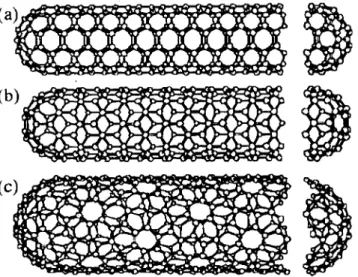
![Figure 1.8: The unrolled honcycomb lattice of a Ilanot.ulw (frolll [40]). \VIWll we](https://thumb-ap.123doks.com/thumbv2/123dok/10399766.0/37.814.171.630.532.848/figure-unrolled-honcycomb-lattice-ilanot-ulw-frolll-viwll.webp)
![Figure 3.6: Raw data of desorption steps at room U'lll]Wrat HrE'.](https://thumb-ap.123doks.com/thumbv2/123dok/10399766.0/81.808.109.681.146.499/figure-raw-data-desorption-steps-room-wrat-hre.webp)
