The invention and development of the radiosonde : with a catalog of upper-atmospheric remote sensing probes in the National Museum of American History, Smithsonian Institution / John L. Furthermore, the chronological part of the history of the radiosonde which is the focus of this monograph (1929 to 1940) is particularly important because it was during these years that the basic design features of radiosondes developed, and because these developments laid the foundations for the introduction in the 1940s of multichannel radio transmission via subcarrier modulation (the basis of all modern analogue radio telemetry systems). The reason for this publication is the presence of a significant collection of significant examples of the radiosonde in the National Museum of American History (NMAH), Smithsonian Institution.
The following sections outline the historical development of the radiosonde from its invention to the present. Finally, there is a catalog of the radiosondes in the collection of the National Museum of American History, Smithsonian Institution.
WmL> 1 pffa
Preradio Telemetering, 1842-1894
The development of the electromagnetic telegraph progressed rapidly after about 1830, and by 1840 many miles of circuit had been built. Various schemes for representing alphabets and numbers were available, such as the Morse-Vail code, but these were only translations of the original symbols. The small difference in natural period had no effect on the mean period of the receiving pendulum because synchronization was re-established each cycle.
In contrast, the accuracy of analog data is closely related to the parameters of the transmission system. The transmission was 'digital' and thus accuracy was independent of the uniformity of drum rotational speed (although this was limited by the number of conductive rods incorporated into the drum).

Radio Telemetry, 1895-1929
When Marconi applied similar tuning to the antenna circuit of a receiver, the overall effect was dramatic. From a Marconi Instrument Company promotional brochure sent to the electronics industry in the spring of 1987). One side of this widely tuned circuit was connected to the dragon's steel tether.
Idrac significantly improved reception by using a parallel tuned circuit inductively coupled to the ground cable. This circuit, a plate-tuned triode oscillator with inductively coupled feedback to the power grid, was used in the first regenerative receivers (Figure 17).
RADIO APPARATUS
This circuit, which is largely unchanged, and a Hartley circuit in which the grid is tapped by the plate coil, later became standard radiosonde transmitters.
Amateur and Experimental Use
Radio foi* Corporation
The Early Years, 1921-1928
He had noticed that the characteristics of radio transmitters changed due to the effects of temperature and other meteorological conditions. The secondary of the transformer stepped up the primary voltage to provide approximately 200 volts to the tube plate. The oscillator's plate coil was located in the center of the antenna, which formed a centrally fed dipole with a total length of 25 meters.
Indeed, the radiosonde was described earlier in this publication as a "natural" extension of the balloon probe. By the end of the nineteenth century, improvements in the design of kites and balloons made it possible to obtain above-altitude data on a more regular basis. In the first decades of the twentieth century, improvements in weather science were partly attributable to advances in theory and partly to the increasingly intensive exploration of the upper atmosphere.
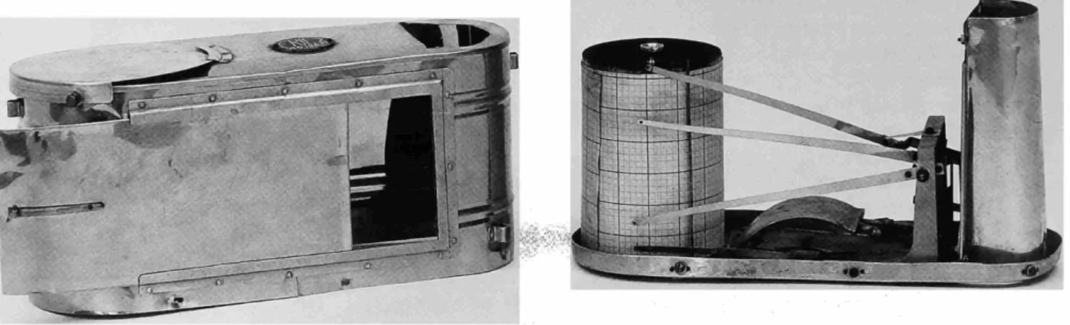
From left to right, the windmill and gear for modulation, the semi-metallic, semi-insulating cylinder, the gear wheel that holds the ignition locking chamber (i.e., the metal shaft parallel to the cylinder), the thermometer arm, and itself bimetallic thermometer. Changes in the electrical characteristics of such components as the atmospheric parameter being measured changes, in turn, changes the radio signal, usually through a change in frequency. The missing tenth tooth on the steering wheel produced a gap in the small frequency modulations that signaled a full cylinder turn.
The thermometer arm is at the bottom of the cylinder, and the barometer arm is at the top. According to Beelitz Moltchanoff also stated that this flight "was the first in the world where a radiosonde was used for the exploration of the atmosphere". This. Pressure was measured by means of a Bourdon tube and indicated by signal breaks.

Maturity, 1931-1940
QfrO^QfrOg-
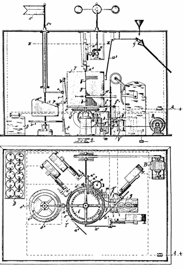
On the ground, signals were picked up by a conventional receiver coupled to a rotating cylinder type facsimile recorder. The hair hygrometer moved an arm that, along with a fixed contact, shut down the transmitter once for each revolution for a period of time indicating the humidity. Contact arms from a bimetallic thermometer, aneroid barometer, and hair hygrometer touched conductive parts of the rotating cylinder in a manner that produced combinations of two Morse code for each sensor.
The Duckert radiosonde underwent several modifications in the 1930s (Duckert including replacing the oil-filled variable condenser used as a temperature sensor with an "electric" thermometer consisting of a temperature-sensitive capacitor. The redesigned designs of the Duckert probe were introduced in mass-produced in the 1930s by the German company Telefunken. Since the natural frequency of the spring was 1500 vibrations per minute, the shaft of the motor rotated with great constancy at 1500 revolutions per minute, thus reducing this source of inaccuracy.
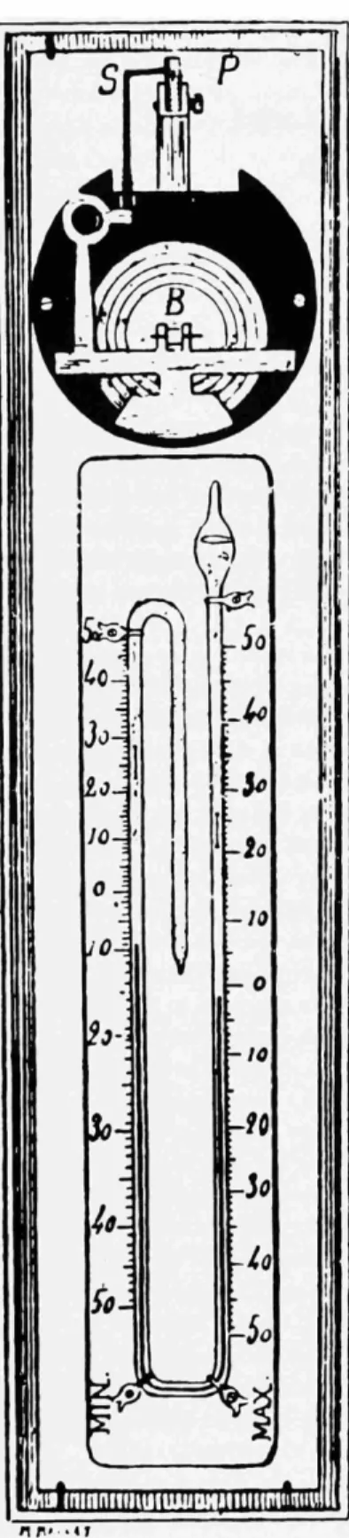
The probe frame was isolated from the rotating spiral contact and supported an aneroid barometer (E), a bimetallic thermometer (F), and the goldbeater skin hygrometer (G). The contact arms of each sensor moved along a spiral, so that the end of the spiral touched the reference points H and J once per revolution. Because each of the three sensors required a separate oscillator, it was heavy, a defect magnified by the fact that the "read" method.
Two of the capacitances were of fixed type and were used as references, and the remaining three were variable according to the sensor output (see Figure 44). During each cycle of the switch, two reference capacitors were connected to an oscillator circuit as a means of eliminating errors caused by frequency drift. Note the symmetrical half-wave antenna required the probe to be centered between each half of the antenna.

SCALE
The Radiosonde after 1940
Research from the previous period has also demonstrated the utility of the radiosonde for a variety of geophysical applications, which are discussed in this section. This method was similar to that used in the Duckert probe described in the previous section. In the United States, the NBS-Navy probe was taken over by the Weather Bureau, but in the early 1940s the US was taken over.
At 1680 MHz, the antenna was small enough to be independent in the radiosonde package. In the late 1950s and 1960s, additional models appeared with changes in mechanical construction, such as the AN/. In the early 1940s, another factor, interference, began to affect the operating frequency of radiosondes.
The evolution of the radiosonde with frequency modulation for audio subcarriers was important for the development of data telemetry. In the 1940s, the introduction of multi-channel radio telemetry enabled the simultaneous transmission of the output of numerous sensors. Also, the development of multichannel radio telemetry was accelerated in the immediate postwar years by the needs of military missile programs.
At that time, the question of whether "primary" cosmic rays (i.e., the component of such radiation that exists outside the Earth's atmosphere) were electromagnetic waves or charged particles was still unresolved. Johnson's probe (as discussed in the previous section) was designed to measure cosmic rays. In the late 1930s, Jean Piccard conducted additional research on cellophane balloons at the University of Minnesota.

Conclusion
Identified by the donor as a Vaisala type, improved by Schulze at the "Naval Observatory" in Griefswald (Germany) in 1942-1944. This white corrugated paper box, 28x 12x16 cm, contains elements for measuring temperature (two mercury thermometers and one bimetallic), pressure (aneroid) and humidity (hair hygrometer). The design above is a housing containing sensing elements for measuring pressure (aneroids) and humidity (gold beater skin) - the temperature element is missing (but see cat. no. 319830).
This paper-covered corrugated box, 13x16x12 cm, contains a transmitter, a barometric switch and sensing elements for measuring temperature (thermistor) and pressure (aneroid). Early investigators were aware of the potential advantages of shorter wavelengths, but they faced significant technological barriers to the use of shorter wavelengths. The first production models of the NBS radiosonde were standardized on the 4-meter range because this wavelength was low enough to achieve almost all possible advantages in smaller size and weight.
However, it did not place the radiosonde signals in an appropriate part of the radio band to solve all the problems. The displacement of the radio spectrum by overlapping transmitter frequencies had begun during the rapid expansion of radiotelegraphy before World War I, and the problem was serious enough to warrant the formation of regular international conferences to establish cooperative allocations of frequency bands before World War I . international use. Because these problems seemed unsolvable within the limitations of the mechanical approach, research into electrical sensors had begun.
In 1952, the Mk2B was introduced, featuring improved RF temperature compensation and the transmitter's audio subcarrier oscillator phases. Apparently, the accuracy figures for the European models were similar to those of the NBS-Navy type (ie, temperature within a degree in the range from plus 40 to minus 75 degrees Celsius; pressure within a millibar from 150 to 1050 millibar; and humidity within three percent from 0 to 100 percent relative humidity). There is little published data on the in-flight accuracy of production versions of various radiosonde designs.