Windscreen and bayonet imaging system mounted below the model in the tunnel and acts as a main support image '\.Jind- shields and bayonets. It is clear that the accuracy of the tare value will be the same.
Specific attention must be given to all parts of the imaging system on which the air forces directly add to the weeds. The probable origin of the onsymometry is: a poorly loaded wind tunnel fan, a small·contraction ratio, a short.
This increase in the slope of the lift curve is considered to be equivalent to the effective increase in velocity due to the blocking effect of the imaging system. 3 the lift, drag and pitching moment curves (versus CL) for all four runs of the tare range are presented.
In general, it is best to keep the model state fixed for all four runs in the tare series. The tare runs should always be performed consecutively and only by experienced members of the operating staff.
PART II
A serious attempt is made to provide a clear picture of the complex flow patterns in the tunnel, with both the windshields and the model present. The large conning tower in the throat ceiling has been shown to significantly alter the normal blocking.
PFH Er.t 451"
Introduction
Even with these precautions, it was soon discovered that there was an unusual amount of scatter in the balance readings, particu-•. These difficulties were largely eliminated by sharpening the edges and blades of the balance knife, recalibrating the balances and rearranging the suspension system.
Coupled with these effects, large deviations in the angle between the direction of the streamlines and the tunnel axis must occur. It is assumed that the flOi{ direction does not change with the addition of the Hindshields. Note that lifting and dragging the tailskid seals and bayonets will cause a tare moment.
It is an example of a uniform slope (only in the vertical direction) of the flow lines with respect to the axis of the tunnel. Estimates of the tare characteristics for this case are given by the Qy curves in the figure. The experimental results discussed in the next section are part of the work planned for the first phase.
Comparison of the results of Runs 34 and 36 shows that the opening in the floor (plus the s~ll deflector) for the image tail outer shield has a negligible effect on the q at the wingtip position.
The variation of tip pressure with yaw angle is interesting but not particularly significant, although the bayonet causes noticeable changes in local pressures. Comparison of runs 10 and 29 shows the effect of the image wing shield, F~, when mounted below the main ldng shield ldng on the tip pressure at. Note that the rear tail shield is moving along the centerline of the throat, ~ while the wing shield is offset about 16 inches from this centerline.
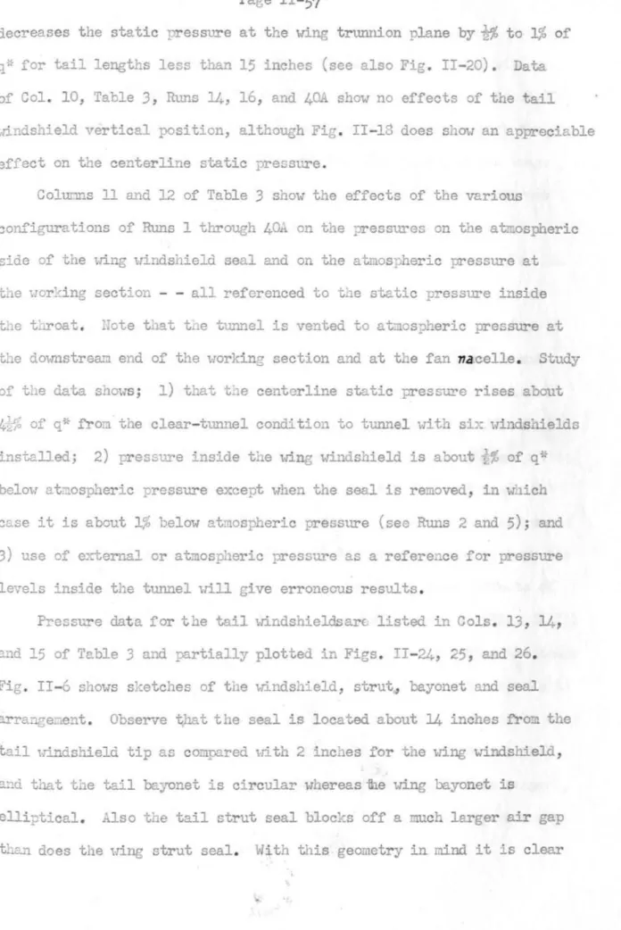
The effects on the pressure at the tip of the image tail shield and the access hole in the tunnel floor (deflector) are less than 1% of q* - - see runs 34, 36 and 40A in Fig. This has a noticeable effect on the static pressure on the centerline. Configurations from Runs 1 through 40A on the pressure on the atmospheric side of the wing shield seal and on the atmospheric pressure in the llor: Due to the large air gap between the tail strut and its end shield, there is significant airflow through the windshield into the tunnel, and the peak pressure rises to within 10% to 15% of atmospheric pressure. This data gives the balance readings for all the runs made outside a model in the tunnel, and represents the resultant of the direct air loads on the entire support system. 34;, as caused by roughness on the knife ecl€es and pallets of the beam bal.nsions and, when angle of ya'{ or pitch is varied, Oy deflections in the suspension system. Here we define a precision value as largest allowable deviation from the true reading for all normal flight attitudes of the model below CL = 1.0. When a model is attached to the bayonets, part of the bayonet is covered by the model and thus not exposed to the crustal flow. This indicates that the tail strut seal should be mounted as close as possible to the tip of the tail strut tail shield in a manner consistent with the arrangement of the strut seal used. Inspection of the results for all other runs shows significant lift measurements even though there is no model in the tunnel or any other type of "lifting surface" (see Figures II-5, 6). Inspection of the physical dimensions of the seals (see Figs. 11-5, 6) shows that the calculated effective diameter is close to the actual diameter of the seals. To the lifting tares (dwithout model) discussed in section (c) of group 3, the influence of the node on the \nndshield must be added. Hoilnage bayonets have been installed, and no corrections have been made to block the pictorial windshields. 11-39 shows the effects of the vertical position of the windshield of one image placed in the middle of the tunnel. Note that Cm and O This was adjusted in Run 130 by deflecting the aileron trailing edges at the corner upstream of the throat until the wing roll monent was negligible. The 0.0006 difference in resistance seems far too large to have a model interference effect on the bayonet resistance, and thus must be explained by bayonet interference on the model or (more specifically) by poor balance data for the model tests. It is believed that windshield interference on the model's drag at zero lift is negligible, although conclusive evidence is lacking. Since only two of the usual four runs were made, it was not possible to correct for irregularities in the free tunnel, flm!, resulting in taring for pitch. Pitching moment, lift, and drag curves are quite similar to those for no swing angle. The results are very similar to those for the 58" spacing discussed in the preceding paragraph. However, there is a large difference in effective dnd current slope for the tHO tunion spacing - - 0.330 dOllmlash for the 58"- spacing and 0.180 for the other - - which may be an indication of the reason for large differences in the rolling moment data. It is likely to be expected that the effective lift produced by qy image shields will decrease as they move toward. It was assumed that this 0( g shift was in fact an error in CLg and the drag data for Run 97A was corrected accordingly before the stall resistance was determined. As the wing yaws, a stall will approach and with a sufficiently large yaw angle come in the wake of the second plug, thereby producing ~n interaction between the two so that the effects of both plugs combined will not equal twice the effects of one plug.the most important thing. The "lift area" of the stinger is about 2% of the surface area, but "with such an extremely high aspect ratio it is hard to believe that the stinger could develop that much lift, and furthermore the stinger lift would have to be the largest. " same at ljI = 00, which was not the case at all. The author believes that the stitches act as double flaps of small cords or small stable plates that build up the pressure on the pressure side more than on the suction side and there an effective lift - - even in this case it seems that the effect should increase with the yaw angle. In any case, it was decided that this 2.6% lift increase was a real stab arra. 6fo has been measured and the drag tare is assumed to be constant at 0.0006 for all angles of attack. Furthermore, applying the wall correction for pitching moment will reduce this experimental value to 23.1%. It is quite possible that applying the corrections for bayonet and strut seal lift will account for these differences. This shows that the law for uplift is only as good as the accuracy of the experimental results. However, it should be noted that CCS reverses the sign of the deflection angle. The yaldng moment agrees with theory in that it is a linear function of the deflection angle. It appears that the theory agrees with the experimental results within the accuracy of the measurements. Smith, J.E., "Report on the GALCIT Method for Determining the Aerodynamic Interference Effects of the J·lodel Suspension Systen", CALCIT Rep. I ~OCI Assume that the pressure outside the tunnel is equal to the static pressure of the free stream. For a long, conical strut of circular cross-section, this average pressure may be assumed to exist at all parts of the strut except the bottom, which is exposed. Obviously, the lift tare will be the least when the strut seal is at the tip of the windshield. To obtain the average pressure, the perimeter length of the airfoil must be determined. Some time after the completion of the tests described in Part II, Section I, Group 1, an opportunity arose to determine the blocking of the various windshields with the control tower closed (roof fairings inward and deflector outwards). Unfortunately, there was no time to determine the incremental effect. however, these data are sufficient to justify the belief that with the open conical tower, the pictorial windshields do not duplicate the blocking effect of the main windshields. 10 we determine the change with wing lift of the pressure at the top of the wing glass, we will add the increase in velocity due to the wing to that at the tip without and then calculate the pressure.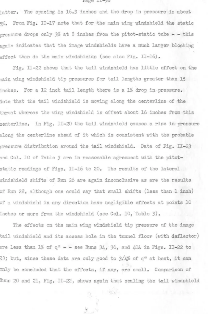
Page II- 59
Page II- 66
IWP{