INTRODUCTION
OBJECTIVES
Some Elements Of The System
For the present discussion, focused on (preliminary) network design, it is assumed that the design flows to be delivered to the tertiary blocks and the sizes of the tertiary blocks are known. The number of days per week that these supplies will be delivered is, of course, a function of the irrigation requirements at the various stages of crop growth.
The Irrigation Network
- The Irrigation Blocks
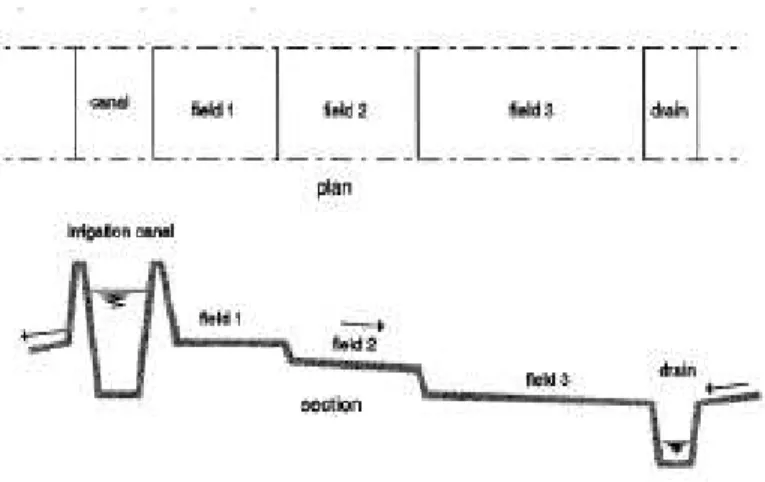
- The Fields
- The Tertiary Units
- The Secondary Units
- The Command Area
The size of the village areas influences the internal organization of the farmers in the block. The road network may be public or even part of the general road network of the area.
The Preliminary Layout Of An Irrigation System
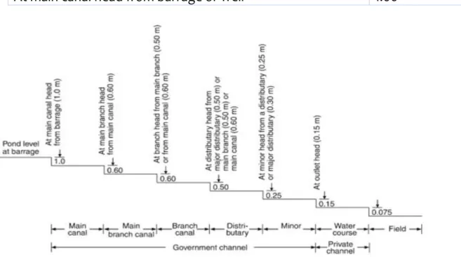
- Determination Of Full Supply Level (FSL)
- Working Head
- The Horizontal Alignment Of Canals
- The Vertical Alignment Of Canals
- Water Levels In The Major Supply Canals
- Areas Served By The Canals
- Design flows in the main system
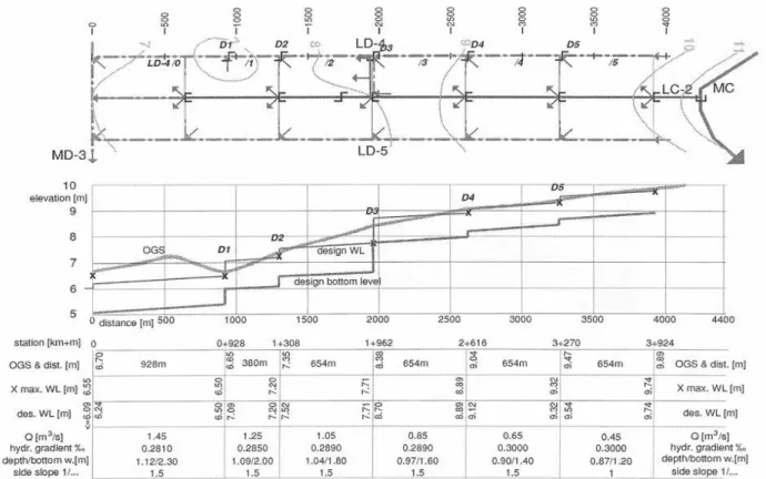
Ground surface elevations are obtained from the map or a survey along the proposed alignment of the canal. Encroachment on the freeboard of the canal would be permissible in such a case (and only in such a case).
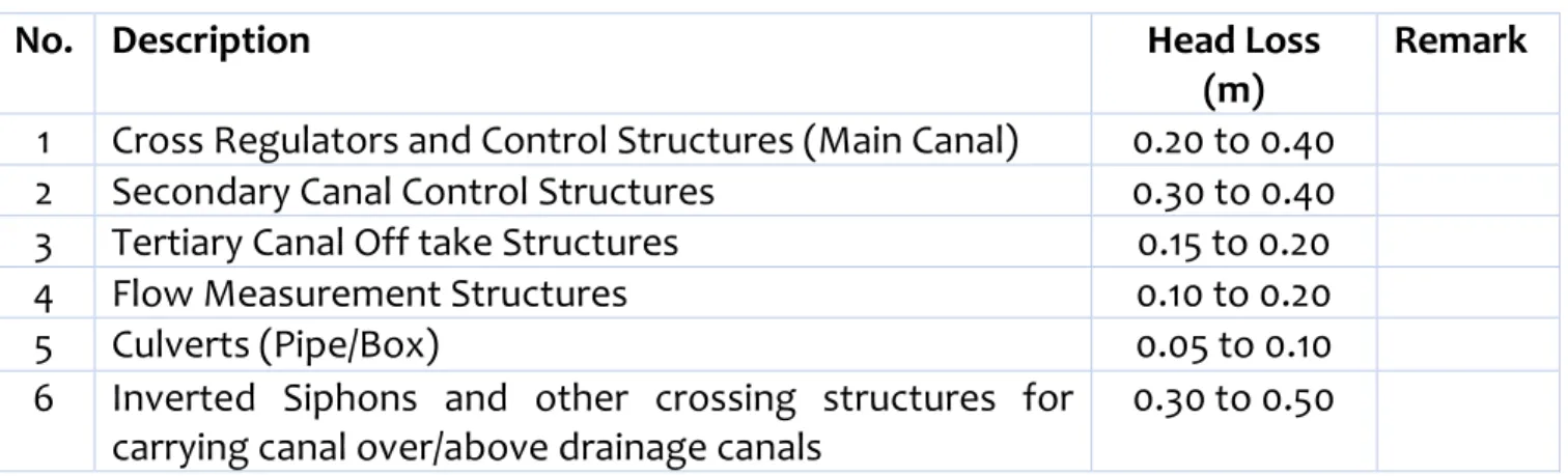
Introduction to Structures in Irrigation Canals
- Structures For Crossings
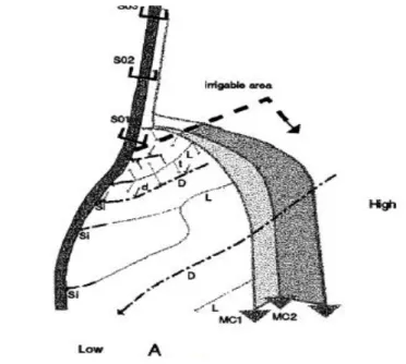
Larger flows than planned would have to be diverted to a specific area when, for example, rapid flooding of all blocks is necessary to control rats. The design flows in the main and side canals can be reduced if an area of more than about 300-400 ha is served from such a canal. It has been observed that in such a vast irrigated area all the land will never be under cultivation at any one time. This would result in lower water demand with continuous irrigation and theoretically shorter water delivery periods with rotational irrigation. .
This potential reduction is difficult to take into account in the preliminary design phase. It is not economical to vary the design flows downstream of each outlet or each outlet. Such crossings are, for example, tunnels that cut through a hill or mountain to reach a certain part of the area or to reduce the length and fall of the canal, thereby increasing the irrigation area or reducing the pumps' heads.
It is also possible to temporarily impound the runoff on the high side of the canal or to let it enter the canal. However, the additional drain water flow should not exceed 10% of the design flow of the canal, as previously mentioned.
Structures For Water Level Regulation (Level Control Structures)
- Structures For Division Of Water (Flow Control Structures)
- Structures For The Distribution Of Water To The Fields
- Structures For Safety
Crossing existing watercourses (cross drainage structures) can be achieved by installing an inverted siphon under the watercourse, or the watercourse can be guided via an inverted siphon under the supply channel. The inlet structure can be of the on-off type or can also control the amount of passing flow. The general term 'water management work' can therefore refer to either type or to a specific type of structure.
Water control structures can be combined or supplemented with discharge measurement structures to determine or register flows at various points in the system. Emergency exits (wasteways) in supply channels in front of water level regulators or in places where the capacity of the downstream channel is limited. The inflow may be excessive due to operational errors or due to uncontrolled quantities.
Emergency exits upstream of high loading canals where any overtopping of the canal banks would be catastrophic. A channel lining, whether with compacted earth or any other less permeable material, may be classified as a safety structure if it will reduce seepage to prevent subsoil sliding.
CLASSIFICATION AND ALIGNMENT OF CANALS
Classification of canals
Productive channels are those that are established with an idea to recover all the expenses incurred during the construction within a specified time limit. After full development of the canal system, the income derived from the operations is such that it is more than the maintenance expenses. This larger amount of revenue is adjusted to be about 2 percent of the cost of the canal system.
At this rate, the total cost of the project will be recouped in about 50 years. The construction of this type of canal and its development can begin in times of famine. With the advancement in irrigation technology and to meet multi-purpose needs, canals are constructed to perform various functions.
Like connecting canals, these canals may or may not provide direct irrigation along their course. A tail canal that directs water away from the power station can empty into the river or other canal system for later use.
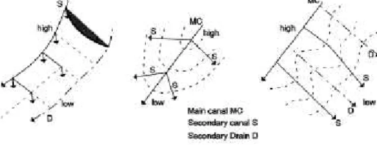
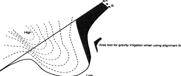
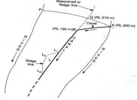
Alignment of canals
The catchment area in this case is the line that divides the area into two small sub-catchments. This alignment avoids cross drainage works as no natural drainage can flow through the catchment area.
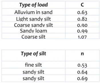
Canal losses
Seepage loss; the loss due to seepage is the most significant in terms of the loss of irrigation water from canals. When the subsurface water table is at a significant depth, the water that has penetrated the soil cannot join the saturated zone and the subsoil locally wets directly beneath the channel bottom. The soil layer that is in direct contact with the channel section is completely saturated by absorbed water.
The degree of saturation therefore decreases with depth from the ground level below the ground. So there is no chance of continuous and constant flow from the canal to the groundwater reservoir. In such conditions, water flows directly from the channel to the underground reservoir through the soil pores.
The pressure responsible for this flow is the difference in level between the groundwater level and the water level in the canal. Measurement of seepage loss: Seepage loss is generally measured with a very simple method, the so-called inflow and outflow method.
DESIGN OF IRRIGATION CANALS
Design Criteria For Irrigation Canals
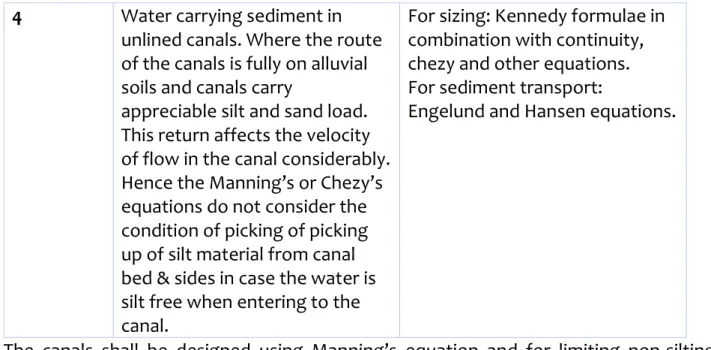
Channel design depends on the need to prevent erosion, which depends on the base material of the channel. 2 Water carrying sediment in lined channels.. governed by the need to provide a transportable sediment load. Both don't-. scouring and non-filling criteria, while "ridge" channels are subject to non-filling criteria because they generally run downslope. a) Steep terrain - traction force method;.
Therefore, Manning's or Chezy's equations do not take into account the condition of collection of silt material from the channel bed and sides if the water is silt-free when it enters the channel. The channels shall be constructed using Manning's equation and to limit non-sludging, non-scrubbing velocities, the channel sections shall be controlled by Kennedy, Lacey's and traction equations as appropriate. Design the various sections using Manning's formula and also check the CVR, especially in the main channel where the water may be silted.
Check the longitudinal slope of the channel and the flow velocity according to Lacey's theory where the water is loaded with silt; and. Determine the CBL (Channel Bottom Level), TBL (Top Bank Level) to achieve the required full supply using the channel design parameters.
Design of unlined canals
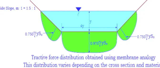
- Method Of Tractive Force
By definition, drag is the force acting on the particles that make up the perimeter of the channel and is the result of the flow of water past those particles. The maximum net drag on the sides and bottom of various channels as determined by mathematical studies is shown as a function of the ratio of bottom width to flow depth. A particle on the planar bottom of a channel is subjected to the unit drag force on a planar surface and effective area.
This force, which is nothing but the resistance of the water in the wetted area, is known as the drag force. A particle on the inclined side of the channel is subject to a drag force and a downward gravitational component. The drag force is equal to the component of the gravitational force acting on the body of water parallel to the channel bed.
Determine the maximum shear stress fraction (dimensionless, Kbed, for the channel bed, based on the b/h ratio and Fig. 6. Determine the maximum shear stress fraction (dimensionless, Kside, for the channel bed, based on the b/h ratio) and Fig. 7. Below Figure also shows places where maximum traction was measured on the side slopes, Kside, and the bed, Kbed.
For a very wide channel, the sides of the channel can be neglected and the critical tensile force on the channel bed can be taken as.
Design of lined canals
- Design procedure for lined canal
- Best Hydraulic Cross-Section
The best hydraulic (the most efficient) diameter for a given Q, n and S0 is the one with minimum excavation and minimum liner diameter. The minimum cross-sectional area and the minimum liner area will reduce construction expenses and therefore that cross-section is the most economically efficient one. The best hydraulic diameter for a given A, n and S0 is the diameter that transmits maximum discharge.
The cross-section with the smallest wetted perimeter is the best hydraulic cross-section among the cross-sections with the same area, as lining and maintenance costs will be significantly reduced. As can be seen from the equation, the wetted perimeter is a function of the side slope m and the water depth y of the cross section. For a given side slope m, what will the water depth y be for the best hydraulic trapezoidal cross section.
Design the most effective cross-section of a lined trapezoidal duct to carry a discharge of 15 m3/s when the maximum allowable velocity is 2 m/s. Secondly, sharp corners in cross-section are practically stagnant and can lead to the deposition of silt.
Canals on non-alluvial soils
Canals on alluvial soils
- Kennedy's theory
- Lacey's theory
These eddies are formed due to the friction of the flowing water with the channel surface. When the assumed value of D is correct, the value of V in step (6) will be the same as V calculated in step (2), if not assume another suitable value of D and repeat the procedure until both velocity values come out to be the same. It is clear that the vertical components of the forces due to eddies are responsible for keeping the silt in suspension.
Consequently, the amount of silt transported is not only dependent on the base width of the channel. Both theories agree that the silt is carried by the vertical eddies generated by the friction of the flowing water against the channel surface. For this reason, Kennedy's critical velocity formula was derived only in terms of the depth of flow (y).
On the other hand, Lacey considered that an irrigation channel acquires a cup-shaped section (semi-ellipse) and that the entire wetted perimeter (p) of the channel contributes to the generation of silt-supporting eddies. Lacey related wetted perimeter (P) as well as area (A) of the channel to discharge, thus establishing a fixed relationship between bed width and depth.