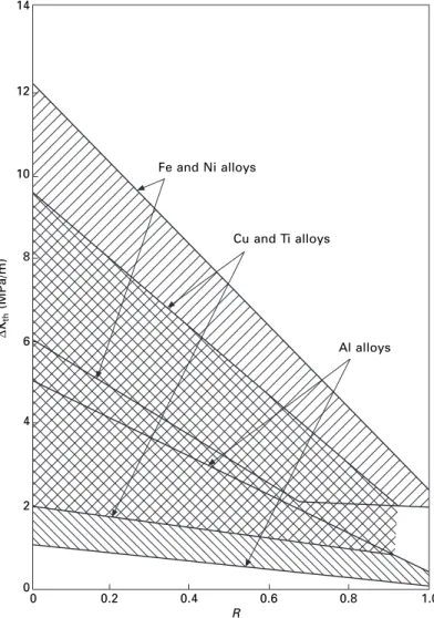
Woodhead Publishing Limited and Maney Publishing Limited on behalf of The Institute of Materials, Minerals & Mining. It is possible to present a broad 'overview' of the properties of engineering materials by constructing a material property diagram.
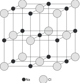
Crystal structure
Many of the physical properties of ionic crystals can be explained qualitatively in terms of the properties of ionic bonding. As the number of valence electrons and the density with which they are held to the nucleus increases, they become more localized in space, increasing the covalent nature of the bond.
Microstructure
Introduction to phase transformations
If a small sphere of solid matter (radius r) is formed, the free energy of the system will be lowered by an amount per volume unit corresponding to equation [1.3]. 1.5 (a) Drawing of a dendrite and (b) schematic representation of freezing of a liquid by nucleation and growth of dendrites.
Introduction to metallography
The most used is the electrolytic thinning of the material, so that it does not suffer mechanical damage. A guide to further reading in this highly specialized field is provided at the end of the chapter.
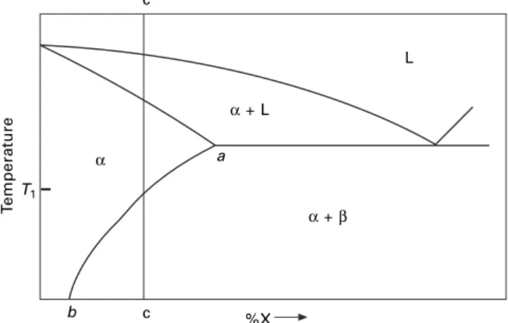
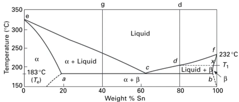
Some simple phase diagrams
The required compositions are given by the intersections of the isotherm with the phase boundary lines. An alloy of composition c will solidify at the eutectic temperature (183°C) to form a finely divided mixture of α and β crystals.
Molecular structure of organic polymers and glasses
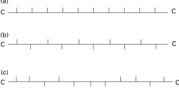
A number of shape memory alloys (SMAs) exist: the earliest devices were of Ni–Ti ('Nitinol'), but more recently Cu- and Fe-based SMAs have been developed in which an element 'remembers' the shape it has had before deformation. A syndiotactic linear polymer has the side group regularly alternating on either side of the chain (Fig. iii).
Further reading
Introduction
The tensile test
The behaviour of metals at larger strains
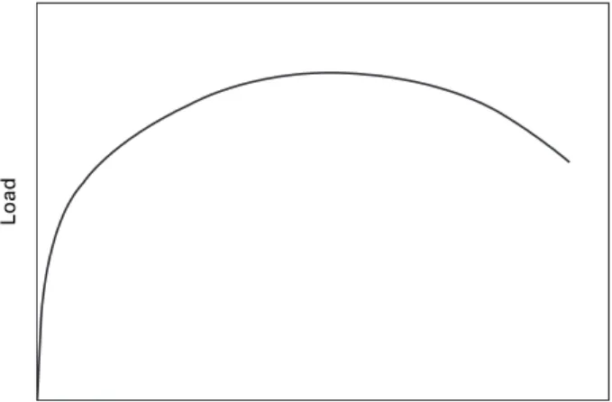
The volume of the sample remains constant during plastic deformation, so that its cross-sectional area gradually decreases as the gauge length increases. The rate of work hardening, however, decreases with strain, and eventually a point is reached where there is not a sufficient increase in strain from work hardening to compensate for the reduction in cross-section, so that all further plastic deformation will be concentrated in this region and the specimen will undergo necking as the strain gradually decreases. .
The engineering stress–strain curve
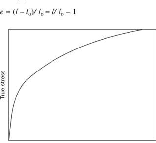
True stress–strain curve
If the true stress, based on the actual cross-section (A) of the gage length, is used, the stress-strain curve increases continuously to failure, as indicated in Fig. Equation [2.7] thus enables us to identify these values by means of the Considère construction, whereby a tangent to the true stress–.
Bend testing
In addition, the intersection of this tangent on the voltage axis will yield the value of the UTS, since . In three-point bending, the maximum tensile stress occurs at a point opposite the central load, and in four-point bending, the entire surface between the central loading edges, on the convex side of the bar, experiences the same maximum tensile stress.
Statistics of brittle fracture
Hardness testing
- Indentation hardness tests
- The Brinell test
- The Vickers test
- The Rockwell test
- The Knoop test
- The Shore scleroscope
The Brinell number (HB) is the ratio between the load and the contact surface area of the indentation. Either a steel ball (Scale B) or a diamond cone (Scale C) is used and the indenter is first loaded with a smaller load of 10 kg f, while the indicator for measuring the depth of the impression is set to zero.
Fracture toughness testing
The J integral
In a linear elastic material, J would be identical to G and the reader is referred to British Standard BS which describes methods for determining KIc, critical CTOD and critical J values of metallic materials.
Time-dependent mechanical properties
- Creep
- Superplasticity
- Fatigue
- Environment-assisted cracking
- Time-dependent elastic properties
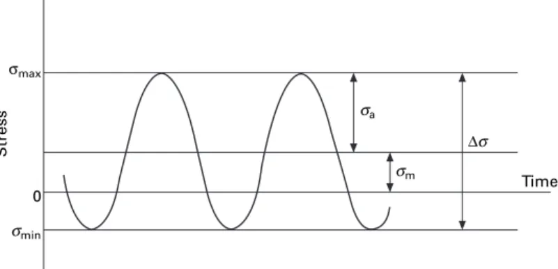
In these models, various combinations of the mean stress and stress range are plotted to give a constant (selected) fatigue life. This corresponds to Kmax in the fatigue cycle achieving the fracture toughness of the material, Kc.
General strengthening mechanisms: the effect of processing
- Work hardening
- Grain size strengthening
- Alloy hardening
- Strength at high temperature – creep-resistant alloys
- Resistance to fatigue failure
It is directly proportional to the initial grain size and the temperature of the previous cold work. The effect of pre-strain degree and annealing temperature on the final grain size formed after recrystallization is shown in Figure 1b.
The families of engineering alloys
Aluminium alloys
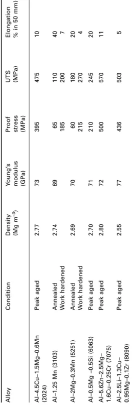
Aluminum-copper alloys, although less easy to cast than Al-Si alloys, respond well to age-hardening heat treatments. Aluminum-magnesium-silicon alloys (6xxx series) are medium-strength alloys widely used in the form of extruded sections for structural and architectural applications, window frames being a typical example.
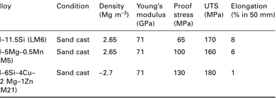
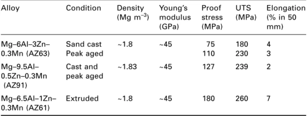
Magnesium alloys
An addition of copper is made to reduce susceptibility to stress corrosion cracking (SCC), and the Al-Zn-Mg-Cu alloys are widely used in aircraft structures. The most common plate alloy is Mg–3Al–1Zn–0.3Mn, which is strengthened by strain hardening.
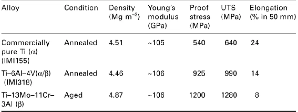
Titanium alloys
3.13, and are of paramount commercial importance, with Ti–6Al–4V accounting for more than half of world Ti alloy sales. Fine-grained Ti–6Al–4V sheet material is used in the aircraft engine industry for the superplastic molding of numerous components.
Copper alloys
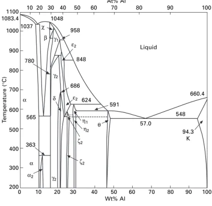
The structure of the copper-zinc alloys or brass can be understood from the phase diagrams of figure. Copper-rich aluminum alloys are known as aluminum bronze, the composition of the commercial alloys ranges from 5-11% Al, and the phase diagram of Fig.
Lead alloys
Zinc alloys
The casting alloys are based on the Zn-Al system (Fig. 3.19) and are close to the eutectic composition of 5% Al.
Nickel alloys
Nickel-chromium alloys form the basic alloys for the development of jet engines - the nickel-based superalloys, e.g. Even greater high temperature capability has been demonstrated on a research (rather than production) basis and is indicated by the top line of the diagram.
Steels
Additions of niobium or titanium can be made to 'tempt' the dissolved C and N atoms to form carbides or nitrides, improving the cold forming response as the steels are known to be interstitial-free ( IF). The diagram also shows that as strength increases, ductility decreases; this follows from the Considère construction (Fig. 2.6), since the stress for plastic instability (that is, the contact point of the tangent) decreases as the stress-strain curve increases.
Cast irons
These irons are so called because the presence of graphite in the microstructure leads to a gray colored fracture surface. Nodular or spheroidal graphite cast iron (SG) contains graphite spheroids in the cast state, with the addition of cerium and/or magnesium to the iron, as illustrated in Fig.
Joining of metals and alloys
- Mechanical fastening
- Soldering and brazing
- Welding
- Adhesive bonding
The area of the part adjacent to the weld is known as the Heat Affected Zone (HAZ). Adhesives are now also widely used in bonding the inner and outer panels of doors.
Degradation of metals and alloys
- Oxidation of metals and alloys
- Corrosion of metals and alloys in aqueous environments
- Stress, strain and corrosion
- Wear of metals and alloys
- Fretting corrosion and fretting fatigue
The bottom of the sample, which is farthest from the surface, is surrounded by liquid z. In the severe wear regime, the wear rate of the harder counterface is negligible, and the wear debris is metallic brass.
Further reading
If the surfaces are not intended to move, it may be possible to prevent slippage by increasing the friction between the surfaces. If the surfaces are intended to undergo relative motion, improving the lubrication should reduce the amount of intermetallic contact and thus improve the situation.
Glasses
- Soda lime glasses
- Borosilicate glasses
- Toughening of glass
- Self-cleaning glass
- Environment-assisted cracking
This approach made the implicit assumption that the surface temperature reaches its final value before there is any change in temperature in the bulk of the material – i.e. But σ* varies with time and we can write this in terms of the Biot modulus as
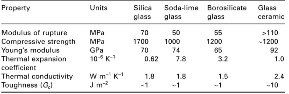
Glass ceramics
Essentially, water vapor at the crack tip can react with the molecules and break the Si-O bonds to form a hydroxide. When the crack has grown sufficiently for the critical stress intensity to be reached, failure occurs - the phenomenon is sometimes referred to as "static fatigue".
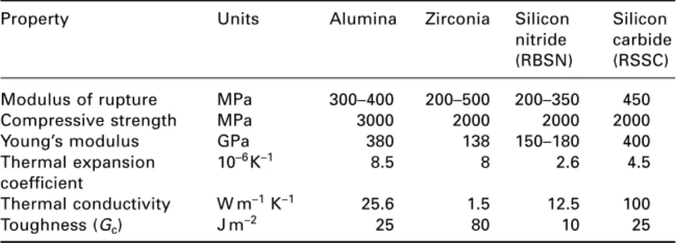
Ceramic materials
- Processing of modern ceramics
- Alumina
- Zirconia
- Nitride ceramics
- Sialons
- Carbide ceramics
This glass can then be crystallized in the grain boundaries of the sialon, so that these materials then have very good creep properties. The process is carried out in a nitrogen atmosphere and the product contains little porosity, although there is a proportion of residual silicon in the microstructure, which limits the strength of the material at high temperatures.
Cement and concrete
- Setting and hardening
- Control of the rate of hydration of cement
- Structure–property relationships in cement and concrete
- High-strength cements
- Reinforced concrete and prestressed concrete
- Durability of concrete
Because they are so small, these pores do not have a large effect on the strength of the cement. By reducing the water/cement ratio in this way, superplasticizers increase the strength of the cement product.
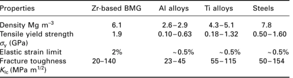
Bulk metallic glasses
Carbonation neutralizes the alkaline nature of the hydrated cement paste and thus removes the protection of steel reinforcement against corrosion. A range of tennis rackets is available that uses BMG in four areas of the frame: the increased stiffness increases energy return by 29%.
Further reading
There are also a number of medical applications of BMG materials, where their biocompatibility and corrosion- and wear-resistant properties are attractive. Composite or bulk metallic glasses that are light and cheap (e.g., Al-based alloys to replace Ti) are being developed for structural applications by a number of research institutions, so their wider industrial use seems likely in the coming years .
Introduction
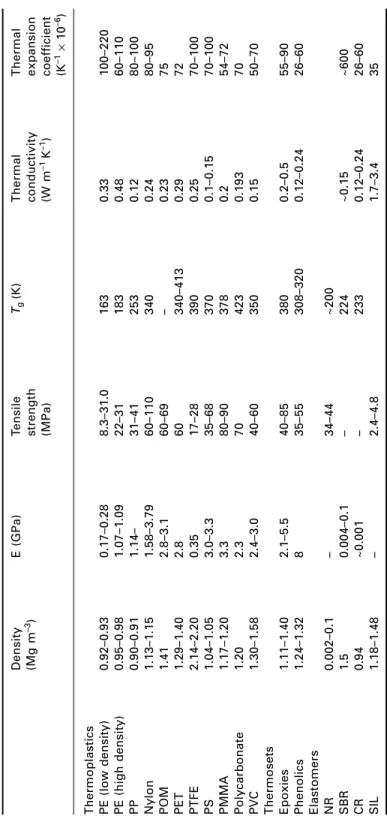
Thermoplastics
Widely used for loose molded objects such as tool boxes and toys; when foamed with CO2, the Styrofoam product is used for packaging and wall tiles. In the form of transparent sheet it is used for aircraft windows and laminated glass; can also be used for external lenses and boards.
Thermosets
Polystyrene (PS) is a very transparent, brittle material with good thermal and dimensional stability and relatively inexpensive.
Elastomers
It has many uses, including seals and gaskets, as well as belts and hoses, and for lining tanks containing certain chemicals. It is used for seals and diaphragms, tubes for food and medical applications, and for electrical insulation over a wide temperature range.
Forming processes for polymers
Extruder-based processes
The deformation and flow behavior of a given polymer (known as its rheological properties) are therefore of great importance and considerable emphasis is placed by engineers on the measurement, presentation and use of rheological data for polymer melts.
Injection moulding
Blow moulding
The top of the parison is cut off by the closure of the mold and the bottom becomes the mouth of the bottle. Air is injected and the inflated parison solidifies into the mold which then opens to eject the bottle and the whole cycle is repeated.
Directionality of properties
Mechanical properties
- Stiffness
- Rubber elasticity
- Yielding
- Material data for polymers
- Fracture
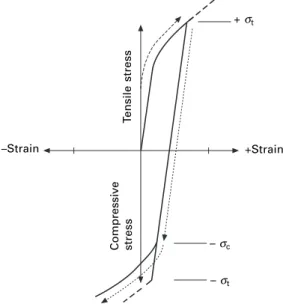
The ordering of molecules according to the applied stress lowers the entropy of the sample. The viscoelastic response of the polymer implies that the corresponding change in strain will be out of phase with the stress.
Joining of polymers
Welding of polymers
The fatigue crack growth (FCG) behavior of a wide variety of amorphous and semicrystalline polymers can be characterized in terms of the stress intensity factor, ∆K, Fig. Fast welding times can be achieved, although joint strength may be compromised by the presence of the heating element.
Adhesive bonding
Mechanical fastening
There is a risk of entrapped air pockets when this technique is used, with consequent risk of breakage during operation if the polymer is sensitive to notching. Thermocouples are too fragile for this technique and tend to crack during use, so you need to use self-tapping screws for these materials.
Polymer degradation
- Oxidative degradation
- Radiation degradation
- Mechanical degradation
- Microbiological degradation
- Chemical attack
This weakens the polymer matrix and the eventual breakdown of the polymer chains reduces molecular weight, amplifying microbial attack. Absorbed moisture has been shown to act as a plasticizer, reducing the glass transition temperature and strength of the polymer.
Modelling of polymer structure and properties