Introduction
Implications of MEMS and Microsystems in Aerospace
The starting point for micro-engineering, depending on standards, could be set sometime in the 15th century, when the first watchmakers began making pocket watches, devices that were micro-scaled after their macroscopic counterparts. MEMS (and we will use MEMS to refer to any micro-machining technique) have had their success in the commercial industries: automotive and entertainment. Initially, pressure sensors and later accelerometers for the airbag were the great successes for MEMS in the automotive industry, reducing costs to just a few dimes.
MEMS in Space
- Digital Micro-Propulsion Program STS-93
- Picosatellite Mission
- Scorpius Sub-Orbital Demonstration
- MEPSI
- Missiles and Munitions — Inertial Measurement Units
- OPAL, SAPPHIRE, and Emerald
- International Examples
The series of MEMS-based Pico Sat Inspector (MEPSI) spaceflight experiments demonstrated the ability to store a miniature (less than 1 kg) inspector (PICOSAT) agent that could be released on command to perform surveillance of the host spacecraft and share collected data with a dedicated ground station. The first iteration of MEPSI PICOSAT was built and flown on the STS-113 mission in December 2002. OPAL also provides a testbed for on-orbit characterization of MEMS accelerometers, while one of the picosatellites is a testbed for MEMS RF switches.
Microelectromechanical Systems and Microstructures
- An Understanding of MEMS and the MEMS Vision
- MEMS in Space Systems and Instrumentation
- MEMS in Satellite Subsystems
- Technical Insertion of MEMS in Aerospace Applications
A general discussion of the potential of MEMS in space applications is followed by a brief exposition of some selected examples of recent MEMS technology developments for future space missions. The paths for the integration of MEMS as well as some of the advanced materials being developed for MEMS applications are discussed. Finally, with an understanding of the concerns unique to space environment hardware, the choice of materials is included.
Conclusion
Muller, Processing of complex microsystems: a micro mass spectrometer, Proceedings of the SPIE — The International Society for Optical Engineering 3680, p. A change in latch state is known as a single event interrupt (SEU). The performance of MEMS devices in space is critically dependent on the characteristics of the radiation environment.
Fuel leaks led to the grounding of the Space Shuttle while on the launch pad. On the right are schematic cross-sectional views of the switch in the "off" and "on" states. The most recent flight of the PICOSAT was on the Space Shuttle (STS-113) in December 2002.
The mechanical properties of the contact material of construction are critical to the operation of the device.
Introduction
Recent MEMS Technology Developments for Space Missions
- NMP ST5 Thermal Louvers
- JWST Microshutter Array
- Inchworm Microactuators
- NMP ST6 Inertial Stellar Camera
- Microthrusters
- Other Examples of Space MEMS Developments
Given the variable heat load dynamics and thermal environment, sizing the radiator is often a challenge. JWST is designed to study the earliest galaxies and some of the first stars to form after the Big Bang. It is clear that NASA researchers have identified several areas where MEMS technology will substantially improve the performance and functionality of future spacecraft.
Potential Space Applications for MEMS Technology
- Inventory of MEMS-Based Spacecraft Components
- Affordable Microsatellites
- Science Sensors and Instrumentation
- Exploration Applications
- Space Particles or Morphing Entities
There are many potential applications for MEMS technology within the U.S. MEMS technology should also play a role in the development of space and surface monitoring systems to support exploration. Clearly, observing, knowing, and predicting the space, lunar, and planetary environments will be important to exploration.
Challenges and Future Needs
Challenges
Future Needs
Significantly more industry-university collaborations, focused on moving MEMS microsystems and devices out of university labs, will be needed to spur the infusion of MEMS technology into future space missions. New techniques for testing materials and methods for performing standardized reliability assessments will be required. The results and test results generated by the testbeds will be used to update MEMS dynamic models.
Conclusions
This information is then used to predict device operation in the charged particle environment of interest.
Introduction
Principles of Heat Transfer
Conduction
By conduction, thermal energy can be transferred through the medium from an area of high temperature to an area of low temperature. The driving force for this type of heat transfer is a temperature difference (temperature gradient), DT. Fourier's conduction law is the empirical equation used to describe conduction heat transfer.
The law states that the rate of heat transfer Q through a homogeneous solid is directly proportional to the surface area A (perpendicular to the direction of the heat flow) and to the temperature gradient dT/dx along the path of the heat flow. The material property that describes heat conduction, thermal conductivity, is typically dependent on the material's temperature. In most space applications, heat conduction in a continuous medium can be correctly described by Fourier's law.
However, the same law is insufficient to illustrate the heat transfer by conduction between two adjacent hardware surfaces. An ``interface thermal conductivity'' is typically used to quantify this effect and is relevant to many MEMS applications. For a complicated case, such as an interface or a complicated structure, the conductivity is measured or modeled and can be used to describe the thermal transport.
The concept of thermal conductivity is important for the thermal design of spacecraft with multiple structures and materials.
Convection
For example, the thermal conductivity for multilayer systems is calculated using the same laws as electrical conductivity.
Radiation
The thermal energy per unit area (W m2) emitted by a body at a given temperature by radiation is called the emissive power of the surface (E). Radiant heat transfer is calculated as a function of the difference of surface emissivities and their corresponding temperature to the fourth power. The surface emissivity («) is the ratio of the actual emissive power of the body to that of an ideal blackbody.
The emissivity depends on the surface material and finish, on the temperature (especially at cryogenic temperatures, where the emissivity drops rapidly) and the wavelength. Tabulated values are available for emissive power; however, measured values are required as actual surface properties may vary as "manufacturing" issues affect the value. In addition, the build-up of contamination or the effect of radiation on the surface can affect the emissivity.
According to Kirchhoff's law, a surface in thermal equilibrium has the property that for a given temperature and wavelength, the absorbance is equal to the emissivity. Since the radiation emitted by a spacecraft falls in the infrared and far infrared regime of the electromagnetic spectrum, the emission is usually given as an average over these wavelengths. Solar absorptivity (a) describes how much solar energy is absorbed by the material and is averaged over the solar spectrum.
Typically, a spacecraft radiator, used to cool the spacecraft via radiation, is constructed from surfaces with high emissivity but low solar absorptivity.
Spacecraft Thermal Control
Spacecraft Thermal Control Hardware
Other common passive thermal control elements include specialized thermal surface finishes, multi-layer insulation blankets, conductivity-enhancing or retarding materials, phase change materials, heat pipes and bimetallic louvers, which open and close according to the radiator temperature. Active thermal control is required when the temperature must be strictly controlled, or when the thermal environment is highly variable. Small satellites can greatly benefit from this approach as they are more likely to be mass produced and require a thermal design that can meet a range of mission criteria.
Heat Transfer in Space
Mechanical devices such as pinwheels, shutters, or shutters that can be ''opened or closed'' to view space can be used to effect such effective changes in absorptivity or emissivity. The main heat sources in the heat transfer process for a spacecraft from space include solar radiation, terrestrial radiation, reflected radiation (albedo) and internally generated heat. For a spacecraft to reach thermal equilibrium in space, the rate of energy absorption or generation and radiation must be equal.
At thermal equilibrium, the heat balance of the spacecraft is at steady state and the derivative dT/dton on the left side of equation (9.7) becomes zero. If we simplify the situation and assume that the spacecraft receives solar radiation as the only source of heat, the heat balance equation (9.7) in the steady state reduces to the following equations: 9:9) According to equation (9.9) for a fixed orientation of the spacecraft and thermal exposure surface temperature becomes a function of surface properties only. This analysis must be repeated for all conditions, as the thermal environment (and internal loading) of a spacecraft typically changes as it moves through its orbit.
MEMS Thermal Control Applications
- Thermal Sensors
- MEMS Louvers and Shutters
- MEMS Thermal Switch
- Microheat Pipes
- MEMS Pumped Liquid Cooling System
- MEMS Stirling Cooler
- Issues with a MEMS Thermal Control
According to the material's coefficient of thermal expansion, heating the beam to a specific temperature causes a differential elongation of the beam. Contact of the beam with the substrate completes the circuit, so that current flows from source to drain. Honeywell's thermal switch can be used to activate an electrical signal when the switch is activated by a temperature change, much like a thermostat.
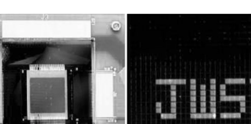
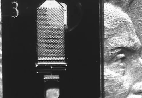
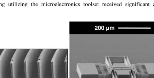
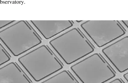
The regulation of the radiator area is achieved by opening and closing slats, which are located directly in front of the radiator surface. MEMS shutters and fins have been proposed very early as a means of thermal control using MEMS for nano and picosatellites.11 The Johns Hopkins University Applied Physics Laboratory (JHU/APL) together with the NASA Goddard Space Flight Center (NASA/GSFC), have designed, manufactured and tested a number of vane designs using the MCNC (now MEMSCAP) MUMP process. Figure 9.1 shows a 3 4 array of MEMS louvres, each 300 500 mm in size, and Figure 9.2 shows the infrared (IR) emissivity at 408C at wavelengths between 8 and 12 mm of the MEMS louvre array with the louvres closed, partially open and open. These slats and a number of other designs such as shutters and folding structure were prototype designs of the concept to be flown on the NASA/GSFC Space Technology-5 (ST5) mission as a demonstration technology for variable emittance coatings (VEC).
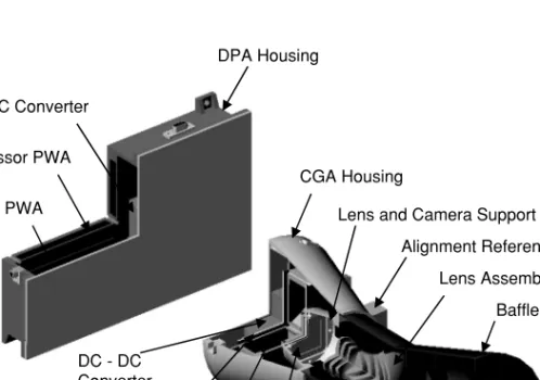
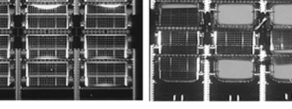
Besides standard passive thermal control, these satellites will carry two VEC experiments, one of them based on a MEMS technology jointly developed by NASA/GSFC and JHU/APL.12,13 These VEC experiments are technology demonstrations and are not part of the thermal control. system itself, but rather independent experiments. The right picture shows some of the louvers open, exposing the high emissivity surface beneath the substrate. The MSA cooler is physically located on the upper deck of the spin-stabilized ST5 spacecraft.
The thermal performance associated with opening and closing the hatches is measured by thermistors located on the underside of the MSA radiator chassis.
Conclusion