This chapter focuses on the architecture and functionalities of the communication subsystem normally found on the satellite. Command and control: receiving and processing commands for continuous operation of the satellite.
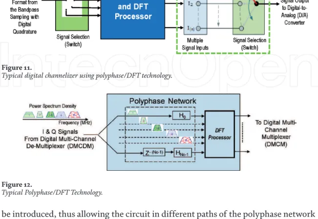
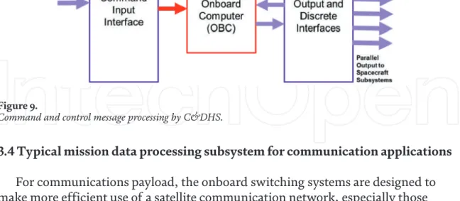
Typical mission data processing subsystem for communication applications For communications payload, the onboard switching systems are designed to
An example of embedded PL processing for passive electro-optical (EO) remote sensing is shown in Figure 11 below, where reflected light from the ground passes through a combination of optical lenses and a charge-coupled device5 (CCD) whose output is an analog signal that would be conditioned by analog filters before being digitized, compressed, and sent down the mission data link to the ground station for processing. Depending on the system, this transmission of mission data down to the ground station can be done using a dedicated direct downlink or indirectly via a relay broadband communications satellite.
Software defined radio (SDR) and applications to satellite
Overview of SDR
Reduced obsolescence: an SDR can be field upgraded to support the latest communication standards. Development on FPGAs can be time-consuming and requires a comprehensive understanding of the target hardware architecture.
Applications of SDR to satellites
- NASA STRS
Hard radical chips are often fabricated on insulating substrates (silicon on insulator, silicon on sapphire, silicon carbide, gallium nitride) instead of conventional semiconductor wafers. 19 SEEs are caused by a single particle of energy and can be (a) Inversion of a non-destructive event (SEU) that causes transients in logic or support circuitry or as bit-slips in memory cells or registers, (b) Single-event latch (SEL) that can be cleared by a single latch of an event (Single-Switch) or Rupture (SEGR), which is irreversible.
Summary and conclusions
Similarly, space-qualified GPP follows the same QML path as FPGA and DSP, and the current on-flight rad-hard GPPs based on the following architecture are [20]. Choosing the appropriate rad-hard FPGA, DSP, and GPP components should be an important factor in design trade-offs when considering SDR for future missions.
Background and introduction
This chapter provides an overview of legacy, existing and future advanced satellite systems for future wireless communications. The review uses a top-down approach, beginning with a comparison between a typical commercial ordinary satellite system and a high-throughput satellite system (HTS), followed by a discussion of commonly used satellite network topologies. In addition, various satellite system architectures using AdBP-DCBS and AR-OBPS payloads for the fifth generation (5G) mobile phone applications will also be presented.
Keywords: high speed satellite, analog bent tube satellite, digital bent tube satellite, digital channelizer and beamformer, advanced regenerative onboard processing satellite, mobile phone. The chapter is organized as follows: Section 2 provides a comparison between commercial HTS and typical satellite systems; Section 3 discusses the typical satellite network topologies; Section 4 presents an overview of legacy ADPS transponder, existing DBPS transponder, AdBPS-DCBS transponder and AR-OBPS satellite system; Section 5 discusses the use of AdBPS-DCBS transponder and AR-OBPS payload for fifth-generation mobile phone (5G) applications; and section 6 concludes the chapter with a summary and brief discussion of the way forward.
Typical commercial satellites and HTS comparison
Typical commercial satellite network topologies
Typical “star” satellite network
Typical “mesh” satellite network
Any of the users in the network can send the messages to a terrestrial network through the red lines representing the uplink and downlink between the satellite gateway and the satellite (Figure 3). Star satellite network topology does not require advanced on-board satellite payload processing and multiple beam, but mesh satellite network requires advanced on-board processing and multiple beam so that one user can communicate to another user automatically and efficiently. Legacy, existing and advanced satellite payload architectures. This section presents an overview of legacy, existing and advanced satellites.
Legacy, existing, and advanced satellite payload architectures This section presents an overview of legacy, existing, and advanced satellite
- Legacy analog bent-pipe satellite (ABPS) payload architecture
- Existing digital bent-pipe satellite (DBPS) payload architecture
- Advanced digital bent-pipe satellite using digital channelizer and beamformer (AdDBPS-DCB) payload architecture
- Future advanced regenerative on-board processing satellite (AR-OBPS) payload architecture
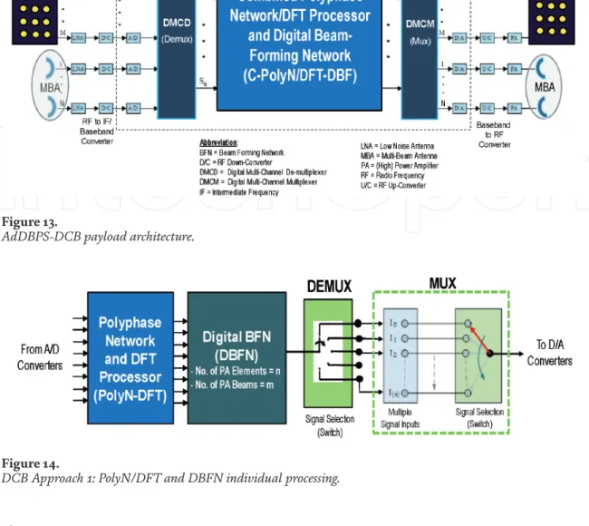
As shown in Figure 9, the main design issue related to digitization and sample processing is choosing the required number of analog-to-digital (A/D) conversion bits to (1) achieve optimal load factor (LF) and (2) minimize quantization noise. LF is defined as the root mean square (RMS) ratio of the total voltage of the converter saturation voltage to the input voltage (RMS). In general, there are two possible approaches of DCB implementation, namely DCB Approach 1 and DCB Approach 2 [13].
DCB approach 1 requires a larger computational load because each DBF processes the entire user link bandwidth (e.g., S1, S2, S3, S4, and S5 in Figure 12 ) at any time to form multiple beams. The AR-OBPS payload can also support digital beamforming, after the frequency division demultiplexing operation, if a phased array is used instead of the analog MBA.
Satellite system architectures for 5G cellular phone applications
AdBPS-DCBS satellite system architecture for 5G applications
The channel codes and modulations used in the uplink (incoming) communication channels need not be the same as the channel codes and modulations used in the downlink transmitted channels. Therefore, an AR-OBPS payload can serve as a "translator" that facilitates one-hop communications between terminals using different connection protocols. However, if the digital multichannel demultiplexer (DMCD) modulator, demodulator, decoder, or digital multichannel multiplexer encoder modulator (DMCM), multiplex functions (MCEM2) are implemented in the ASIC to minimize size-weight and power (SWaP), then some AR-OBPS systems, impossible, unconnected, unconnected, which are supported in relation to below. using communication protocols other than those for which AR-OBPS is specifically designed.
For this reason, AR-OBPS systems are typically deployed in support of "private networks" in which the communications satellite service provider accommodates only terminals designed to operate on the provider's network.
AR-OBPS satellite system architecture for 5G applications
Figure 19(a) shows that AR-OBPS satellite also requires NR interfaces between (1) AR-OBPS satellite and GW and (2) AR-OBPS satellite and 5G-UE. Similar to the AdBPS-DCBS satellite system architecture options, the new NR interfaces between the AR-OBPS satellite and the 5G-UE. Since gNB processing is now placed on AR-OBPS satellite load, the NR interfaces between AR-OBPS satellite and 5G-UE are not the same as those of AdBPS-DCBS satellite and 5G-UE.
To show the differences between the two, Figures 19(a) and (b) use Sat-NG-C and Sat-NG-U to indicate the new radio interface between (1) GW-NGC terrestrial-and-AR-OBPS satellite and (2) AR-OBPS satellite-and-terrestrial GW-NGC, respectively. With decoding-demodulating and encoding-modulating processing onboard the satellite, AR-OBPS enables onboard packet switching and higher quality of service (QOS) than existing DBPS and AdDBPS-DCB at the cost of higher SWAP cost (SWAP-C).
Architecture and Main Components
Introduction
From the author's point of view, this approach has certain advantages arising from Aerospace System Engineering, integration and distribution functions and responsibilities between space mission participants. This chapter presents the SCS from this point of view, integrating conventionally separate satellite GN and C subsystems and units into the common integrated system, Attitude and Orbit Determination and Control System (AODCS).
Earth-orbiting satellites and the role of the control system
It is widely believed that all transport platforms that deliver and carry into orbit are dedicated to the cargo system of a planned space mission, such as a VIP passenger. With its control system (SCS), the satellite provides the payload with all the conditions necessary to carry out the mission (orbit, position, power, pressure, temperature, radiation protection and communication with the ground control center (MCC)). Therefore, from the point of view of mission integration, SCS can be considered as space segment integration bases that place their development and operation process in the appropriate order.
In turn, SCS as a satellite subsystem can also be delineated and established in satellite on-board equipment architecture, combining the group of subsystems dedicated to orbit and attitude determination and control tasks. This can be done from the Systems Engineering rather than the commercial practice point of view and will significantly streamline the order of satellite development and the degree of responsibility of all the developers.
Satellite control system architecture and components 1 SCS architecture
- AODCS components
- AODCS OBCS
It can be used to simultaneously determine satellite position, velocity, orientation and angular velocity. They can usually be one of three pairs in combination with the following three vectors: Earth's magnetic induction vectorB (measured with triaxial MAG), Solar vectorS (measured with biaxial SS) and local verticalr (perpendicular to the local infrared radiation temperature surface, measured with the HS). Three Euler rotation angles, roll (ϕ), pitch (θ), and yaw (ψ), can be expressed by the elements of the matrix Cbr.
After determining the DCM, satellite attitude in three Euler angles can be derived using Eq. The following scheme (which is common in Aviation) can be considered free from the disadvantages above. OBC can be divided into two parts: the hardware (HW, power converter, processor, input/output [I/O] converters, non-volatile and volatile memory) and the software (SW, operating system [OS] and essential or functional software [VS/FS]) (Figure 26).
From (43), it is possible to derive the desired angles and , which can be used to control the position of the satellite.
Conclusion
As can be seen, measured noise is effectively filtered in the control loop and the stabilization error is equal to the sensor bias with opposite sign. In Figure 34, we can see that the measured (perceived) errors that TLM data delivers to ground after the decay time do not present sensor bias and only show measured noise. In general, it can also be seen that the simulation of the approximate second-order model (52) is very close to the exact model (51).
The author also acknowledges the copyright of all publishers of the illustrations that were extracted from the open sources on the Internet. This chapter is distributed under the terms of the Creative Commons Attribution License (http://creativecommons.org/licenses/ . by/3.0), which permits unrestricted use, distribution, and reproduction in any media, provided the original work is properly cited.
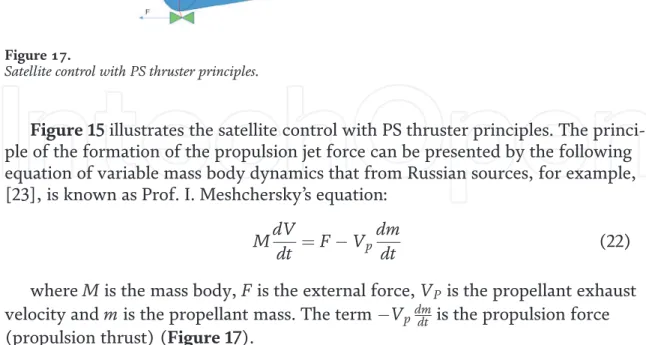
![Figure 17 depicts a potential future AR-OBPS payload architecture [10]. The payload includes (1) a typically set of digitized analog multiple beam antenna (MBA) input signals, digitally frequency division demultiplex each input signal to produce single](https://thumb-ap.123doks.com/thumbv2/1libvncom/9201450.0/36.918.139.783.191.470/potential-architecture-includes-typically-digitized-digitally-frequency-demultiplex.webp)
