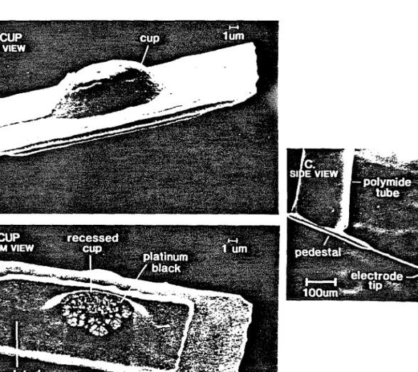
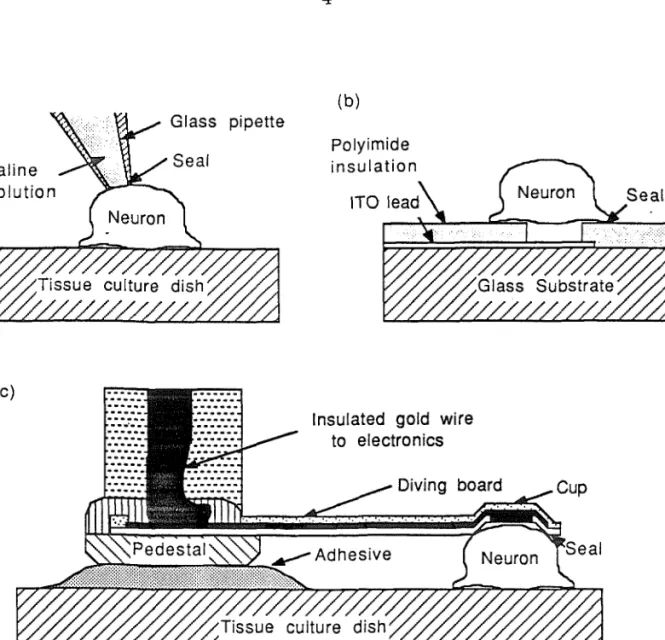
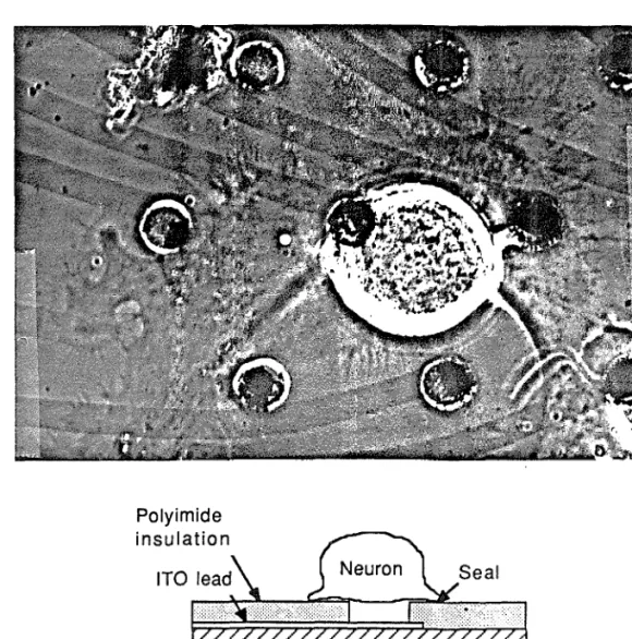
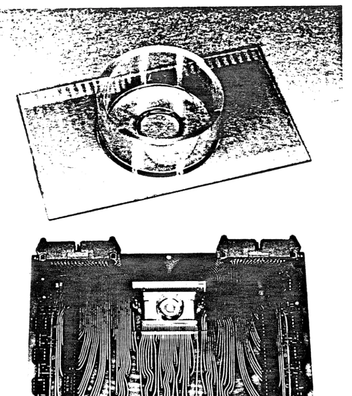
A completed diving board electrode, (a) top view of the cup structure that should fit above the neuron, (b) bottom view of the cup structure, (c) overview of the electrode. The operation of the diving board electrode is very similar to that of a separate electrode [6]. At the resting potential of the cell, Zτ∏2 can be approximated by a parallel capacitor and a resistor.
This is determined by the conductivity of the thin film of tissue culture medium between the edge of the electrode and the cell. For stimulus pulses that are short compared to the cell's time constant (which is typically ≥ 5 msec), the internal voltage change is approximated by. Gluing the diving board to the bottom of the tissue culture dish required an underwater curing biocompatible adhesive.
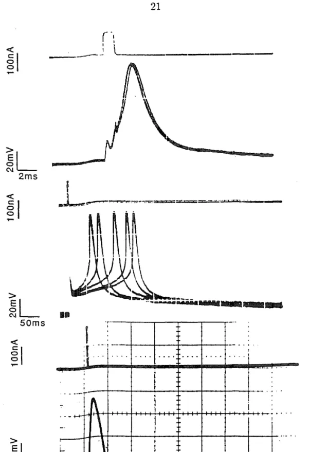
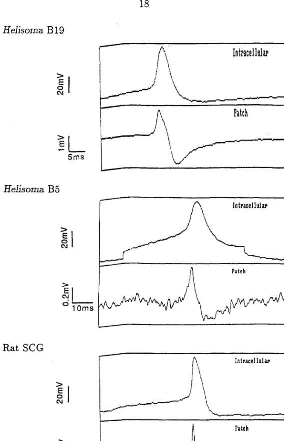
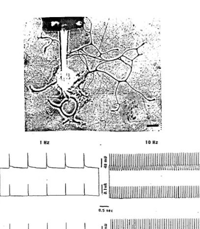
The base is glued to the bottom of the culture dish and the tip of the electrode is in contact with the cell body. A Helisoma B19 neuron stimulated with a current pulse passed through an intracellular electrode, and the cell's response was recorded with an intracellular electrode and a jumping electrode (R3eaι = 4.0 MΩ, bandwidth 10Hz-lkHz).
Introduction
Then the surface of the mass is oxidized in the mixture of sulfuric acid, hydrogen peroxide. The oxide mask also made it easy to accurately determine the depth of the cup. By measuring the masking oxide diameter d3 and the cup tip diameter ⅛ as in Figure A.2, the cup depth can be easily determined, dcup = (d1 — ⅛)∕2.
The depth of the diffusion can be estimated by measuring the distance to the faint line seen in the surface of the silicon after the diffusion. When a boron diffusion is done, a layer of boron glass forms on the surface of the silicon. It is desirable to have as much of the top of the cup etched as possible to reduce the electrode impedance.
Stimulating and Recording From Cultured Neurons With Glass
Cultured identified Helieoma neurons
Cultured rat superior cervical ganglion neurons (SCG ’s)
Cultured SCGs provide an excellent preparation for initial studies, a well-defined trophic factor required for long-term growth, nerve growth factor (NGF), is readily available, (2) ganglia are discrete, readily accessible vessels filled with large numbers of relatively homogeneous neurons, ( 3) they are relatively immature at birth, which facilitates dissociation and culture, (4) they have been extensively studied and characterized both in vivo and in vitro, and (5) the study of such mammalian neurons complements that of the invertebrate Helisoma neurons. While SCGs rarely connect to each other in intact animals, they form extensive connections in dissociated cell culture [18].

Patch electrode tests
The final step is to galvanize the electrode at the bottom of the rocker board with platinum black to make a. The success of the diving board electrodes on SCGs demonstrates their versatility and indicates that they can be used with neurons 20 μm in diameter.
Diving-Board Electrode Fabrication
Micromachining of silicon
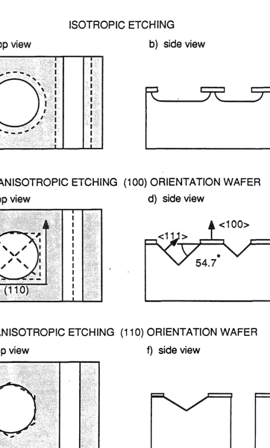
This orientation-dependent etching can be explained by considering the lower-order crystal planes of silicon crystallized in the diamond structure. In the fabrication of the diving board electrode, the anisotropic etch of choice was EDP, used on (100) orientation wafers.
Insulators for saline environments
It is also possible to deposit a compound consisting of the target material that has reacted with the sputtering gas. The second mask defines a pedestal to which the wire bond is attached, and which is glued to the bottom of the culture dish. There will normally be a 25 μτn diameter wire bonded to the gold pad at the back of the pedestal.
Diving board electrodes have been used in this way, but so far the sealing resistances have not been large enough to prevent deterioration of the cell's resting potential. Thus, a positive current pulse hyperpolarizes the patch membrane and depolarizes the rest of the cell membrane. In this way it was possible to compare the intracellular response with the patch pipette response.

Fabrication procedure
Mechanical properties of diving-board electrode
Second, the voltage of the silicon oxynitride layer is adjusted empirically to minimize the beam deflection. So that if it is possible to vary the stress in one of the layers enough to get δ2 = — δ3, the cantilever can be made flat. Twenty-four hours after the device was placed on the neuron, an intracellular electrode was used to monitor the cell's activity and current pulses passing through the electrode were used to stimulate the cell at 1 Hz and at 10 Hz.
Preliminary experiments should be performed using glass patch electrodes of suitable diameter, as flip-board electrodes are valuable and difficult to work with.

Stimulating and Recording with Current-Clamped Loose-Patch
Recording
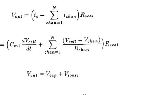
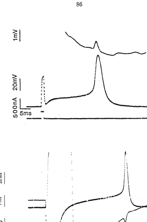
The form of the contribution of the current flowing through sodium channels is given by, <7τvα+(KeZZ — ½vo+)∙ The ion channel contribution can be given by. a) intracellular potential (b) capacitive signal through cell membrane (c) signal through sodium channel (d) signal through potassium channel (e) signal through non-selective efflux channels. The form of the contribution to the current flowing through potassium channels is given by, <7κ+(KeZZ — Vκ+')∙ The contribution per ion channel can be given by assuming a conductance of 10 pS per potassium channel and a maximum drive. For the Helisome B19 neuron of Figure 4.3(a) the signal is essentially a derivative, but the magnitude of the signal is larger by a factor of 10 than would be predicted using the measured derivative of the action potential, the measured seal resistance and the projected membrane area under the patch electrode.
The small negative signal superimposed on the capacitive signal during the rising phase of the action potential is probably due to sodium channels in the patch beneath the membrane.
Stimulation
In addition to the standard x, y, z degrees of freedom provided by a micromanipulator, this special manipulator provides the θ and φ control necessary to make the hopper flat relative to the surface of the tissue culture dish. Except for the inherent electrical differences between Equid-filled electrodes and metal electrodes, jumper electrodes behave like glass electrodes with the same tip diameter for stimulation and recording. Next, the bottom of a small tissue culture dish with a 5 mm diameter hole is glued to the top of the substrate.
The completion of etching can be determined by the rough surface of the etched silicon and the removal of the top chrome layer on the bonding pad, as shown in Figure A.3.

Diving-Board Electrode Tests
Recording from identified Helisoma neurons
With the obtained seals it is possible to record action potentials with good signal-to-noise ratios, but to record signals below the threshold the seal is re. In the experiment of Figure 5.3, where the diving board electrode was mounted on top of a neuron, an intracellular electrode was used to stimulate using a current pulse, and the diving board electrode was used to record the resulting action potential. Signal-to-noise ratios for action potentials recorded from Helisoma B19 neurons were typically 20–100:1, and for Helisoma B5 neurons 4–10:1.
Diving board electrodes were used for up to four days to record spontaneous activity of Helisoma B19 neurons.

Stimulating identified Helisoma neurons
A tipping electrode in electrical contact with a Helisoma B19 neuron. I3tim — 140 nA, ∆t — 0.5 msec, Vpatcfl = 170 mV) Twenty-four hours after the device was placed on the neuron, an intracellular electrode was used to monitor the activity of the cell, and current pulses passed through the electrode were used to stimulate the cell at 1 Hz and at 10 Hz. Recording from a dish electrode below the soma of a Helisoma B19 neuron fired at 0.1 Hz the signal recorded by the dish electrode was essentially a derivative of the action. Write the wafer and glue to a glass slide along with a gold pad to the other end of the wire bond.
Special holders facilitate quick and easy loading of the polyimide tube and insulation of the wire bond.
Tests on Rat SCG’ s
Multielectrode Arrays
Dish Fabrication
Fabrication begins with a glass substrate thick), coated with a layer of ITO (lOOOÂthick, and with a sheet resistance of 100Ω∕square) obtained from Donnelly Corporation (Midland, MI). The photoresist is removed and a 30Â thick layer of aluminum is evaporated onto the wafer, resulting in a thin layer of aluminum oxide that is an effective adhesion promoter. Next photosensitive polyimide (MRK Selectilux HTR 3-50) is spun for 30 seconds at 5000rpm, soft baked for 5 minutes at 85°C, formed with the electrode mask, developed and cured for 12 hours at 200°C.
To reduce the electrode impedances to less than 500 KΩ, the electrodes are platinized in a solution of
Dish Electronics
Experimental Procedure
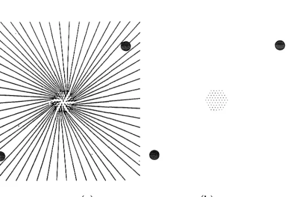
It takes on average about 1 hour to produce each dish, and they were often reused several times, for a total time in salt of 60 days. a) Completed multi-electrode culture dish, (b). Cell bodies moved approximately 100 μm on average after plating, making neuron placement on a specific electrode extremely difficult. When cells were grown as in Figure 6.1, very large lamellipodial seals were obtained on several electrodes.
Recording
However, by using an array with electrodes spaced 70 μm apart, it was possible to seal virtually every neuron to an electrode. As the frequency of stimulation increased to 10 Hz, the signal recorded on the dish electrode changed in two ways: first, the amplitude decreased due to action potential broadening; second, the signal had an ionic component in addition to the capacitive component. Simultaneous recording from dish electrode and intracellular electrode, with the neuron stimulated at 0.1 Hz, 1 Hz, 2 Hz and 10 Hz (bandwidth 10Hz-l kHz).
By stimulating cell A and cell B, we see that the spontaneous activity recorded earlier is not from cell B which is directly above the electrode, but is from cell A.

Stimulation
Such preparations offer the advantage of preserving the architecture found in the brain, while allowing manipulation of the biochemical environment and greater flexibility. This is simplified as the resist is thinner at the top of the cup so only a very low exposure is required to fully etch the top of the cup. As the oxide layer forms, the boron on the wafer surface tends to segregate into the oxide layer, reducing the boron concentration in the silicon surface layer.
The conductive layer is determined by etching, as the adhesion of the conductive layers was consistently better than that of lift-off.
Future Work
Future Experiments with Diving-Board Electrodes
When high sealing resistances have been achieved using glass electrodes without suction, you can use diving table electrodes. Such improvements to the diving board electrode should make it an attractive tool for researchers interested in long-term communication with cultured neurons. Even without the ability to obtain intracellular connections, there are many experiments that can be performed with diving table electrodes involving moni.
This is not the case with vertebrate neurons: diveboard electrodes offer improved signal-to-noise, as well as the ability to record the evoked action potential with the stimulating electrode.
Future Dish Experiments
Long-term electrical connections to cultured SCG neurons should be demonstrated, leading to long-term stimulation experiments on small neuronal systems. Third, preliminary results indicate that voltage-sensitive dyes can be used to map the connection strengths of a system of such neurons, and extracellular electrodes can be used for long-term stimulation. Fourth, spontaneous activity can be monitored continuously and the activity correlated with the connection strengths between the neurons.
These results demonstrate that mapping small systems of neurons using voltage-sensitive dyes is an effective technique.
Future In Vitro Applications of Microdevices
Although the prospect of using dishes to record from and to stimulate slices is attractive, it is extremely difficult: cells within 50 μm of the surface are typically dead in slices, and everything of interest is located well away from the dish's surface. surface. Once the manufacturing and bonding procedures are improved and further studies are conducted demonstrating the general applicability of the flip-board electrode, making this device widely available will be a problem, as the manufacturing procedure requires equipment and expertise well beyond the limits of most . neurobiology laboratories. For long oxide growths, the surface concentration of boron is low enough that the silicon is no longer protected from the EDP and the pedestal is attacked.
This allows the deposition of a film with a well-defined, selectable strain, at temperatures low enough to prevent unwanted alloying of the chromium with the gold.

Impact of Integrated-Circuit Based Micrdevices on Neurobiology