For example, if the HW/SW interface definitions show deficiencies or if the communication between hardware and software designers is insufficient, system integration requires a lot of troubleshooting and re-design. As a consequence, it is possible to explore the entire design space and find an optimal HW/SW architecture.
Google Ara
An incremental amount of temporal information can be added to models in TLM-2.0, which increases model accuracy but slows simulation time. We discuss the use of TLM 2.0 and the hybrid nature of SystemC to provide real-time system simulation, as well as SystemC ports that are cyclically accurate and can communicate with a generic SystemC module.
Organization of Thesis
Embedded systems developed today are composed of hardware and software specific to an application, which are co-developed, usually on a tight schedule. SystemC was developed to provide features that help the modeling of hardware, especially the parallelism of hardware in a mainstream programming language.
SystemC Basics
After gaining control, the kernel can increase the simulation time or queue a process to be executed at the same simulation time. Thus, a process that does not callwait() will not give its control to the kernel, and the simulation time will never increase.
TLM-2.0
Coding Styles
Loosely Timed (LT) models are where each transaction has only two time points, marking the start and end of the transaction. Simulation time is used, but to increase simulation speed, processes are allowed to run ahead of simulation time, so they are temporarily disconnected. An LT (free-time) approach is most likely to consist of Blocking calls, and an AT (approximate-time) approach uses non-blocking calls.
The speed of the offered simulation is also in between these two approaches, as shown in Figure II.3. These modules connect to the anendoskeleton, which has a locking mechanism and connection ports for the module's interaction with other phone components.
![Figure II.3: Speed vs. Coding Style [15]](https://thumb-ap.123doks.com/thumbv2/123dok/11039370.0/14.918.317.649.111.442/figure-ii-3-speed-vs-coding-style-15.webp)
Unipro
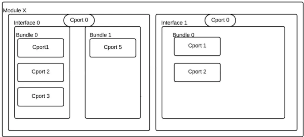
Not only does this provide ease of use to the users, but it also significantly reduces electronic waste and leads to longer life cycles for the mobile phone. On top of UniPro protocol is built the Greybus protocol which provides semantics to the communication packets. A cport is a 5-bit identifier, which is analogous to the port number in a TCP or a UDP connection, and serves as a subaddress within a UniPro device.
Each UniPro device has multiple Cports associated with different protocols as shown in Figure III.1. Continuing our previous analogy with TCP/UDP, since messages intended for different protocols are forwarded to the respective port numbers (eg 8080 for HTTP), messages intended for different protocols are forwarded to their respective Cport number [1].
![Table III.1: Unipro Protocol Stack [1]](https://thumb-ap.123doks.com/thumbv2/123dok/11039370.0/16.918.166.840.140.358/table-iii-1-unipro-protocol-stack-1.webp)
Endoskeleton
When a new module is inserted, the only way to communicate with the system is through this SVC. The SVC has direct control and responsibility for the network, including detecting when modules are present, configuring the UniPro switch, enabling module interfaces, and attaching and detaching modules. The AP Module controls the endo through operations sent over the SVC connection, and the SVC informs the AP Module of endo events (such as the presence of a new module or notification of changing power conditions).
Greybus
Greybus Operation and Setup
A battery needs a single Cport to talk to the AP, but Wi-Fi needs a multitude of Cports. The AP instructs the SVC to bind one of its Cports to Cport 0 on the inserted module. Until now, the AP has no information about the number of Cports and the type of protocols it will use.
These descriptions define the number of Cports, the protocols supported and the number of bundles, to the AP. By reading the Manifest, the AP Module establishes the connections named in the Manifest and also instructs the SVC to reconfigure the UniPro switch to route the messages to the correct destination.
![Table III.2: Greybus Header Format [13]](https://thumb-ap.123doks.com/thumbv2/123dok/11039370.0/19.918.256.717.139.258/table-iii-2-greybus-header-format-13.webp)
Special Protocols
Device Class and Bridged PHY Protocol
Summary of the ARA System
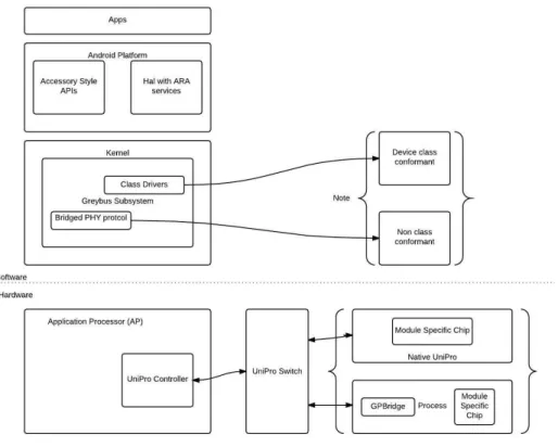
On the software side, we have the Greybus subsystem, which sits on top of the UniPro protocol stack. The Greybus system also talks to the modules in two primary ways that are analogous to the two ways defined in the hardware side defined earlier. These are the Device Class and the Bridged PHY protocols that allow direct communication or communication via a bridge respectively.
However, any device that does not conform to the device class uses the Bridged PHY protocol and connects to the UniPro bus via the GPBridge. It also seeks to allow the user to attach Android applications to the system so that the system can be simulated as it would exist in the real world.
Challenges
Then it describes the Systems Model divided into four parts and our approach to countering these challenges with each part in detail.
System Model
- Development Kit
- USB-Bridge
- SystemC Application
- User Module
This part is necessary because the Greybus core modules can connect a USB device to it. To counter this problem, the Greybus messages embed the Cport number in its reserved bytes. The details of the tasks performed by the USB bridge are detailed in section IV.3.
A GPbridge is a bridge between the Greybus messages and the modules that support the legacy protocol. The primary purpose of this application is to receive Greybus messages coming from the AP, process them and present them to any other module as a legacy protocol.
Tasks performed by USB-Bridge
Initial Setup
These steps perform the basic plumbing necessary for the Development Kit and the USB Bridge to work together as an AP module and SVC. As the gadget is activated, it waits for the Greybus core modules to bind the drivers. The Gray bus core module sends an Interface and Device ID for the SVC, which are hardcoded as 0 and 1 respectively.
This means that any message for Cport 0 and Device ID 1 is intended for the SVC. Interface Device ID 0x01 Sent by the AP, It provides the device ID that the SVC should associate with the specified interface.
Insertion of Module
Interface Hotplug 0x02 Send with SVC when a module is inserted Hot Interface Unplug 0x03 Send with SVC when a module is removed Reset Interface 0x04 Send with SVC to reset a particular connection. Connection Create 0x05 Send from AP to SVC, indicating it to create a connection between Cports Connection Destroy 0x06 Send from AP to SVC, indicating it will destroy a connection between Cports. USB-Bridge now parses the Manifest blob and stores its information in a structure that replicates the Manifest description as shown in Table IV.2.
Since there are many interfaces and there is no information about the interface ID in the manifest, the interface ID (IID) is given in the manifest file name. Extracts this IID and sends a request for the interface ID. The device ID is coded to “2”.
After the Insertion of Module
This information on an actual system is known to the SVC because interfaces are hardware connection points that are sequentially arranged around the device. The Manifest filename must be of the format "IID#*" where # represents the ID the user wants and * represents any valid character for a filesystem. The USB-Bridge then creates another thread that monitors data from the TCP connection that closes the previous thread.
The difference between these two threads is, although they both monitor the TCP connection, the first thread expects a filename and goes through the initial configuration, the second thread assumes that the initial configuration is done and simply forwards the Greybus messages it receives, to the AP.
SystemC Application Design
- Block Diagram
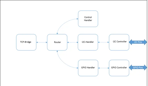
- TCP-Bridge
- Router
- Control Handler
- I2C handler
- I2C Transfer Operation
- I2C Controller
Essentially, the entire system operates on a quantum of 2 ms. The system advances the SystemC clock (simulation time) by 2ms (by callingwait()), and then it slows down the real clock by this time to catch up with simulation time. Control Handler takes care of the Control Protocol which is a special protocol defined in the Greybus system. It is used by the SVC to do initial probes of the interface when the system is powered on.
Get Manifest Size 0x03 Used by the AP, on hotplug event, to determine the size of the manifest. Functionality 0x02 Allows the requester to determine the details of the functionality provided by the I2C controller.
Implementation Details
The most important aspect for practical applicability is that the system must run in real time and be able to connect to generic modules without knowledge of the underlying Greybus system. Finally, we present the result of the communication traces between this test module and our framework. When the SystemC application runs, it asks for the Manifest file of the module under test and the IP address of the USB Bridge.
It connects to the USB bridge and sends the Manifest file name to indicate insertion of a module.
The Compass Module
If we insert a Manifest that supports the I2C protocol, we can see that a device pretending to be an I2C device appears on Linux devices.
Communication Traces
The Ara project uses the UniPro protocol for communication between modules and the Greybus protocol to provide semantics to the UniPro protocol. The thesis describes the data packet flow from an application processor to the module supporting a legacy protocol. Messages travel from a processor running an Android stack via a USB cable to the USB-Bridge, which models the SVC controller.
It also provides SystemC ports for connecting a generic module to the application that supports a legacy protocol. Finally, as an example, a model of a compass that supports a compass is designed and connected to the SystemC Application.
Future Work
The framework in this thesis simulates the GPBridge and allows external user-defined modules to be connected to it. In doing so, it also simulates the endoskeleton and the Supervisory Controller (SVC) of the Greybus system. They now go along a TCP link to SystemC application where they are processed, and results are returned.
The SystemC application is modeled as an abstraction of GPBridge using TLM 2.0 and the free-time coding style. Also, an Android application is installed on the Android device which communicates with an I2C device.
Generic Payload [4]
Unipro Protocol Stack [1]
Greybus Header Format [13]
SVC Operation Types [13]
Manifest Descriptor [13]
Descriptor Types [13]
Control Protocol Operations [13]
I2C OP [13]
I2C protocol Operation Types [13]
I2C Protocol Transfer Request [13]
Key components in an OSCI TLM 2.0 model [5]
TLM 2.0 Classes [12]
Speed vs. Coding Style [15]
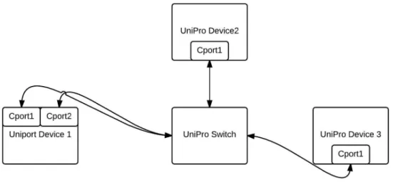
Example system architecture showing multiple UniPro devices connected via UniPro switches 10
Logical parts of a module
Network Stack over software and Hardware
Top Level Abstract Model
Top-Level Model of SystemC Application
Compass Module Flow Chart
I2C data transfer over a period of 20 ms
Zoomed wave form of a single I2C transaction
![Figure II.1: Key components in an OSCI TLM 2.0 model [5].](https://thumb-ap.123doks.com/thumbv2/123dok/11039370.0/12.918.303.676.98.371/figure-ii-key-components-in-osci-tlm-model.webp)
![Table II.1: Generic Payload [4]](https://thumb-ap.123doks.com/thumbv2/123dok/11039370.0/12.918.330.641.759.950/table-ii-1-generic-payload-4.webp)
![Figure II.2: TLM 2.0 Classes [12]](https://thumb-ap.123doks.com/thumbv2/123dok/11039370.0/13.918.189.787.110.556/figure-ii-2-tlm-2-0-classes-12.webp)
![Figure III.2: EndoSkeleton [9]](https://thumb-ap.123doks.com/thumbv2/123dok/11039370.0/17.918.192.756.287.694/figure-iii-2-endoskeleton-9.webp)