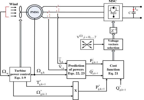
The proposed cost function consists of the absolute deviations between the reference and actual generator voltage components. In addition, the design of the battery storage control system and the PV inverter are also presented and described. 𝑄𝑔,𝑟𝑎𝑡 to equalize the importance of each monitored term is important to the other (ie, the monitored terms are not similar in nature).
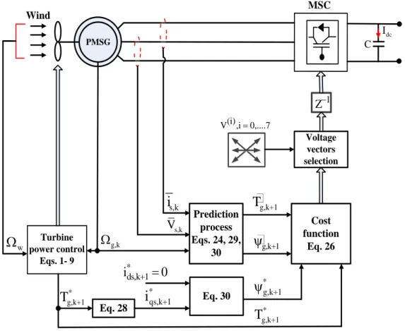
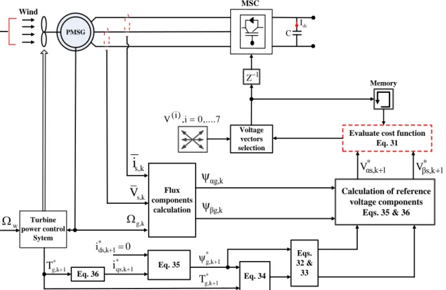
Mossa (Performance improvement of a hybrid renewable energy system accompanied by energy storage device using an efficient control system). 𝑇 ) 𝑇𝑠 (25) The MP DPC system layout used to control the operation of the PMSG is then structured in Fig. Consequently, the cost function used by MP DTC consists of the normalized torque and flux errors together with a weighting coefficient 𝑤𝑐′ = 𝑇𝑔,𝑟𝑎𝑡. The control system structure of the MP DTC is then constructed using the presented formulas as shown in Fig.
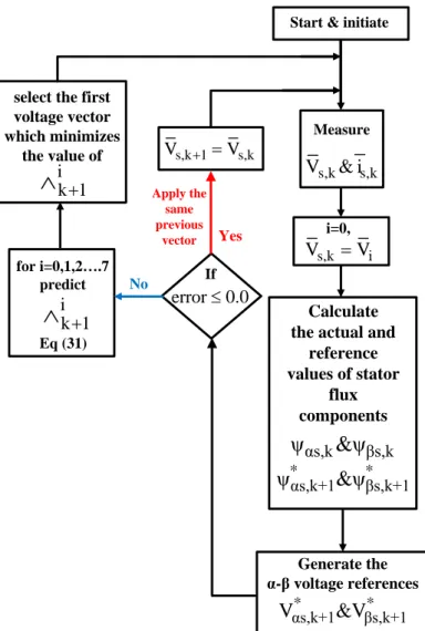
The controlled variables of the cost function are the absolute errors of the generator voltage components 𝛼 − 𝛽, which can then be expressed by. Current voltage components 𝑉𝛼𝑠,𝑘+1 and 𝑉𝛽𝑠,𝑘+1 can be obtained with the help of finite control set (FCS) principle [48][49]. A flow chart summarizing the operation steps of the proposed predictive control scheme is illustrated in Fig.
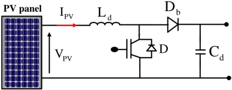
The converter topology of the DC/DC Boost Converter used for converting the electrical energy obtained from the PV array is shown in Fig.
Energy Management Strategy (EMS)
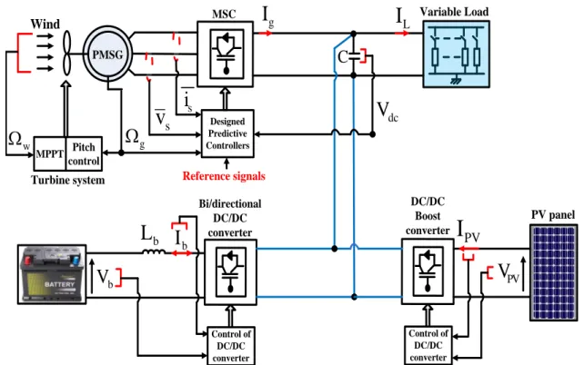
To protect the battery from overcharging, limiters are used that help keep the battery power within the allowable maximum limits. The excess power 𝑃𝑆𝑢𝑟 cannot be stored when the battery is fully charged or 𝑃𝑆𝑢𝑟> 𝑃𝑏,𝑚𝑎𝑥, so it must be limited. This action can be achieved by reducing the generation of renewable energy by preventing control systems from operating at maximum power points or simply by switching off the selected generation sources.
In this situation, excess power can be dumped into additional power loads specifically connected to the system. There will be a power shortage 𝑃𝐷𝑒𝑓 = [𝑃𝐿− (𝑃𝑔+ 𝑃𝑃𝑉) ] in the system if the total generated power (𝑃𝑔+ 𝑃𝑃𝑉) is lower than the load capacity 𝑃𝐿. Due to the limited capacity of the battery, this state can only be reached for a certain period of time.
The battery capacitance must be calculated for a period of no energy production or a reduction in the value of the generated energy.
Test Results
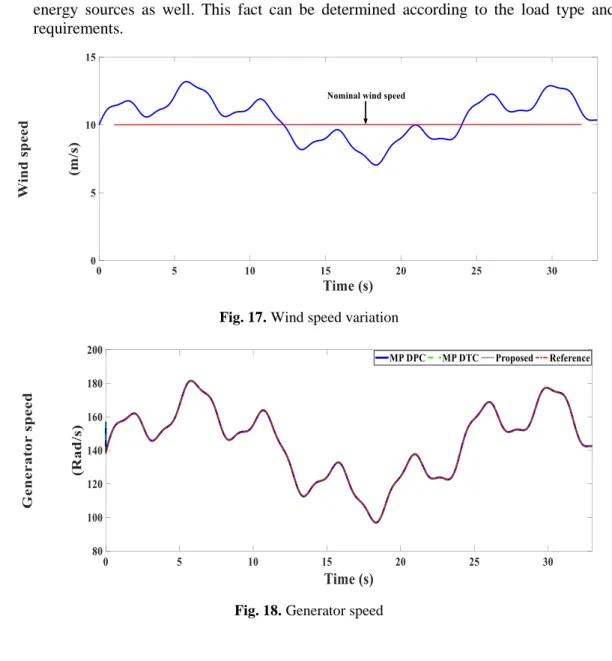
Consequently, the results are presented systematically: starting with the dynamics of the wind turbine system, continuing with the analysis of the PMSG performance, and ending with the analysis of the EMS performance. The results are obtained considering the three predictive controllers (MP DPC, MP DTC and the proposed controller) with PMSG and considering the MPPT algorithm with the PV generation system. 18 illustrates the generator shaft speed using the three predictive controllers, from which it is understood that the PMSG speed follows the wind speed change exactly, which proves the effectiveness of the built wind turbine system.
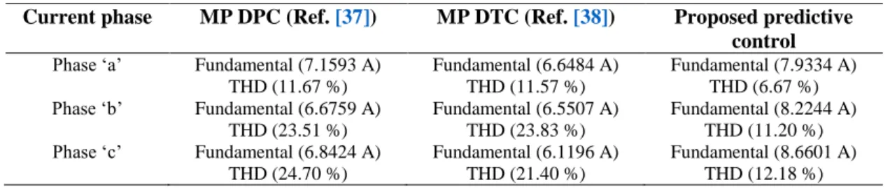
The dynamics of PMSG using the three predictive controllers are also investigated to visualize and confirm the superiority of the proposed predictive controller. 24 illustrates the active and reactive power profiles, and a detailed view of the power dynamics, respectively. In order to carry out a more detailed investigation of the performances of the three predictive controllers, the fast Fourier transform (FFT) analysis is performed for the stator currents, and the THD values are recorded in Table 1.
The comparison between the three predictive controllers used for controlling the PMSG can also be done in terms of the number of commutations performed. This factor is considered a measure of the computational load that each controller can provide. Accordingly, the statistics are covered in Table 2, confirming the superiority of the proposed predictive controller over the MP DPC, and MP DTC approaches achieving remarkably low commutations.
35 show the power or current flows between the system units according to the three used PMSG controllers. In stage 2, the load is increased and covered by the sum of the wind and PV generated powers. In stage 4, the load is reduced; wind and PV power almost cover it with a slight shortfall covered by the battery.
In phase 7, the load is reduced and the generated power of the PV and wind system is much higher; consequently, to achieve balance, the excess power charges the battery. 36, confirming the effectiveness of the control systems designed to keep the voltage very concise with the reference value (400 V). In addition, the superiority of the designed predictive controller over the MP DPC and MP DTC in controlling the PMSG dynamics is also confirmed.
Conclusion
El-Fouly, "Renewable Energy Management System: Optimal Design and Hourly Dispatch," IEEE Transactions on Sustainable Energy, vol. Hossain, “Cost-Aware Off-Grid Sustainable Base Stations Assisted by Renewable Energy with Energy Cooperation,” IEEE Access, vol. Padhy, “Effective control and management scheme for isolated and grid-connected DC microgrid,” IEEE Transactions on Industry Applications, vol.
Lee, “Hierarchical distributed model predictive control of stand-alone wind/solar/battery system,” IEEE Trans. Panigrahi, "Performance Investigation of Multifunctional On-Grid Hybrid Wind-PV System with OASC and MAF-Based Control," IEEE Transactions on Power Electronics, vol. Lenwari, "Optimal Design of a 5-MW Double-Stator Single-Rotor PMSG for Offshore Direct Drive Wind Turbines,” IEEE Transactions on Industry Applications , vol.
Bissochi, "Evaluation of Capacitor Bank Design for Self-Excited Induction Generators," IEEE Latin America Transactions, vol. Roskilly, "Voltage Build-Up Analysis of Self-Excited Induction Generator With Multi-Timescale Reduced-Order Model," IEEE Access, vol. Sun, “Subsynchronous Oscillation Suppression Strategy for Dual-Feed Wind Power Generation System,” IEEE Access , vol.
Zaki Diab, "Cost-Effective Predictive Flux Control for a Sensorless Double Fed Induction Generator," IEEE Access, vol. Mohamed, "Investigating the Effects of Wind Source Dynamics and Stability Options in DC Wind Energy Conversion Systems," IEEE Access, vol. Pillai, "Low- Voltage Ride-Through of a Synchronous Generator-Based Variable Speed Grid-Interfaced Wind Energy Conversion System,” IEEE Transactions on Industry Applications, vol.
Cardoso, “Fault-tolerant back-to-back inverter for direct-drive PMSG wind turbines using direct torque and power control techniques,” IEEE Transactions on Power Electronics, vol. Zanchetta, "PWM-based Optimal Model Predictive Control for Variable Speed Generating Units," IEEE Transactions on Industry Applications, vol. Yang, “Model predictive control of PMSG-based wind turbines for frequency regulation in an isolated grid,” IEEE Transactions on Industry Applications , vol.
Kennel, “Multiple-vector model predictive power control for grid-tied wind turbine system with improved steady-state control performance,” IEEE Transactions on Industrial Electronics, vol. Cardoso, “Improved and Computationally Efficient Model Predictive Flux and Power Control of PMSG Drives for Wind Turbine Applications,” IEEE Transactions on Industrial Electronics, vol.
![Fig. 3. (a) PV cell circuit model. (b) PV array circuit model The output cell current 𝐼 𝑃𝑉 𝑐 can be calculated at instant KT s by [46]](https://thumb-ap.123doks.com/thumbv2/123dok/10235609.0/7.892.139.781.505.706/circuit-model-circuit-output-current-𝑃𝑉-calculated-instant.webp)