Neurons and Neural Networks
Neurons
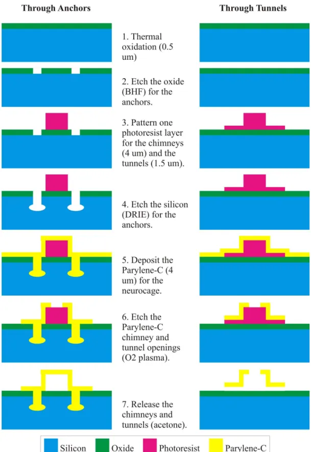
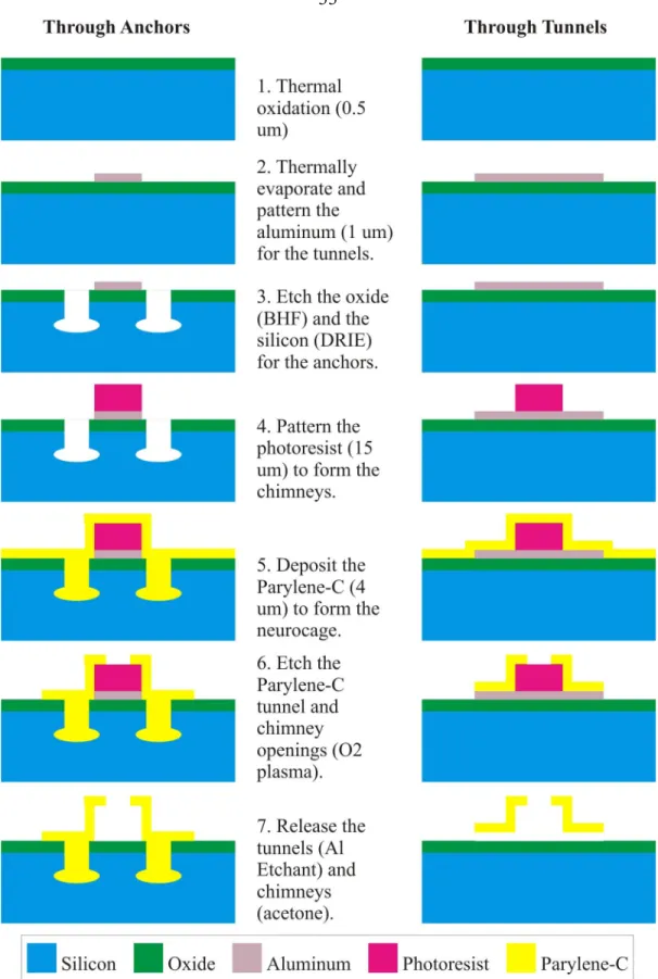
To counteract the difficulties encountered with the neuro-well, we developed the neurocage (Figs. 1-2), which is the focus of this thesis. When the top layer of photoresist is subsequently exposed, the bottom layer is exposed again (ie, the bottom layer is overexposed). To eliminate the problem in the previous process (section 3.3.1), the anchors in this process are etched in two separate steps.
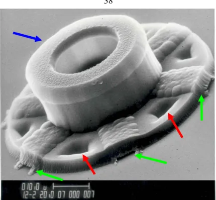
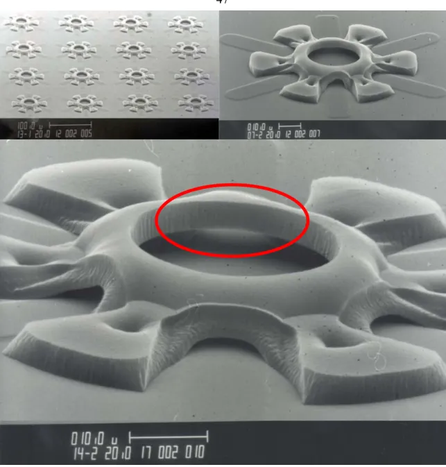
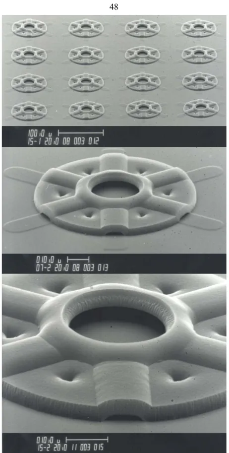
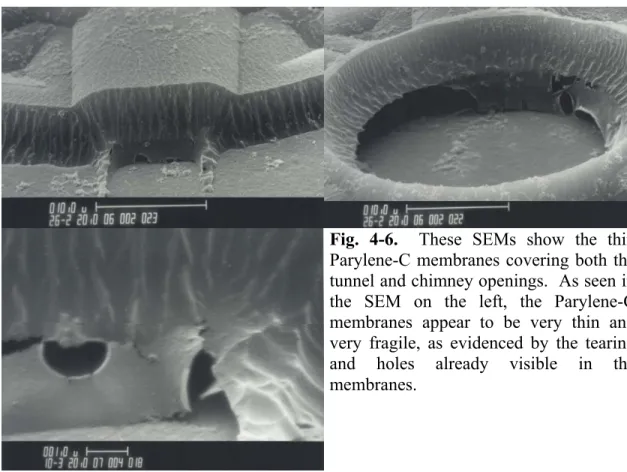
Assuming that sufficient amount of Parylene-C insulation remains after the tunnels are etched open and there are no holes in the insulation layer (i.e., no Parylene-C. As seen in SEM (Figs. 4-6), the curtains appear to be very thin and fragile. This graph shows the response of the neural network after one of the neurons (Channel 14) is stimulated with a 12 µA current pulse. The graph shows an overlay of the response of the neural network for 5 separate trials.) Impulse current is applied at t = 40 ms.
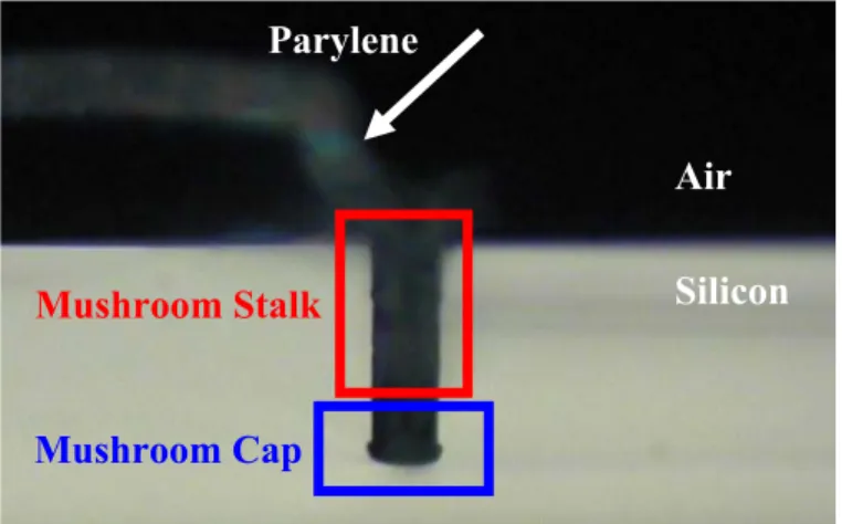
Next, the first layer of Parylene-C (0.5 µm thick), used to create the inverted mushroom for the anchors, is deposited. These steps do not require the glass slide to be attached to the wafer.) The Parylene-C is then annealed at 350°C in an N2 atmosphere for 2 hours. The Newton rings around the anchors indicate that the glass has been etched beneath the Parylene-C, creating the desired inverted mushroom structure. subsequent layers of aluminum adhere well.
Patch-Clamp Recording Technique
Multi-Electrode Arrays (MEAs)
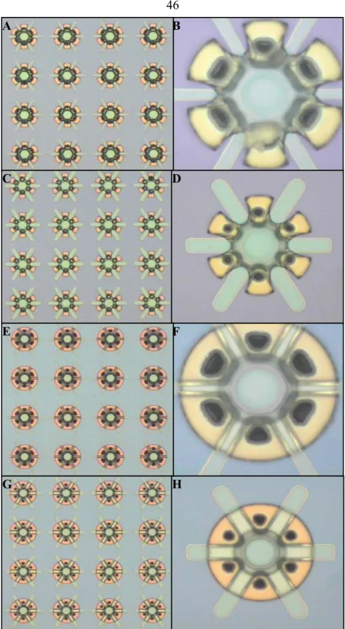
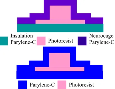
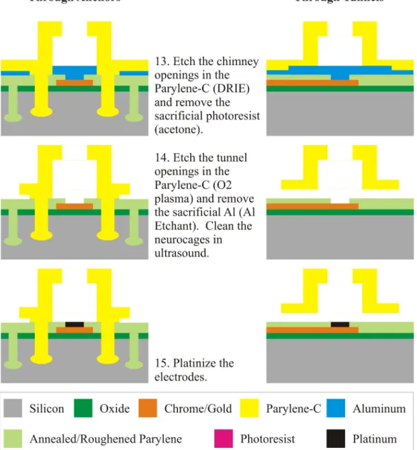
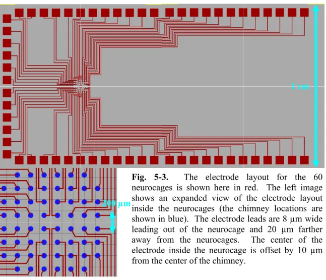
The size of the neurons used for the experiments determines the dimensions of the tunnels and chimney. The breakdown of the manufacturing process for the neurocages with Parylene-C insulation is shown in Fig. The right image shows an enlarged view of the electrode layout within the neurocages (the chimney locations are shown in blue).
The left image shows a magnified view of the electrode layout in the neurocages (the chimney locations are shown in blue). This layer is then baked in a nitrogen atmosphere (N2) at 350°C. The N2 atmosphere ensures that Parylene-C does not oxidize and turn brown.) This temperature is above the melting temperature of Parylene-C, causing it to melt and recrystallize [30]. The right image shows a close-up of the electrodes for the 4 neurocages in the center.
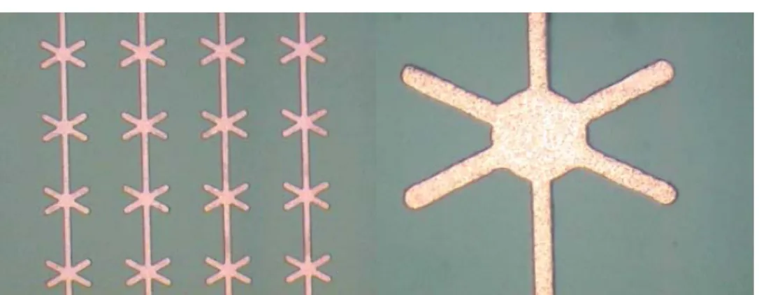
Optical images of neurocage anchorages etched through Parylene-C insulation and into glass.
Neuro-Well
Neurocage
MEMS Fabrication Technologies
Fabrication Technologies
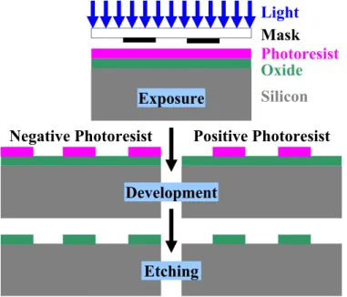
- Photolithography
- Oxidation
- Thermal Oxidation
- Sputtering
- Etching
- Wet Etchants
- Dry Etchants
- Evaporation
- Chemical Vapor Deposition (CVD)
Parylene
- Parylene Deposition
- Parylene Properties
Several steps were included in the fabrication process to improve the adhesion of parylene-C.
Neurocages on Silicon without Electrodes
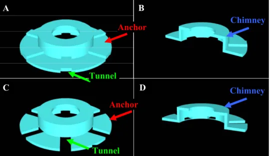
Design Components
- Anchors
- Tunnels and Chimneys
- Sacrificial Materials
- Neurocage Arrays
Aluminum Sacrificial Material
- Fabrication
- Culturing Results
The bottom layer of photoresist (in green) is exposed before spinning onto the top layer of photoresist (in pink). By soft-baking the top layer of photoresist at a lower temperature, the outgassing of the chimney's photoresist is minimized.
Hard-Baked Photoresist Sacrificial Material
Electrode leads are 8 µm wide leading out of the neurocages and 20 µm away from the neurocages.
Neurocages on Silicon with Electrodes
Insulation Materials
As you can see, they have similar dielectric constants, indicating that they will behave similarly to insulators. Although Parylene-C was the primary insulator, some later fabrication was also done with low voltage silicon nitride insulation. Low voltage silicon nitride is an alternative to standard silicon nitride as standard silicon nitride can be and is a high voltage material.
However, Parylene-C and low-stress silicon nitride were almost indistinguishable from each other with respect to action potential detection and neuronal survival rate.
Parylene-C and the Aluminum Etch Stop
- Closed Tunnels
- Roughened Parylene-C Insulation
- Aluminum Etch Stop
If too much Parylene-C is etched, the tunnels will definitely be open, although the Parylene-C that remains as the insulation for the electrodes will be too thin or have holes (caused by the same O2 plasma that opened the tunnels) ( Fig. 4)-3A). As previously mentioned, when the Parylene-C is deposited for the neurocage, it forms a single layer with the Parylene-C insulation. Unlike the previous problem, the closed tunnels, this problem cannot be solved by careful etching of the Parylene-C.
This etch stop is a material deposited on top of the Parylene-C insulation prior to neurocage fabrication that serves to keep the Parylene-C insulation and neurocage layers separate.
Moats, Curtains, and Melted Chimneys
- Moats
- Curtains
- Melted Chimneys
- Resulting Neurocages
Of the methods tested, chromic acid and an ultrasonic bath in water (for short periods) were the only ones that successfully removed the curtains without also removing the neurocages. Since the ultrasonic bath in water is the simpler method, it is included in the manufacturing process as part of the final cleaning step to remove the curtains from the tunnel and chimney openings. Although the curtains were removed, the O2 plasma roughened the Parylene-C and created a "fuzzy" neurohog that hindered visualization of the neurons.
The separation between the tunnel and chimney etching steps ensures that the chimneys are not over-etched and have clean openings.
Parylene-C Bubbling
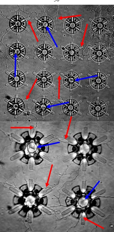
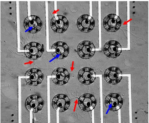
Originally, the electrode inside the neurocage was designed to cover virtually the entire floor of the chimney. The neuron extended its axon (indicated by the blue arrow) through the tunnel and then the neuron body (indicated by the red arrow) followed its axon right out of the neurocage. Since the electrode is in the exact center of the chimney, the area in which the neuron.
If the insulation is silicon-nitride, a brief O2 plasma treatment is used to ensure that all photoresist is removed from the electrode leads. If the insulation is silicon-nitride, a brief O2 plasma treatment is used to ensure that all photoresist is removed from the neurocage anchors. The center of the electrode within the neurocache is displaced by 10 µm from the center of the chimney.
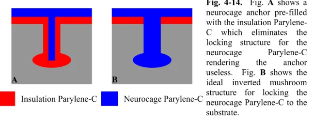
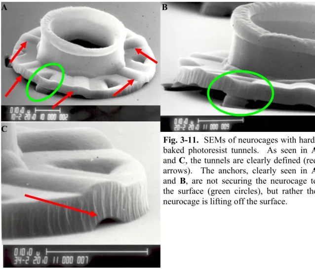
Anchors
Neurocage Design
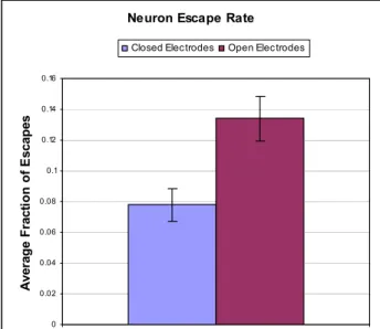
- Neuron Escape Rate
- Tunnel Sacrificial Material
- Platinized Electrodes
- Chimney Diameter
- Parylene-C Insulation Thickness
- Neurocage Electrode Location and Anchors
- Final Neurocage Deign and Electrode Layout
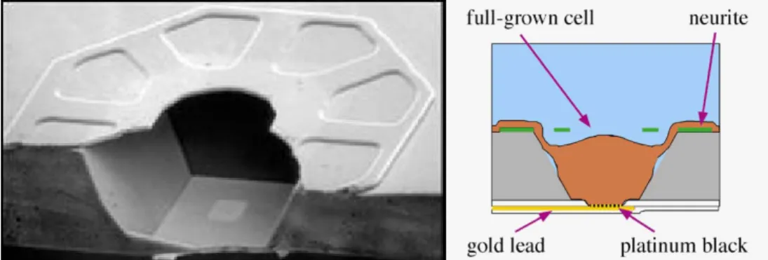
As the neuron moves away from the electrode, it compresses itself against the rim of the neurocage's chimney. The platinization on the electrodes forms a thin spiky bush structure on top of the electrode. One solution to this problem is to move the electrode to the edge of the chimney instead of the center.
The electrode within the neurocache is 14 µm in diameter with a 10 µm diameter via, spaced from the center of the chimney by 10 µm.
Fabrication Process
A single layer of photoresist, approx. 4 µm thick, spun on, soft baked at 100°C for 30 minutes and patterned to form the openings for the insulation anchors. A single layer of photoresist, approx. 4 µm thick, centrifuged, soft baked at 100°C for 30 min and patterned to form the openings for the neurocage anchors. If the insulation is silicon nitride, bake the wafer at 100°C for 10 minutes and treat with HMDS for 1 minute.
Next, for Parylene-C isolation, a 4 µm thick layer of photoresist is spin coated and gently baked at 100°C for 30 minutes.
Culturing Results
In addition, due to the transparency of Parylene-C, it is possible to see neurites when they are in tunnels. The survival rate for neurons in these neurocages is good, nearly 50% even after 3 weeks (Fig. 4-34). Red arrows indicate some of the neurites extending outside the neurocages. that were alive on day 2), the survival rate increases to nearly 75% after 3 weeks.
Electrical Stimulation and Recording
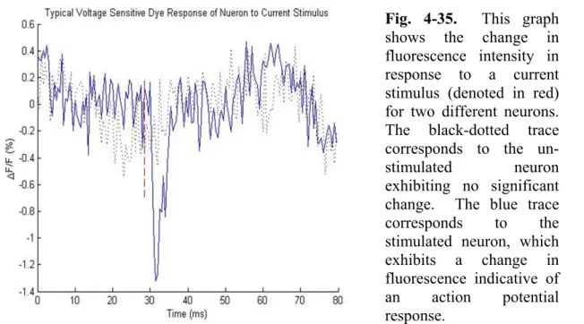
The neurons in this experiment are 14 days old, although recordings were made in cultures up to 4 weeks old. This graph shows the change in fluorescence intensity in response to a current stimulus (marked in red) for two different neurons. The blue trace corresponds to the stimulated neuron, which exhibits a change in fluorescence indicating an action potential response.
Thus, stimulating the neuron on Channel 14 does not stimulate a response in all of the remaining 15 neurons in the array.
Long-Term Impedance Testing
Therefore, it is reasonable to expect that neurochips will continue to function normally for more than 4 weeks when used at 37°C. Given that cultured neurons generally do not survive longer than about 4–5 weeks, the lifespan of these devices is more than adequate. The graph also shows that the logarithm of electrical impedance is linear over a given frequency range.
Therefore, the log of the electrode impedance is expected to be linear.
Future Work
The glass chip is attached to the wafer with photoresist and baked for 10 minutes at 100°C. The glass chip is attached to the wafer with photoresist and baked for 5 minutes at 100°C. Again, the glass chip is attached to the wafer with photoresist and baked at 100°C.
Finally, the photoresist is removed and the glass slide is removed from the wafer in acetone.
Neurocages on Glass with Electrodes
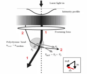
Laser Tweezers
A laser beam is generated by the IR laser module, and the beam is expanded by the beam expander to match the size of the rear aperture of the lens. The force F1 is generated by the momentum change of the thinner beam (the lower intensity beam). The force F2 is generated by the momentum change of the thicker beam (the beam with greater intensity).
Fnet is the sum of the two forces pushing the bead toward the beam focal point.
Design and Fabrication
- Glass Slides
- Design
- Electrodes
- Anchors
- Fabrication with Parylene-C Insulation
- Fabrication with Low-Stress Silicon-Nitride Insulation
Attach the slide again to the wafer with photoresist and bake for 5 minutes at 100°C. After the electrode openings are etched, the photoresist is removed and the slide is removed from the wafer using the ST-22 stripper. Attach the slide to the wafer again with photoresist and bake for 5 minutes at 100°C.
Once again, the glass plate is attached to the wafer with photoresist and baked at 100°C for 5 minutes.
Neuron Loading and Culturing
Future Work
The electrical impedance of Parylene-C insulated electrodes was measured after soaking in saline at 81°C and after 4 weeks no change in total resistance was measured. It is possible that further changes in cage geometry, such as increasing the chimney diameter or increasing the number of tunnels, could increase the long-term survival rate without affecting the escape rate of neurons. As previously mentioned, the thin glass slides required by the use of laser tweezers have a relatively low yield when fabricating neurocases.
Due to the fragility of the glass chips, only 75% of them survive the entire manufacturing process intact. Brewer, Patterning to Influence in vitro Neuronal Interfaces, in Proceedings, 26th Annual International Conference of the IEEE Engineering in Medicine and Biology Society (IEEE-EMBS). Pine, Development of Biocompatible Neurocages, in Technical Digest, 26th Annual International Conference of the IEEE Engineering in Medicine and Biology Society (IEEE-EMBS).
Conclusions