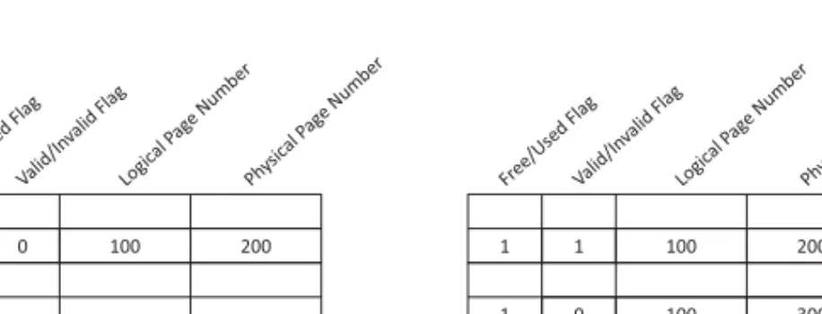
Sequential page programming. In SLC flash, pages in the same block can be programmed in any order. It should be noted that the PPN fields are not involved in the search phase;.
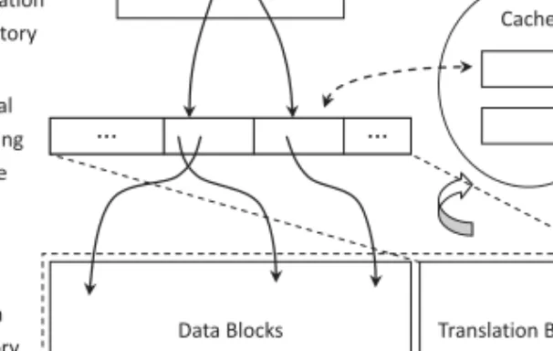
Lookup by Searching
The PPN fields are stored explicitly instead of matching the physical address of an entry (CAM lookup output) with the PPN of the data page, because if so, any fault in the CAM will prevent the corresponding page from being used. data. Furthermore, to make matters worse, each flash page corresponds to at least one CAM entry, which means that the size of the CAM is linearly proportional to that of the flash chip.
Standard NOR-Based FTL
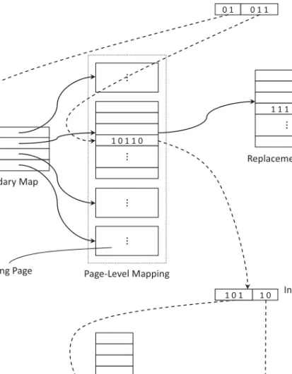
The page-level mapping table is so large that it can be accommodated in SRAM, it must be divided into pages and stored in flash memory itself. A secondary map is maintained in the SRAM, which tracks the migration of map pages at the page level.
Variable-Sized Page for NOR
A mapping table is used to track the in-block offset of pages, since their dimensions are not identical after compression. Before a block is reclaimed, all valid pages are copied to a newly assigned block, leaving the in-block offset unchanged. In this way, only one entry in the block-level mapping table needs to be changed to reflect this operation, and the page-level mapping table, including all replacement page lists, never needs to be touched.
Although this page-level FTL is quite efficient, it is not easy to implement on a NAND flash drive, since NAND can only be programmed in pages.
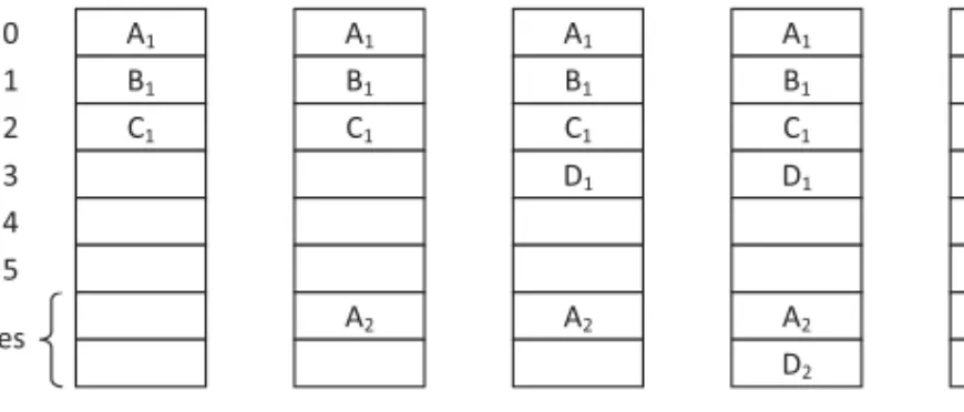
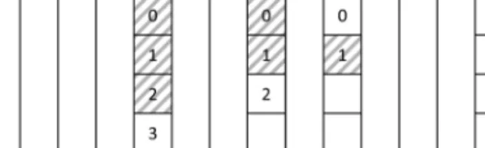
Block-Level FTL for NOR: In-Block Logging
In the example, each block consists of eight pages and the last two are used as logs. When an LPN is first written, we place it at its own offset. Obviously, the reserved pages reduce the memory's address space, since they cannot be shared between blocks and the number of reserved pages in each block must be fixed and identical; otherwise it is impossible to calculate the LBN directly from an LPN.
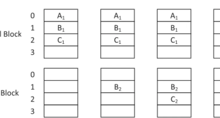
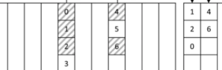
Block-Level FTL for NOR: Moving Blocks
A Two-Stage Translation Scheme
This method preselects a replacement block to which valid data in the old data block will be moved during garbage collection. In this method, an LPN is transformed to the corresponding LBN, not by simple calculation, but by looking up a table. In the example, the block with the PBN 100 is retrieved, and all valid data is moved to the PBN 200.
Acute readers may notice that this FTL is quite similar to the standard FTL described in Section 3.4, without the secondary map and the replacement page list parts. The reason we put this scheme in the block-level category is because the standard FTL sees each page as the mapping unit and reallocates any page that has been updated, whereas the conventional mapping method treats each block as the mapping unit and an updated page is against a free offset in the original block. A page allocation map is kept in each physical block, which tracks the offsets of each logical page.
Summary
BLOCK-LEVEL FTL SCHEMES
- NFTL: Log Blocks
- NFTL: Replacement Block List
- A State Transition FTL
- Summary
Each data block is assigned a replacement block list if necessary and all logical pages are kept at their own offset. After allocation, we try to keep each logical page in its own offset and the block is in M state. If the block is successfully filled, the status becomes S; otherwise the block is in N state (acts as a log block).
If all pages in the list with the desired offset have been programmed, a new block is allocated and added to the back of the list. Otherwise, the block is flipped to N state, indicating that a total reorganization is necessary during the garbage collection procedure. This newly allocated block is in M or S state depending on whether it contains free pages.
HYBRID FTL SCHEMES
- Adaptive FTL
- HFTL
- File System Aware FTL
- Summary
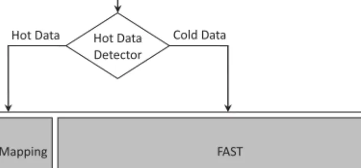
When an M-state block is filled, it is converted to an S-state block, while a full N-state block is marked invalid after copying all pages to a new block in a merge. However, a block-level FTL can hardly separate hot data from cold data if they share the same LBN. 2009] proposed a hybrid FTL scheme called HFTL (Hybrid FTL) that uses a hash-based hot data identification technique [Hsieh et al.
2006] and serves pages that contain hot data with a page-level mapping as long as they remain hot (Figure 15). The hot data identification technique is based on the Bloom filter [Bloom 1970], as shown in Figure 16. However, when the access pattern changes, some hot pages will have to be exchanged, which entails additional overhead.
LOG-BASED HYBRID FTL SCHEMES
- Block-Associative Sector Translation
- Fully Associative Sector Translation
- Superblock FTL
- Set-Associative Sector Translation
- Adaptive Set-Associative Sector Translation
- Locality-Aware Sector Translation
- K-Associative Sector Translation
- Janus FTL
- Summary
Consider the circumstances in Figure 22, where four data blocks in DBG 0 share two log blocks in LBG 0. Since the update pattern of DBG 0 is quite random, the associativity of blocks in LBG 0 can hardly be lowered. 2008] does not share log blocks between adjacent logical blocks, but directs updates to different regions of the LBA according to their access pattern.
But in the RLB, a log block can accommodate pages from any logical block such as FAST, so that the log blocks can be fully utilized. When a full merge is performed against a log block in the RLB, all data blocks that correlate with the log block will need to be reorganized. Janus FTL handles this with garbage collection in the LBA rather than merge operations.
VARIABLE-LENGTH FTL SCHEMES
- Variable FTL
- μ -FTL
- Self-Adjusting FTL
- Summary
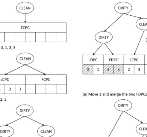
When an LCPC or LDPC is split, the newly generated internal node is marked as dirty as part of the computer has been updated and may be reclaimed. Without a consistent size of the mapping units, Variable FTL cannot implement its mapping table as a simple address array. A mapping entry is a triple that contains the starting logical address of the computer, the starting physical address of the computer, and the size of the computer in pages.
When the number of entries of a bucket exceeds a certain threshold, the bucket is full and divided into two sub-buckets according to the value of the logical starting address of the map entries. The free indicator and the exchange indicator show the head of the free zone and the tail of the exchange zone, respectively. If a lot of detailed map information is generated, some of it is exchanged in the exchange area of the corresponding segment.
PAGE-LEVEL FTL SCHEMES
Demand-Based FTL
Segments are the basic mapping unit for SAFTL, which can be very large compared to other FTL designs (eg >100MB). Variable length mapping FTLs attempt to adjust the granularity of the mapping unit according to the access pattern. Unfortunately, the address translation algorithm, the space allocation policy, the garbage collection algorithm, and the implementation of wear leveling are all complicated because the mapping units may not be aligned to block boundaries, and their sizes are not identical and keep changing.
LazyFTL
The entire mapping table is stored in flash memory, and only the referenced parts are stored in SRAM memory. An independent page-level mapping table is used for data in UBA and CBA. The most frequently accessed parts of the GMT are stored in a small LRU memory in SRAM.
To help indicate the states of pages in the CBA and the UBA, LazyFTL maintains two flags for each page—namely, the update flag and the invalid flag. Inherited from the old page during write operations if a validated one is found in the UBA or the CBA. However, if the working set is so large that the corresponding portion of the mapping table cannot be cached, performance will degrade due to frequent swap operations.
NEW CHALLENGES
No Partial Page Programming Support for MLC
Therefore, we don't try to invalidate the old page now, but wait until the map page is loaded into SRAM to update. The void flag is used to indicate whether the old page that the corresponding GMT entry points to should be invalidated. To our knowledge, page-level mapping FTLs perform better against most real-world datasets, as they can easily separate hot and cold data, have no join operations, and can be easily implemented [ Ma et al.
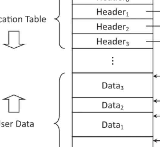
For workloads that have many consecutive updates, the mapping table can be efficiently compressed so that more requests can be served by cached parts of the mapping table [Xu et al. As a register-structured file system, YAFFS 2 treats all memory as a sequential register by assigning monotonic sequential numbers to each of the allocated blocks. To rebuild the system state from scratch, YAFFS 2 scans all the blocks to determine their sequence numbers, sorts them into memory, and scans the blocks again in reverse order.
Limited SRAM Resource
When you mount a YAFFS 2 partition, YAFFS 2 can recover the system state from a checkpoint or rebuild it by scanning all memory.
SIDE EFFECTS OF THE FTL ARCHITECTURE
- Atomicity of Write Operations
- Transaction Processing
- Multiversion Support
- Data Sanitization
- I/O Characteristics
When a page is replaced or when its log sector becomes full, the log sector is flushed to one of the log sectors in the same block where the data page resides. If one wants to improve the security of deleting a single file, one will need the help of FTL, which owns all the address information when a file is updated [Wei et al. In Proceedings of the 5th IEEE/ACM International Conference on Hardware/Program Code and Systems Synthesis.
InProceedings of the 14th International Conference on Architectural Support for Programming Languages and Operating Systems. InProceedings of the 8th IEEE/ACM/IFIP International Conference on Hardware/Software Codesign and System Synthesis. InProceedings of the ACM SIGPLAN/SIGBED 2010 Conference on Languages, Compilers and Tools for Embedded Systems.