JAMES AMBROSE Former Professor of Architecture, University of Southern California Los Angeles, California based on work. This publication is intended to provide accurate and reliable information regarding the subject matter.
PREFACE TO THE SIXTH EDITION
More important to the research here than mechanical mathematical operations is the conceptual visualization of the work being performed. Mastering the work in this book is essentially preparatory in nature and leads to a next step developing the topic of structural design.
PREFACE TO THE FIRST EDITION
One of the most important features of this book is a detailed explanation of the many illustrative examples. This book does not present shortcuts to the basic principles of mechanics and strength of materials.
INTRODUCTION
First, internal forces that resist the actions of the external forces are set up in the body. For some of the work in this book, the units of measurement are not meaningful.
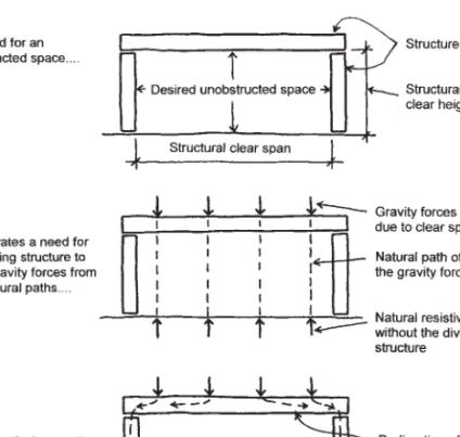
STRUCTURES: PURPOSE AND FUNCTION
LOADS
Calculation: As pressure, depending on the extent of the explosion and its proximity to the structure. Forces can be exerted on elements of the structure during production, transportation, erection, storage, and so on.
SPECIAL CONSIDERATIONS FOR LOADS
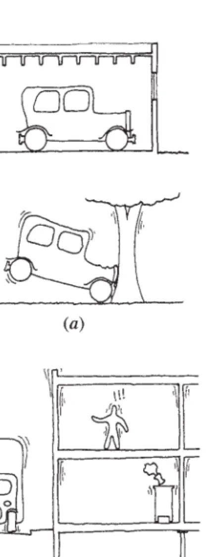
In addition to earthquake effects, vibrations of the structure can also be caused by heavy machinery, moving vehicles or high-intensity noises. In the example just quoted, the effect of the force on the function of the structure was described.
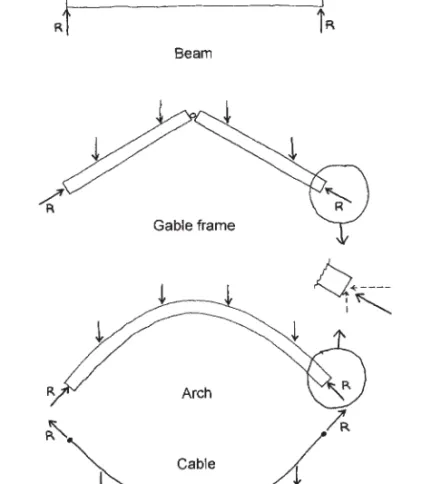
GENERATION OF STRUCTURES
The floor function typically dictates the need for a flat, horizontal geometry; thus, most floor structures belong to the flat span category (no arches, overhead wires, etc.). Most floor structures have a relatively short span due to the high loads and the inefficiency of the planar span structure.
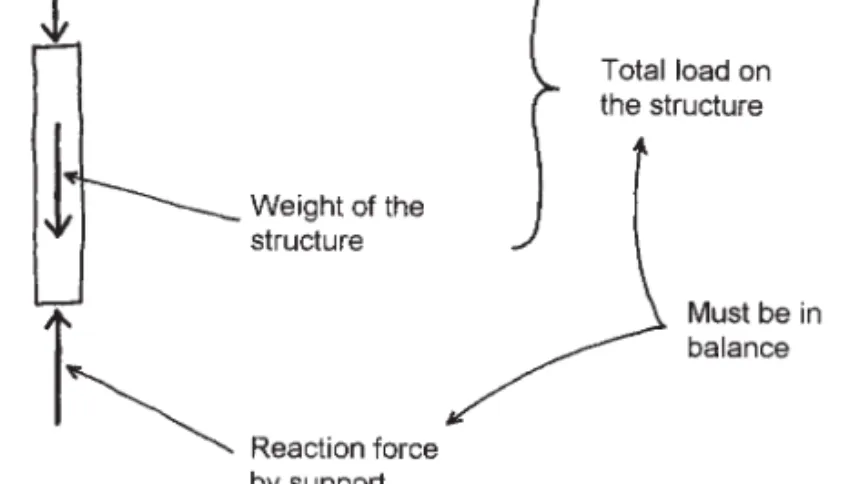
REACTIONS
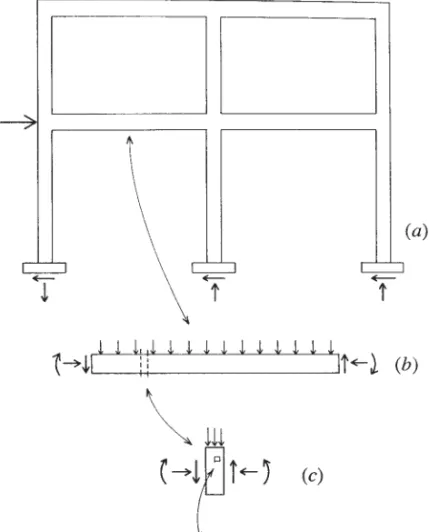
The total support reaction for the cantilever thus consists of a combination of the vertical force (Rv) and the resistance moment (Rm). For the rigid frame shown in Figure 1.13, there are three possible components of the reactions.
INTERNAL FORCES
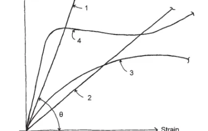
Wood, on the other hand, has different strengths depending on the direction of tension in relation to the wood fiber. The relative magnitude of these changes determines the quality of the structure called stiffness or stiffness.

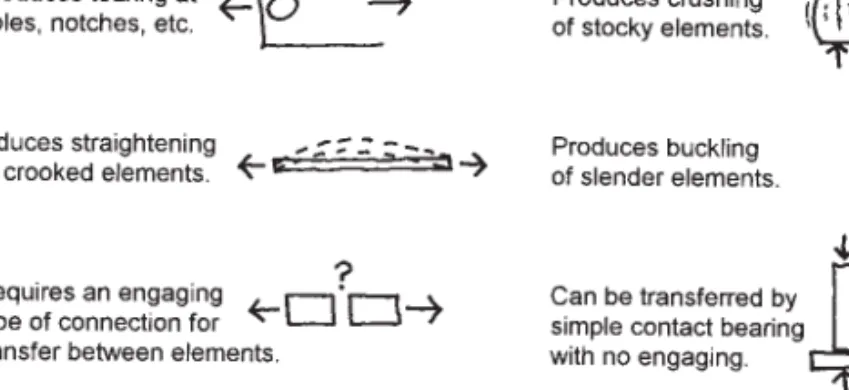
TYPES OF INTERNAL FORCE
As shown in Figure 1.29, the internal force acting in the beam is a combination of bending and shear. In the columns of the frame shown in the lower part of Figure 1.32, the load on the beam will produce a combination of compression, bending and shear.
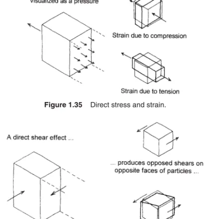
STRESS AND STRAIN
As shown in Figure 1.35, direct compressive stress in a single direction results in shear stress in the material in that direction. What can be combined is direct stress due to bending and direct diagonal stress due to shear, as shown in Figure 1.41b. This is the combination of direct shear stress and diagonal shear stress due to direct stress.
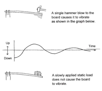
DYNAMIC EFFECTS
The elapsed time for one full cycle of this proposal is the basic term of the board. If the boy jumps on the end of the board with a certain rhythm, he can cause an extreme up and down movement of the board. He can also find the exact variation in his bouncing that will result in an almost complete, instant stoppage of the board's motion.
DESIGN FOR STRUCTURAL RESPONSE
Observing the shape of these interactions is an essential first step in a complete investigation of this beam. Finally, in Figure 1.54 a small particle of the material of the beam is shown, on which the external effects are those of the adjacent particles. The overall shape of lateral deflection of the bent and the character of bending in each member can be visualized from this figure.
LOADS AND RESISTANCE
The previous chapter gave an overview of the world of structural analysis as an activity supporting the design of building structures. This chapter begins with a more deliberate study of the basic applications of physics and mathematics to the real work of structural analysis. In the following work, they are also used as part of the clarification of the ideas and the steps for analysis procedures.
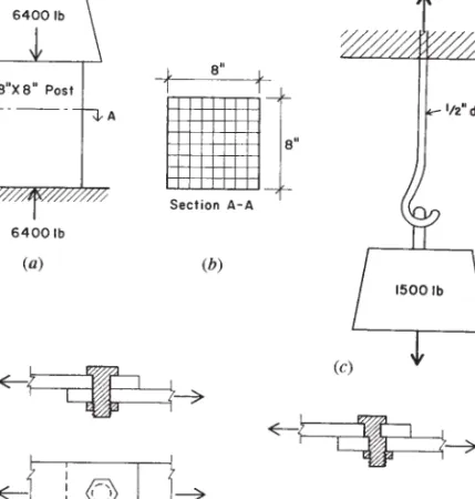
FORCES AND STRESSES
Thus, the wooden post is affected by a series of balanced forces consisting of the applied (or active) downward load of 6400 lb and the resistive (reactive) upward force of 6400 lb. To avoid being crushed, Wooden piles develop an internal compressive force due to stress in the material, stress being defined as the internal force per unit area of the cross-section of the pile. For the situation shown, every square centimeter of the cross-section of the pile must develop a stress equal to lb/sq.
TYPES OF FORCES
VECTORS
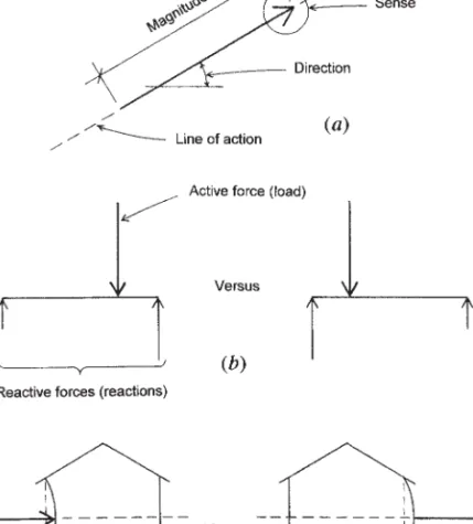
Direction of a force: This refers to the direction of its path, which is called its line of action. To a certain extent, the length of the arrow represents the magnitude of the force. In the case of a beam, the displacement of the point of load (active force) affects the changes in the forces on the beams (reactions).
MOTION
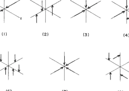
It is necessary to qualify a set of forces in the manner just illustrated before proceeding with an analysis, whether carried out algebraically or graphically. When a system of forces acting on an object produces no motion, the system of forces is said to be in static equilibrium. If the lines of action of a force system have a point in common, the forces are simultaneous.
FORCE COMPONENTS AND COMBINATIONS
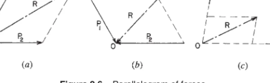
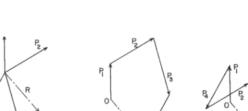
Note that the resultant of the forces P1 and P2 shown in Figure 2.6bisR; its direction is towards the common point. We construct a parallelogram of forces and find that the resultant of the force is about 115 lb, its direction is upward to the right, and its line of action passes through the common point of the two given forces. Let it be necessary to find the resultant of the simultaneous forces P1, P2, P3 and P4 shown in Figure 2.9.
GRAPHICAL ANALYSIS OF FORCES Force Polygon
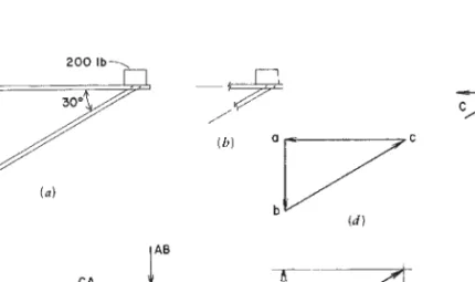
The action line of the resultant of the given system, shown in Figure 2-12, has an action line passing through the common point, its magnitude and direction found in the force polygon. When a force is represented by a line in the force polygon, a letter is placed at each end of the line. It is clear that the force in the rope AB is 100 lb, but the magnitude of the forces in the ropes BC and CA are unknown.
INVESTIGATION OF FORCE ACTIONS
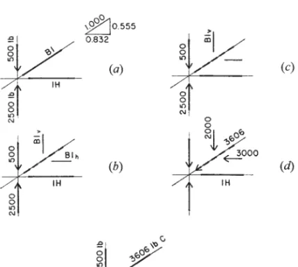
Find the significance (tension or compression) and magnitude of the internal forces in the elements indicated by question marks in Figure 2.15a–d using graphical methods. The sense of the forces can be determined by following the sequence of the force flow on the polygon: from atobtoctoa. To obtain the value for BC, consider the relationship between the force and its components, as shown in Figure 2.16f.
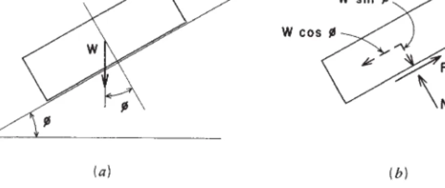
FRICTION
The coefficient of static friction (before movement occurs) is greater than the coefficient of kinetic friction (during actual sliding). Find the horizontal force P required to slide a 100-lb block if the coefficient of static friction is 0.30 (see Figure 2.20). If the block weighs 15 lb and the coefficient of static friction is 0.40, will the block slide.
MOMENTS
A torque can be increased by increasing the magnitude of the force or by increasing the distance of the torque arm. A free-body diagram of the pier under the action of these three forces is shown in Figure 2.27b. As with the wheel in the previous illustration, a scaled layout can be used to determine the magnitude of the thrust force.

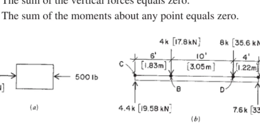
FORCES ON A BEAM
Write the two equations for moments for the four forces in Figure 2-30b, taking the CandDa points as centers of moments, to verify the equilibrium of the system. Figure 2.32 shows a single-span beam with two supports, one at each end of the beam. The simple beam, shown in Figure 2.35, has a single concentrated load and an evenly distributed load over part of the span.
ANALYSIS OF TRUSSES
GRAPHICAL ANALYSIS OF TRUSSES
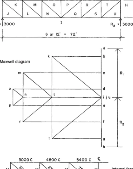
The letters on the space diagram identify individual forces at the truss joints, as discussed in Section 2.8. The force polygon for this link, as shown on the Maxwell diagram, is read as ABIHA. AB represents the load, BI the force in the upper chord member, IH. Solving for a single unknown point on the Maxwell diagram is equivalent to finding two unknown forces at a joint, since each letter on the space diagram is used twice in the force identification for the internal forces.
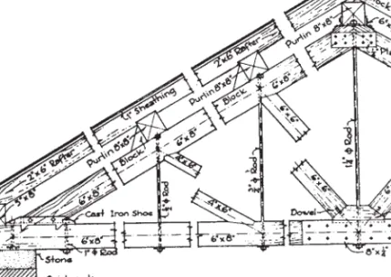
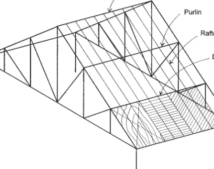
ALGEBRAIC ANALYSIS OF TRUSSES
If so, the forces and their components will be as shown in Figure 3.8c. The most direct way is to display them on a scale diagram of the hood, as shown in Figure 3.9a. When solving the algebraic method of joints, the results can be recorded on a separated joint diagram, as shown in Figure 3.9b.
THE METHOD OF SECTIONS
The free-body diagram of the portion of the truss to the left of this cut plane is shown in Figure 3.11a. The method of sections is sometimes useful when it is desired to find the internal force in individual members of a truss without performing a complete analysis for all the members. Find the internal forces in the rafters in Figure 3.13 using: (1) a Maxwell diagram; (2) the algebraic method of sections.
ANALYSIS OF BEAMS
TYPES OF BEAMS
In general, there are five types of beams, which are identified by the number, type and position of supports. By simply resting the beams on a support at each end, the ends of the beam are free to rotate (Figure 4.2a). A beam embedded in a wall and projecting beyond the face of the wall is a typical example (Figure 4.2b).
LOADS AND REACTIONS
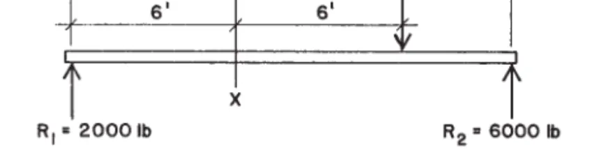
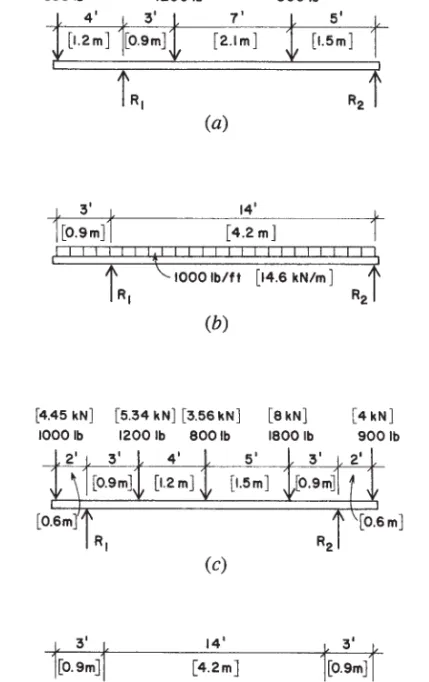
However, some uniformly distributed loads supported by the beam may span only part of the beam's length. However, for a uniformly distributed load, the load can also be expressed as a unit load per unit length of the beam. For the beam in Figure 4.3, the load is placed symmetrically and so the two reactions will each be half the total load.
SHEAR IN BEAMS
From this procedure it follows that the maximum shear value for simple beams is equal to the largest reaction. Consider next the value of the vertical cut Vat an infinitesimally short distance to the right of R1. Applying the rule that the shear is equal to the reaction minus the loads to the left of the section, we write
BENDING MOMENTS IN BEAMS
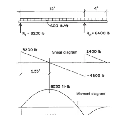
It is called the bending moment (or internal bending moment) because it is the moment of the forces that create bending stresses in the beam. The bending moment is the algebraic sum of the moments of the forces on both sides of the cross-section. For the parts of the beam on which a uniformly distributed load occurs, the shear diagram consists of straight oblique lines.
SENSE OF BENDING IN BEAMS
For the location of the zero intercept point, considering its distance from the left support as x,. The location of the zero moment point can also be determined by writing an equation for the sum of the moments at the unknown location. Note that the shear goes from zero at the 4,000-lb load location and at both supports.
CANTILEVER BEAMS
Draw the shear and bending moment diagrams for the beams in Fig. 4.15, giving all critical values for the shear and bending moments and all important dimensions. Draw the shear and bending moment diagrams for the cantilever beam shown in Fig. 4.16b carrying a uniformly distributed load of 500 lb/ft along its entire length. Draw the shear and bending moment diagrams for the beams in Fig. 4.18, giving all critical values for the shear and bending moments and all important dimensions.
TABULATED VALUES FOR BEAM BEHAVIOR Bending Moment Formulas
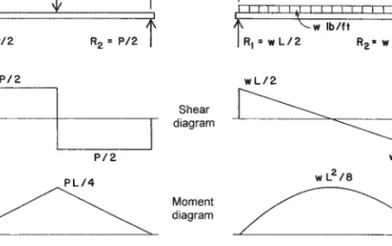
Therefore, the maximum bending moment occurs at the center of the span, under the load. Solution: As just derived, the formula that gives the value of the maximum bending moment for this condition is M=PL/ 4. Solution: As just derived, the formula that gives the maximum bending moment for a simple beam with uniformly distributed load is M = wL2/8.
CONTINUOUS AND RESTRAINED BEAMS
BENDING MOMENTS FOR CONTINUOUS BEAMS It is beyond the scope of this book to give a detailed discussion of bend-
Calculate the values for the reactions and construct the shear and moment diagrams for the beam shown in Figure 5.4a. However, using the equation for this moment at the middle support yields a condition that can be used, as shown in the following work. Calculate the reactions and construct the shear and moment diagrams for the beam in Figure 5.7a.
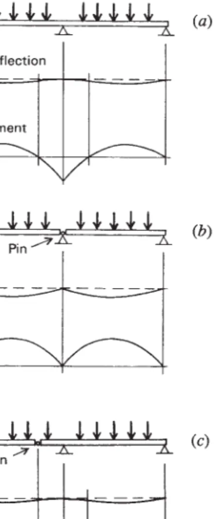
BEAMS WITH INTERNAL PINS
Solution: Because of the internal pin, the first 12 feet of the left side span act as a simple beam. The second section of the beam is statically determined, and its reactions can now be determined by static equations. As previously mentioned, the pin in this example is located exactly at the bending point of the continuous beam.
APPROXIMATE ANALYSIS OF CONTINUOUS BEAMS In some situations, it may be acceptable to perform an approximate
RETAINING WALLS
HORIZONTAL EARTH PRESSURE