Achieving 100% internal quantum efficiency by completely harvesting the light can be achieved with the use of phosphorescent dopants. In this work, the optimization of OLED devices has been studied using different exciplex systems mixed with a novel synthesized phosphorescent dopant. The yellow and red phosphorescent dopant was synthesized by Tamkang University, Taiwan, using three kinds of dopants (Y1, R1 and R2).
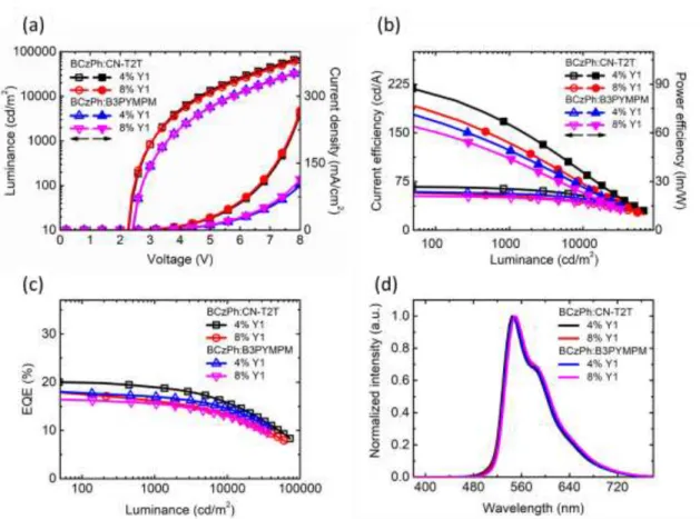
In yellow phosphorescent OLED with BCzPh system, the best exciplex system was shown by BCzPh:CN-T2T:4% Y1 with a maximum external quantum efficiency of 20.02% with a maximum luminance of 72,640 cd m-2 at +8 V applied bias. For the red phosphorescent OLED, the devices show low electroluminescence compared to other works, which require further study of the red phosphorescent dopant.
Introduction
Overview
The other way is to improve the performance of the device by changing the structure of phosphorescent dopants. In the commercial market, the good electroluminescent performance of iridium-based yellow phosphorescent dopants is not too many choices. As a result of the lack of commercial opportunities for yellow dopants, many researchers are trying to synthesize new iridium-based yellow phosphorescent dopants as an alternative way.[26-31] For example, Mei et al.
Unlike yellow phosphorescent dopants, many red phosphorescent dopants are readily available on the commercial market. In this study, the use of the exciplex system as a co-host for new phosphorescent dopants is studied.
Objectives
Outline
This chapter will describe the steps of the experimental procedure, the material used and the measurement setup. In this part, the proposal and the future plan of this part will also be written.
Literature Review
- Organic Light Emitting Diode
- Basic Structure and Principle of OLED
- Exciplex Formation
- Exciplex Forming Co-host for Phosphorescent Dopant
- Photoluminescence Measurement
- Impedance Spectroscopy Measurement
- Capacitance-Voltage Plot
- Impedance Cole-cole (Z-Plot)
- Transient Electroluminescene Measurement
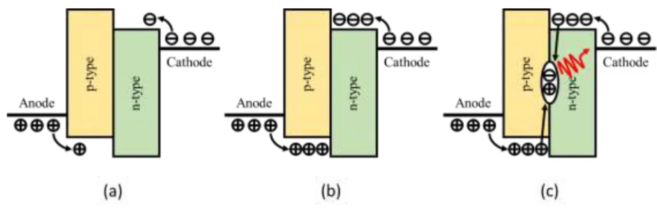
The charge injection mechanism can be induced in two, which are Richardson-Schottky thermionic emission and Fowler-Nordheim (FN) tunneling injection.[37] The illustration of charge injection is shown in Figure 2.4(a). Based on the evolution, exciplex formation can be separated into two methods; interface system and bulk system.[41] The differences of interfacial system and bulk system can be shown in Figure 2.7(a) and Figure 2.7(b) respectively. As is the case in Figure 2.8, the emission spectrum of the OLED devices will not overlap with the emission spectrum of the exciplex host due to the lower triplet states of the dopant than the exciplex host.
In Figure 2.9, the C1 is an optical chopper at the normal position, the C2 is an optical chopper for PL decay measurement, the BPF is a band-pass filter, the LPF is a long-pass filter, the NDF is a neutral density filter, and the computer is a personal computer. In the OLED research field, the PL spectra are used to detect the emission spectrum for each emitting material (singlet or exciplex materials, fluorescence or phosphorescence materials, etc.).[15–17] In addition, the PL spectra can be used to analyzed a degradation mechanism for the release of materials.[15] The TRPL results are used to see the TADF phenomenon in the exciplex host system and the energy transfer quality from a host to a doping system.[16]. The examples of PL spectra and TRPL results are shown in Figure 2.10(a) and Figure 2.10(b), respectively.
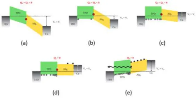
The illustration of the movement of electrons and holes under different applied biases as shown in Figure 2.12 helps us analyze a capacitance-voltage plot from an impedance measurement.
![Figure 2.1 First practical OLED by Tang et al.[1]](https://thumb-ap.123doks.com/thumbv2/123dok/10245618.0/18.893.167.776.196.559/figure-practical-oled-tang-et-al.webp)
Experimental Procedure
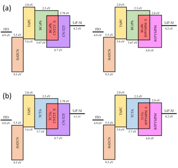
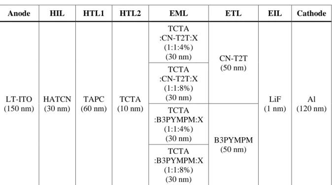
- OLEDs Structure
- OLEDs Materials
- OLEDs Fabrication
- Substrate Preparation
- Material Preparation
- Material Deposition
- Device Encapsulation
- OLEDs Measurement
- Device Performance Characterization
- Photophysical Characterization
- Electrical Characterization
Indium tin oxide (ITO) was used as the anode in the OLED structure with a resistance of 15 Ω □-1. The exciplex in the emission layer of OLED using BCzPh as an electron donor host material. The explanation of each step in OLED manufacturing will be explained in more detail in the next sub-chapter.
The large ITO substrate is cut to 100 × 100 mm and patterned with a laser cutter, as shown in Figure 3.9(a). After the sublimation process, the cleaned material should be placed in a material holder for use in the chamber. There are three types of material carriers, which are organic tubes, organic boats and metal boats, as shown in Figure 3.11.
All the material used in this study was placed in the thermal evaporation chamber in the appropriate positions as shown in Figure 3.12(a). A clean ITO substrate was placed in the chamber using a holder commonly referred to as an organic mask, as shown in Fig. 3.12(b). The respective thickness of each material used in this study was calibrated using a surface profilometer (Dektak XT) from Bruker as shown in Figure 3.13.
The temperature sensors for each source were displayed in the control box, as shown in Figure 3.14(b). The encapsulation glass was placed in the holder and the edge of the glass remained. The model of a spectrophotometer and the source meter used in this study are Photo Research PR-655 and Keithley Instrument Model-2400, as shown in Figure 3.18(a) and Figure 3.18(b), respectively.
All measurements for impedance spectroscopy were achieved at room temperature. The data from this measurement is an electroluminescence spectrum, then must be plotted for analysis in OriginPro software.
Result and Discussion
Optimization of Yellow Phosphorescent OLED
- Device Performance Characterization
- Photophysical Characterization
- Electrical Characterization
- Transient Electroluminescence Characterization
This result indicates that the BCzPh device doped with CN-T2T has a higher charge balance than the B3PYMPM device due to the higher electron mobility of the acceptor. Comparing with other works on synthesized yellow phosphorescent dopant, the turn-on voltage of our work is the lowest. [26,31] The lower turn-on voltage of this work is due to the use of an exciplex host system. to improve the charge balance within the EML layer. As previously explained, the higher current density of BCzPh with CN-T2T devices is due to higher mobility and charge balance [57,58] The higher mobility will cause electrons and holes to flow more easily within the materials.
It is shown that the emission peak for all devices appears almost at the same wavelength peak around 545-550 nm. The result of the EL spectrum shows a similar trend for all unit structures, indicating that all the energy was transferred to the phosphorescent dopant. An effect of increasing the dopant concentration can also be seen in the improvement of the current density of the devices, as shown in Figure 4.2(a). This result explicitly indicates that the exciplex was formed in the devices.[16,41] The PL spectra of exciplex-host mixed Y1 doping with different doping concentrations were also observed, as shown in Figure 4.3(a).
The results show that all PL spectra have a single peak around 445–450 nm, which is very different from the host exciplex peaks, explaining that all energy was transferred and the PL emission is only from the dopant.[16] The higher doping concentration effects were also seen in PL spectral emission. The new PL emission with absence of a single component emission is a good indication of exciplex formation during photoexcitation.[16] The PL spectra for the exciplex host mixed with Y1 dopant are shown in Figure 4.4(b). The prompt profile for the TCTA exciplex host mixed with Y1 dopant does not appear in the TRPL response.
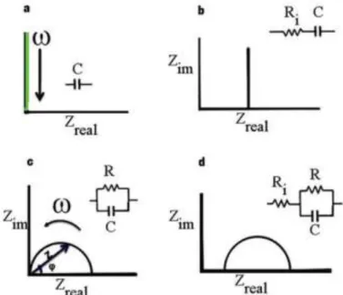
This result shows that the energy has been completely transferred to the phosphorescent dopant.[16] The TRPL lifetime of the TCTA exciplex system mixed with 4% and 8% Y1 dopant is summarized in Table 4.3. All devices were equipped with an equivalent RC circuit, as shown in Figure 2.15. The TREL result for BCzPh devices was shown in Figure 4.9(a) and Figure 4.9(b) for the decay portion.
This is because the charge is injected into the devices with a high doping concentration, which could degenerate through the self-quenching process, so it will slow down the generation of light. [59,60] A small overshoot of the peak was observed even a few microseconds after turning off the bias. . As shown in Figure 4.9(b), the observed short decay time value was around 6–7 µs for all devices, indicating a low trap density in the devices.
Optimization of Red Phosphorescent OLED
- Device Performance Characterization
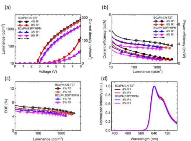
The EL characteristic data of BCzPh as a donor material for red phosphorescent (R1) OLED devices were summarized in Table 4.7. The EL characteristic data for TCTA as a donor material for red phosphorescent (R2) OLED devices were summarized in Table 4.8. The efficiency roll-off for all units is also high enough at around 20% at a luminance of 1,000 cd m-2.
In summary of the red PhOLED, the performance of all devices with a new red phosphorescent dopant R1 and R2 generates unsatisfactory performance. Because the basic structure of the exciplex system as a co-host works very well in the yellow dopant with superior EL performance. Thus, the synthesized red phosphorescent dopant should be studied more to improve the EL performance in the future.
Conclusion
Thompson, Achieving full-color organic light-emitting devices for lightweight flat-panel displays, IEEE Trans. Wong, Exciplex-Forming Cohost for High-Efficiency and High-Stability Organic Phosphorescent Light-Emitting Diodes, ACS Appl. Wong, Versatile Co-Host Exciplex Formation for Improving Efficiency and Lifetime of Organic Fluorescent and Phosphorescent Light Emitting Diodes, ACS Appl.
Lee, Phthalonitrile based charge transfer type host for yellow phosphorescent organic light emitting diodes, Org. Huang, A yellow-emitting homoleptic iridium(III) complex constructed from a multifunctional spiroligand for high-efficiency phosphorescent organic light-emitting diodes, Inorg. Wong, Novel iridium(III) complexes bearing dimesitylboron groups with near 100% phosphorescent quantum yields for high-efficiency organic light-emitting diodes, J.
Fujikake, Highly efficient and stable red phosphorescent organic light-emitting diodes using platinum complexes, Adv. Niu, Saturated Red Phosphorescent Iridium(III) Complexes Containing Phenylquinoline Ligands for Efficient Organic Light Emitting Diodes, Dye. Cao, Analysis of Intrinsic Degradation Mechanism in Organic Light Emitting Diodes by Impedance Spectroscopy, Chinese Phys.
Jung, Impedance spectroscopy analysis of organic light-emitting diodes fabricated on plasma-treated indium-tin-oxide surfaces, J. Kim, Equivalent circuit models in organic light-emitting diodes designed using a cole-cole plot, Mol. Lee, Elucidation of the crucial role of the hole injection layer in the degradation of organic light-emitting diodes, ACS Appl.
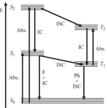
![Figure 2.6 The emission process of the exciplex formation system.[37]](https://thumb-ap.123doks.com/thumbv2/123dok/10245618.0/24.893.208.717.765.1044/figure-emission-process-exciplex-formation.webp)
![Figure 2.8 The exciplex system as a co-host for phosphorescent dopant.[11]](https://thumb-ap.123doks.com/thumbv2/123dok/10245618.0/26.893.216.715.818.1102/figure-exciplex-host-phosphorescent-dopant.webp)
![Figure 2.11 The capacitance-voltage (CV).[43]](https://thumb-ap.123doks.com/thumbv2/123dok/10245618.0/29.893.310.620.560.898/figure-the-capacitance-voltage-cv.webp)
![Figure 2.16 The voltage pulse characteristic and TREL measurement response of OLED devices.[55]](https://thumb-ap.123doks.com/thumbv2/123dok/10245618.0/34.893.288.662.262.706/figure-voltage-pulse-characteristic-trel-measurement-response-devices.webp)