The Invention and Development of the Radiosonde, with a Catalog of Upper Atmospheric Telemetering Probes in the National Museum of American History, Smithsonian Institution. The invention and development of the radiosonde : with a catalog of upper atmospheric telemetry probes in the National Museum of American History, Smithsonian Institution / John L. Furthermore, the chronological portion of the radiosonde's history which is the focus of this monograph (1929 to 1940) is particularly important because it was during those years that the basic design features of radiosondes developed, and because these developments laid the foundation for the introduction in the 1940s of multichannel radio transmission via subcarrier modulation (the basis for all modern an - alog radiotelemetry systems).
The reason for this publication is the presence of a substantial collection of significant examples of the radiosonde in the National Museum of American History (NMAH), Smithsonian Institution. The following sections outline the historical development of the radiosonde from its invention to the present. Finally, there is a catalog of the radiosondes in the collection of the National Museum of American History, Smithsonian Institution.
WmL> 1 pffa
Preradio Telemetering, 1842-1894
The development of the electromagnetic telegraph advanced rapidly after about 1830, and by 1840 many miles of circuits had been built. There were various schemes for representing the alphabet and numbers, such as the Morse-Vail alphabet, but these were only translations of the original symbols. The slight difference in the natural period did not affect the mean period of the receiving pendulum because synchronization was re-established every cycle.
Particularly impressive was a system derived from Chappe's time coding, which removed much of the burden from the operator for the correct interpretation of telegraphic symbols. The accuracy of analog data, on the other hand, is closely related to the parameters of the transmission system. The transmission was "digital" and the accuracy was thus independent of the uniformity of the drum's rotational speed (although it was limited by the number of guide rods incorporated in the drum).

Radio Telemetry, 1895-1929
When Marconi applied similar tuning to the antenna circuit of a receiver, the overall effect was dramatic. After 1915, the demands of the military services fighting in the First World War gave impetus to the development of more efficient tubes and circuits. From a Marconi Instrument Company advertising brochure mailed to the electronics industry in the spring of 1987.).
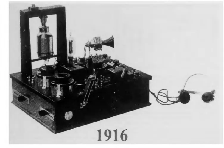
One side of this widely tuned circuit was connected to the dragon's steel tether. Idrac greatly improved reception by using a parallel tuned circuit coupled inductively to the ground tether. This circuit, a plate-tuned triode oscillator with inductively coupled feedback to the grid, was used in the earliest regenerative receivers (Figure 17).
RADIO APPARATUS
This circuit, which is largely unchanged, and a Hartley circuit in which the grid is tapped by the plate coil, later became standard radiosonde transmitters.
Amateur and Experimental Use
Radio foi* Corporation
The Early Years, 1921-1928
He had noted that the characteristics of the radio transmitter changed due to the effects of temperature and other meteorological conditions. The secondary of the transformer stepped up the primary voltage to supply about 200 volts to the tube plate. The oscillator plate coil was in the center of the antenna, which formed a center-fed dipole with a total length of 25 meters.
In fact, the radiosonde was described earlier in this publication as a "natural" extension of the balloon probe. Towards the end of the nineteenth century, improvements in the design of kites and balloons made it possible to obtain data from the upper altitudes on a more frequent basis. In the first decades of the twentieth century, improvements in weather science were due in part to advances in theory and in part to the increasingly intensive exploration of the upper atmosphere.
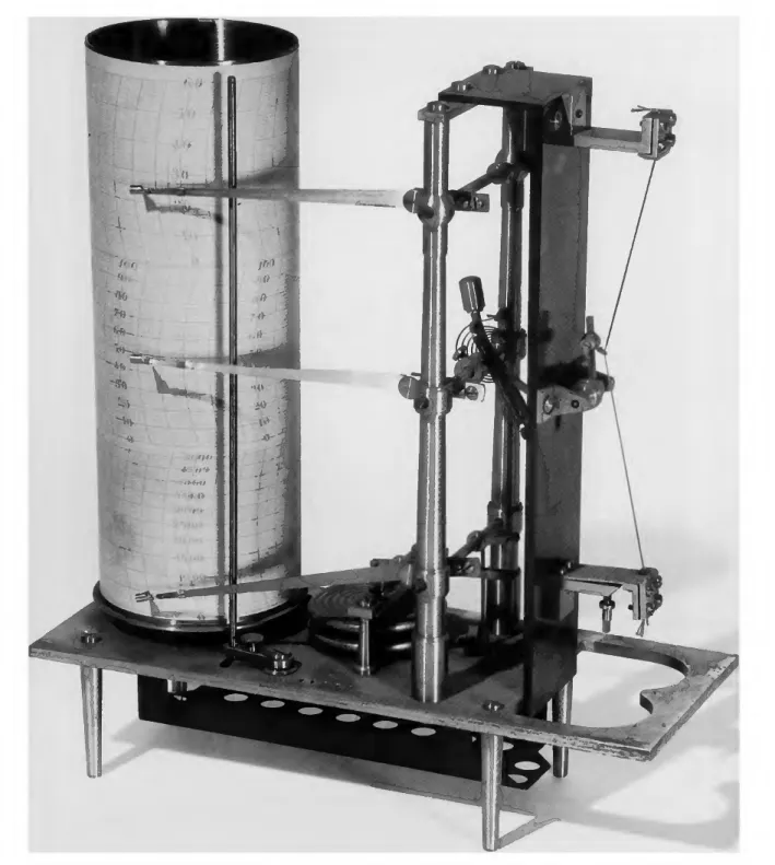
From left to right: the windmill and gear for modulation, the half-metal, semi-insulating cylinder, the gear with the on-off key cam (that is, the metal spindle parallel to the cylinder), the arm of the thermometer, and the bimetallic thermometer itself. Changes in the electrical properties of such components with variation of the measured atmospheric parameter, in turn, changed the radio signal, usually through a change in frequency. The missing tenth tooth in the wheel caused a gap in the small frequency modulations, indicating a complete revolution of the cylinder.
The thermometer arm is at the bottom of the cylinder and the barometer arm is at the top. According to Beelitz, Moltchanoff also stated that this flight was "the first in the world where a radiosonde was used to study the atmosphere." this. The Morse code captured by the receiver clearly indicated which comb was in contact with the temperature arm.
Pressure was measured by means of a Bourdon tube and indicated by signal breaks.

Maturity, 1931-1940
QfrO^QfrOg-
On the ground, the signals were picked up by a conventional receiver connected to a rotary cylinder type facsimile recorder. The hair hygrometer moved an arm which, in conjunction with a fixed contact, turned off the transmitter once per revolution for a period of time indicating humidity. Contact arms from a bimetallic thermometer, aneroid barometer, and hair hygrometer touched the conductive parts of the rotating cylinder in a way that produced a combination of two Morse codes for each sensor.
The Duckert radiosonde underwent various modifications during the 1930s (Duckert, including replacing the oil-filled variable capacitor used as a temperature sensor with an "electric" thermometer consisting of a temperature-sensitive capacitor. Revised Duckert designs probes were mass-produced by the German company Telefunken in the 1930s.Since the natural frequency of the spring was 1500 oscillations per minute, the motor shaft rotated at 1500 revolutions per minute with great constancy, reducing this source of inaccuracy.
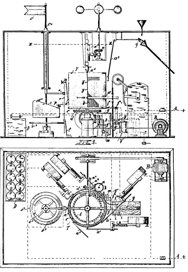
The frame of the probe was insulated from the rotating spiral contact and supported an aneroid barometer (E), a bimetallic thermometer (F) and the gold beater's skin hygrometer (G). The contact arms of each sensor moved over a spiral so that the end of the spiral touched reference points H and J once in each revolution. Because each of the three sensors required a separate oscillator, it was heavy, a defect magnified by the fact that the method for “read-.
Two of the capacitances were of fixed type and were used as reference, and the other three were variable according to the sensor output (see Figure 44). During each switch cycle, two reference capacitors were connected in an oscillator circuit as a means of eliminating errors caused by frequency shifts. Note that the symmetrical half-wave antenna required the probe to be centered between each half of the antenna.
Another factor that influenced the retention of the original designs was that by 1940 the representative probes in each category were "good enough".11 This fact, plus the added cost.

SCALE
The Radiosonde after 1940
Earlier research also demonstrated the radiosonde's utility for a variety of geophysical applications, which we discuss in this section. On the other hand, the situation was different in the case of research radiosondes, where the objectives included the measurement of ozone, cosmic rays, etc., and involved taking advantage of the dramatic advances in balloon technology in the 1940s. This method was similar to that used in the Duckert probe described in the previous section.
In the United States, the NBS-Navy probe was adopted by the Weather Bureau, but during the early 1940s the antenna at 1680 MHz was small enough to be self-contained in the radiosonde package. In the late 1950s and 1960s additional models appeared with changes in mechanical construction, such as the AN/.
At the beginning of the 1940s, another factor, interference, began to affect the operating frequency of radiosondes. The development of the radiosonde with frequency modulation of the sound carrier was important for the development of data telemetry. In the 1940s, the introduction of multi-channel radio telemetry enabled the simultaneous transmission of output data from many sensors.
Also, the development of multichannel radio telemetry was accelerated in the immediate postwar years by the needs of military missile programs. At the time, the question of whether "primary" cosmic rays (that is, the component of such radiation that exists outside Earth's atmosphere) were electromagnetic waves or charged particles was still unresolved. Johnson's probe (discussed in the previous section) was designed to measure cosmic rays.
In the late 1930s, Jean Piccard conducted additional research on cellophane balloons at the University of Minnesota.

Conclusion
Identified by the donor as a Vaisala type, it was improved by Schulze at the "Marine Observatorium" in Griefswald (Germany) in 1942-1944. Protruding above is the housing housing the sensor elements for measuring pressure (aneroid) and humidity (golden skin)—the temperature element is missing (but see cat. no. 319830). Early investigators were aware of the potential advantages of shorter wavelengths, but faced considerable technological obstacles to the use of short waves.
The first production models of the NBS radiosonde were standardized in the 4-meter range because that wavelength was low enough to achieve almost all the advantages possible in smaller size and weight. However, it did not place the radiosonde signals in a suitable part of the radio band to solve all the problems. Because these problems seemed insoluble within the limitations of the mechanical approach, research into electrical sensors in the.
There is little published data on the in-flight accuracy of production versions of various radiosonde models. Manuscripts intended for serial publication undergo a thorough review (conducted by their originating museums or Smithsonian offices) and are submitted to the Smithsonian Institution Press on Form SI-36, which must demonstrate approval by the appropriate authority designated by the sponsoring organizational unit. Requests for special treatment - use of colors, folds, bound covers, etc. - request additional approval from the sponsoring authority on the same form.
Synonymy in zoology must use the short form (taxon, author, year), with full citation at the end of the paper under. Extensive notes should be collected together and placed at the end of the text in the notes section. For titles of books and articles, use sentence-style capitalization according to the rules of the language used (exception: capitalize all main words in English).
Legends for illustrations should be submitted at the end of the manuscript, with as many legends typed, double-spaced, on a page as is convenient.