A thesis Presented to The Faculty of Alfred University
Investigating the Structure, Solubility, and Antibacterial Efficacy of Silver and Copper Doped Hydroxyapatite
by
Katie M. Weiss
In Partial Fulfillment of The Requirements for
The Alfred University Honors Program April 2017
Under Supervision of:
Chair: Dr. Anthony W. Wren, Assistant Professor of Biomaterials Engineering
Committee Members:
Dr. Alexis G. Clare, Professor of Glass Engineering Science
Dr. S.K. Sundaram, Professor of Materials Science and Engineering
ii
ACKNOWLEDGMENTS
Firstly, I would like to express my sincere gratitude towards my advisor, Dr. Wren for his continuous support during research for thesis, past research projects, and in class. His door is always open and he has always made time to guide me in my research while also constantly pushing me to achieve to my fullest potential. I would like to thank Dr. Tim Keenan for always being available for additional help and serving as a wealth of knowledge in the lab. I also want to thank my committee members Dr. Clare and Dr.
Sundaram for challenging me with new ideas and questions regarding my research. My sincere thanks go out to Sahar Mokhtari who has spent countless hour in the lab with me running samples, offering suggestions, and helping me develop my skills. Thank you to my friends for forcing me to take breaks so I didn’t drive myself insane with all the work and the ßM∑∫ squad for moral support. Last but not least, I would like to thank my family and my wonderful fiancé Scott. They have always been so supportive of me in everything I do and pick me back up when I feel like giving up. My parents have continuously expressed the importance of education from supplying me with an endless supply of books as a child and stimulating my mind with memory games and puzzles. From as long as I can remember, I’ve always looked up to my big sig sister, Kristen. Her love for science and medical research is what inspired me to pursue my degree and continues to drive me in all my work and research.
TABLE OF CONTENTS
Page
Acknowledgments ... ii
Table of Contents ... iii
List of Tables ... v
List of Figures ... vi
Abstract ... viii
INTRODUCTION... 1
A. Bone ... 1
1. Importance of the Skeletal System ...1
2. Types of Bone ...1
(a) Types of Bone Cells ... 2
(b) New Bone Formation ... 3
B. Hydroxyapatite (HA) ... 4
1. Synthesizing Hydroxyapatite ...5
2. Biological Testing of HA ...6
(a) Anamial Studies ... 6
(b) Clinical Trials... 7
C. Post Implant Infections ... 8
1. Infection Rates and Risks ...8
2. Types of Infections ...8
D. Methods for Fighting Infections with Hydroxyapatite ... 9
1. Antibiotic Integration ...9
2. Doping ...9
E. Antibacterial Metals ... 11
1. Silver ... 11
2. Copper ... 12
MATERIALS AND METHODS ... 13
F. Hydroxyapatite (HA) Synthesis ... 13
1. Doped HA Synthesis ... 14
(a) 10% Cu-doped HA ... 15
(b) 10% Ag-doped HA ... 15
G. Sintering... 15
H. Characterization ... 16
1. X-ray Diffraction (XRD) ... 16
2. Particle Size: Dynamic Light Scattering (DLS) ... 17
3. Surface Area: Brunauer-Emmet-Teller (BET) ... 17
4. Surface Crystallization and pH: Simulated Body Fluid (SBF) ... 17
5. Ion Release: Inductive Coupled Plasma (ICP) ... 18
6. Scannning Electron Microscopy & Energy Dispersive X-ray Analysis (SEM/EDS) ... 18
I. Bacterial Testing of Powders ... 19
RESULTS ... 21
A. Characterization of Powders ... 21
1. X-ray Diffraction ... 21
2. Particle Size: Dynamic Light Scattering (DLS) ... 22
3. Surface Area: Brunauer-Emmet-Teller (BET) ... 22
4. Scannning Electron Microscopy & Energy Dispersive X-ray Analysis (SEM/EDS) ... 23
B. Characterization of Sintered Discs ... 24
1. X-ray Diffraction ... 24
2. Scannning Electron Microscopy & Energy Dispersive X-ray Analysis (SEM/EDS) ... 25
3. pH: Simulated Body Fluid (SBF) ... 28
4. Ion Release: Inductivly Coupled Plasma (ICP) ... 29
C. Bacterial Testing of Powders ... 30
DISCUSSION ... 34
REFERENCES ... 37
LIST OF TABLES
Page
Table I. Possible Ion Substitutions for HA.[24] ... 10
Table II. Moles of Reagents for Synthesis Reaction in 1066ml of Deionized Water ... 14
Table III. Grams of Reagents for Synthesis Reaction in 1066ml of Deionized Water ... 14
Table IV. Measurements of Discs and Surface Area for Amount of SBF Required for Incubation ... 18
Table V. Grams of Powder for Bacterial Studies Based on Surface Area Calculated by BET ... 19
Table VI. Identification and Associated PDF Card of Powder Diffraction Patterns ... 22
Table VII. DLS Particle Size (nm) Over 3 Trials with Standard Deviations ... 22
Table VIII. BET Surface Area (m2/g) Over 3 Trials ... 23
Table IX. Composition of HA, Ag-HA, and Cu-HA Powders and Ca/P Ratios Determined by EDS ... 24
Table X. Identification and Associated PDF Card of Sintered Disc Diffraction Patterns 25
LIST OF FIGURES
Page
Figure 1. Regions and components of a long bone.[1] ... 2
Figure 2. New bone formation through the transformation of collagen of the proteinaceous matrix mineralizing into canaliculi.[1] ... 3
Figure 3. Compact (cortical) bone components. (a) Segment of compact bone. (b) Close- up view of individual osteon segment. (c) SEM (left) and light microscope (right) cross-sectional views of an osteon.[2]... 4
Figure 4. Image taken 138 months after implantation of (B) lamellar bone fully ingrown into HA pores of porous HA blocks (I) from (SB) surrounding bone tissue. [9] 5 Figure 5. Antibacterial mechanism of Ag nanoparticles on bacteria.[41] ... 11
Figure 6. HSM data for HA, Ag-HA, and Cu-HA powders used to determine sintering temperatures of the discs. ... 16
Figure 7. Diffraction patterns of synthesized HA, Ag-HA, and Cu-HA powders. ... 21
Figure 8. EDS spectra and SEM images of HA, Ag-HA, and Cu-HA powders. ... 23
Figure 9. Diffraction patterns of HA, Ag-HA, and Cu-HA sintered discs. ... 25
Figure 10. SEM images taken at 20,000x magnification of sintered discs after incubation in SBF. (note: control HA image at 30 days was taken at 2,000x due to surface charging and inability to image at higher magnification). ... 26
Figure 11. EDS Spectra of HA sintered discs at 0, 15, 30, and 45 days incubation in SBF. ... 27
Figure 12. EDS Spectra of Ag-HA sintered discs at 0, 15, 30, and 45 days incubation in SBF. ... 27
Figure 13. EDS Spectra of Cu-HA sintered discs at 0, 15, 30, and 45 days incubation in SBF. ... 28
Figure 14. pH changes of SBF extracts 15, 30, and 45 days of discs in incubation. ... 29
Figure 15. Ion release of discs in SBF over 15, 30, and 45 days incubation a) calcium, b) phosphorous, c) silver, and d) copper. ... 30
Figure 16. a) S. aureus viability over 24 hour incubation period with 0.5, 1.0, 2.0, and 3.0 m2 surface area of powder, and b) S. aureus viability over time with powder at 6, 12, 24, and 48 hours, c) E. coli viability over 24 hour incubation period with 0.5, 1.0, 2.0, and 3.0 m2 surface area of powder, d) E. coli viability over time with powder at 6, 12, 24, and 48 hours. ... 32
Figure 17. a) Images of E. coli plates of liquid extracts from bacterial time studies, b) E.
coli colony counts of liquid extracts from bacterial time studies c) images of S.
aureus plates of liquid extracts from bacterial time studies, b) S. aureus colony counts of liquid extracts from bacterial time studies. TNTC indicates the number of colonies on an individual plate was too numerous to count. ... 33
ABSTRACT
Hydroxyapatite (HA) powder was formed by the wet precipitation method where two experimental compositions were synthesized where calcium nitrate (CaNO3) was partially replaced with 10%mol substitutions of copper nitrate (CuNO3) and silver nitrate (AgNO3). Each HA composition was formulated to reflect the natural calcium to phosphorus (Ca/P) ratio of 1.67. X-ray Diffraction (XRD) determined that the dopants were successfully incorporated in the structure of the materials. Energy-Dispersive Spectroscopy (EDS) determined that the actual Ca/P ratios of the powders were 1.63 for the control (HA) while Ag-HA and Cu-HA had (X+Ca)/P ratios of 1.79 and 1.65 respectively. Antibacterial properties were evaluated using the broth dilution method and estimation of colony forming units (CFU) with respect to exposed surface area. The more prominent antibacterial effects were observed at lower concentrations with both Ag-HA and Cu-HA (1m2 for E. coli and 2m2 for S. aureus). Ion release studies of each HA composition post-incubation at 37°C for 15, 30, and 45 days, Cu-HA experienced significantly more Cu release than Ag from Ag-HA at all measured time intervals. After 45 days of incubation the mean ion release of Ag and Cu were 2.9±1.2 mg/L and 36.1±5.1 mg/L respectively. SEM surface analysis of all three HA compositions incubated in SBF show surface depositions that are most likely apatite, indicating that the synthesized materials will likely exhibit strong bioactivity and bone bonding in vivo.
INTRODUCTION
A. Bone
1. Importance of the Skeletal System
An adult human skeleton is composed of 213 bones. This includes the sesmoid bones, 126 bones in the appendicular skeleton, 74 bones in the axial skeleton, and 6 auditory ossicles. The skeletal system is a crucial part of the human body and serves various purposes. It is necessary for providing structural support, allowing for bodily movement in conjunction with the muscular system, providing protection of vital organs, maintaining homeostasis of minerals and acid-base balance, and storage of minerals, growth factors, and cytokines.[1]
2. Types of Bone
Within the skeletal system there are multiple different types of bones all having different functions. Types of bone include: long bones, short bones, flat bones, sesmoid bones, and irregular bones. All limb bones except the patella are long bones. This includes bones such as the humerus and femur, which are common sites of implants. The femur has a long and hollow cylindrical shape, ideal for withstanding pressure and providing strength for upright posture.[2] The hollow shaft found in all long bones is known as the diaphysis. Additionally, all long bones consist of a cone-like metaphysis under the growth plate and round epiphyses above the growth plates.[1] All bones have two main compositions, the outer cortical (compact) bone layer and the internal cancellous (trabecular) bone. Trabeculae translate to “little beams” which explains the irregular honeycomb structure of trabecular bone. The open pores between trabeculae contain both red and yellow marrow.[2] The diaphysis of bones is almost completely cortical bone, while the metaphysis and epiphysis are both trabecular bone with a thin outer layer of cortical bone. Overall there is an 80:20 ratio of cortical to trabecular bone in an adult human skeleton. The ratio varies throughout the body with it being 50:50 in the femoral head and 95:5 in the radial diaphysis.[1] Figure 1 illustrates a long bone with the regions labeled.
Figure 1. Regions and components of a long bone.[1]
(a) Types of Bone Cells
There are four main types of cells involved in the production of bone tissue.
Osteoblasts are defined as actively mitotic bone-forming cells. These cells allow for bone growth/repair and secrete components of the bone matrix such as collagen and calcium- binding proteins. Osteoprogenitor cells are osteogenic stem cells located in bone membranes (periosteum and endosteum). Upon stimulation these cells can become osteoblasts by differentiation. This is especially important for bone repair.[2] Osteocytes are mature bone cells that function to monitor and maintain the bone matrix. Through this process they respond to mechanical force changes such as bone loading, bone deformation, and weightlessness. When bone deformation is detected, osteoblasts are stimulated. The final cell type, osteoclasts, are giant cells responsible for bone resorption, as they originate from the same stem cells as macrophages. These cells are a necessary component of bone regeneration, particularly in terms of calcium and phosphorus regulation.[2]
(b) New Bone Formation
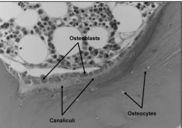
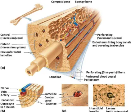
Throughout life, especially in response to physiological or mechanical changes, bones undergo modeling. This change is a gradual process to adapt to bodily changes and includes widening of bones and removal/addition of bone on the surface. As a stated by Wolff’s law, long bones accommodate stress by changing shape. Generally, formation of new bone is approximately a 4 – 6 month process. This is completed by osteoblasts synthesizing new organic collagen matrix and concentrating calcium and phosphate through membrane-bound vesicles. As part of the process, osteoblasts transition to osteocytes that become surrounded by a canalicular network.[1] When remodeling bone, osteoclasts use H+ -ATPase proton pumps to change the pH of the area by secreting hydrogen ions. This promotes bone mineral mobilization and enables the resorption of bone. In healthy bone tissue, bone formation is triggered by resorption. When the bone formation process is finished, 50 – 70% of osteoblasts experience apoptosis, as they are no longer needed. The remainder differentiates into either osteocytes or bone-lining cells.[1] Figure 2 illustrates new bone formation with osteoblasts synthesizing the collagen proteinaceous matrix to fill in resorption pits and the proteinaceous matrix progressively mineralizing into canaliculi to become new bone tissue. Canaliculi are long thin canals that connect lacunae (small hollow holes) to each other and the central Haversian canal (channel for blood vessels and nerves). Together these components make up osteons, the structural units of cortical bone.[2] Figure 3 shows the labeled components of cortical bone.
Figure 2. New bone formation through the transformation of collagen of the proteinaceous matrix mineralizing into canaliculi.[1]
Figure 3. Compact (cortical) bone components. (a) Segment of compact bone. (b) Close-up view of individual osteon segment. (c) SEM (left) and light microscope (right) cross-sectional views of
an osteon.[2]
B. Hydroxyapatite (HA)
Improving the life expectancy of skeletal implants by incorporating materials that encourage natural tissue regeneration, has stimulated much interest in the field of orthopedics.[3] Hydroxyapatite (HA) is considered to be one of the most osteoconductive materials[4], has excellent bioactivity, and biocompatibility[5, 6]. When implanted, it can induce the formation of a biocompatible layer of hydroxyl carbonate apatite (HCA) on its surface which enables bone tissue to migrate, resulting in a stable interfacial bond between the host tissue and the implant[7]. These factors permit its use in hard tissue surgery. Prior to the use of hydroxyapatite (HA) coatings, early reports indicate metallic femoral stems having aseptic loosening rates of 20 – 40% between 2 and 7 years after implantation. After 10 years rates of up to 30 – 40% were reported.[8] This created a demand for improving the adhesion of orthopedic metallic implants to host bone tissue.
Bone cements (PMMA, Cortoss), and coatings (calcium orthophosphates, CaP) were developed in an attempt to resolve this issue. Calcium orthophosphates (CaP) are a major class of coatings currently used to secure orthopedic implants. Calcium orthophosphates
are defined as containing calcium, phosphorus and oxygen. By definition, HA coatings fall into the category of CaP.[3]
Several studies have been performed suggesting that pores of HA coatings promote bone ingrowth, allowing for stronger fixation of orthopedic implants to bone.
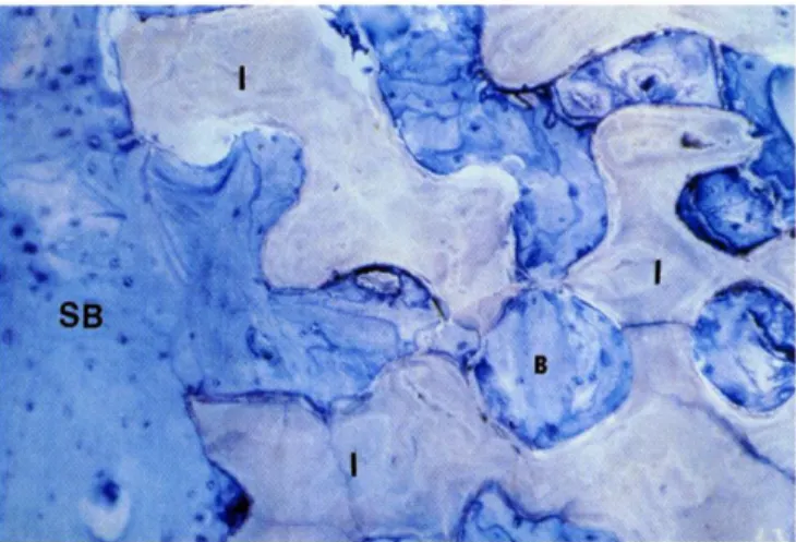
When testing maxilla bone ingrowth into blocks of synthetic HA (Interpore 200), the study reported significant ingrowth with all tested implants. Results indicate bone ingrowth slowing down and equilibrating approximately 20 months after implantation.[9]
Figure 4 taken 138 months after implantation illustrates total bone ingrowth of Interpore 200 HA block.
Figure 4. Image taken 138 months after implantation of (B) lamellar bone fully ingrown into HA pores of porous HA blocks (I) from (SB) surrounding bone tissue. [9]
1. Synthesizing Hydroxyapatite
Most calcium orthophosphates are somewhat soluble in water and are completely soluble in acid. Pure CaP has the characteristic of white colored crystals.[3] When forming CaP the Ca/P molar ratio, basicity, and solubility are all crucial features. All 3 parameters have a significant correlation with pH. Hydroxyapatite typically has a Ca/P molar ratio of 1.67 with a chemical formula of Ca10(PO4)6(OH)2. The stable pH range at 25°C for HA of this composition ranges from 9.5 to 12.[3]
For materials that deeply depend on their quantities of calcium and phosphorus, the Ca/P ratio is used to provide a simple relative composition of the material’s two main components. It is determined solely by dividing the total number of moles of calcium by
the total moles of phosphorus. The ideal ratio of 1.67 for synthetic HA is based on suitability for biointegration and also to synthesize the synthetic analogue as close to its natural form as possible, bone tissue. Some natural Ca/P ratios include: enamel = 1.63, dentine = 1.61, cementum ~ 1.65, and bone = 1.71.[3] In the case of the Ag and Cu-doped HA coatings, bone is the target natural material.
Hydroxyapatite is generally made by mixing a calcium, phosphate, and carbonate source. This typically involves mixing powders with acidic liquid. The reaction, often a precipitation reaction, causes a porous and interconnected structure, similar to the composition of bone, to form. The interconnected porous structure of HA encourages tissue, vascular, and bone ingrowth, as long as pores are larger than 70μm diameter.[10]
This can often be achieved by applying HA in layers. Typically, 3-5 coatings are enough to accomplish the desired structure and thickness.[11]
2. Biological Testing of HA (a) Animal Studies
After research and development of HA, extensive tensing was required to allow it to be initially released to the market and additional testing is required for any further modification of the material. One of the early studies of applying hydroxyapatite as a coating for metallic implants was in 1988 in which dogs were evaluated at 3, 5, 6, 10, and 32 weeks post implantation. In this study, HA was applied to Ti6Al4V implants and compared to uncoated Ti6Al4V implants. Results focused specifically on comparing mechanical properties. The HA-coated Ti alloy implants had a 5 - 7 times greater mean value for interface strength than the uncoated Ti alloy implants. After 10 weeks, this increased to an interface shear strength of 7.27MPa for the HA-coated implants verses 1.54MPa for the uncoated. After 32 weeks of implantation no significant HA resorption was noted.[8]
Another animal study evaluated HA-coated Ti screws implanted into cortical bone of ovariectomized sheep experiencing osteoporosis and healthy control sheep with significantly less bone degeneration. The largest factor of the study was the ovariectomy in which a much greater loss of trabecular and cortical bone was seen than in the control sheep. However, the HA-coated implants were still deemed superior to the uncoated due to significantly less bone degenerating than in the sheep treated with uncoated screws. It
was noted that there was a correlation of success of HA fixation with osteoconductivity and results suggest the use of HA when repairing cortical bone. A possible complication factor that was addressed by the study is the possibility of local infection after diaphyseal fractures.[12]
When comparing porous and solid hydroxyapatite samples in rat models, bone ingrowth was seen in the porous scaffolds; however, no bone ingrowth was exhibited in the solid HA. The same results occurred when comparing the porous HA-coated metallic implants to the same uncoated implants. When testing the porous HA coatings in canine total hip arthroplasty models, an average pore size of 350μm (45% porosity) was considered optimal.[13]
(b) Clinical Trials
After hydroxyapatite progressed to clinical trials, dental applications were common. A 6-year study included 65 patients totaling to 351 dental implants. There was a random distribution of HA-coated titanium plasma sprayed implants and control uncoated titanium plasma sprayed implants. Results dictate an overall success rate of 92.8% between the coated and uncoated implants, while defining loss of implant as a failure. When looking at the results of the first 15 implant failures, 12 were uncoated and 3 were HA-coated.[14]
In addition to dental applications, HA-coated implants are frequently seen in orthopedic cases throughout the body. Clinical trial research reports that metallic, particularly Ti, orthopedic implants coated with HA have had a 5-year success rate of 94.3%. It is also noted that there is greater and faster osseointegration of HA-coated than uncoated implants. Even though hydroxyapatite has seen notable success for tissue repair, especially bone, there is still significant room for improvement. There have been cases in which HA has detached from bone, meaning that when working to improve HA mechanical and adhesion properties must be highly considered.[15] A further consideration of calcium and phosphate materials such as hydroxyapatite, especially when used for bone repair, is the potential to introduce infection.[16]
C. Post Implant Infections
1. Infection Rates and Risks
Periprosthetic joint infection is a complication of joint revision surgeries such as total hip (THR) and total knee (TKR) replacement. These infections occur in approximately 1% of primary arthroplasties and 3-5% of revision surgeries. Joint infections can lead to the need for amputation or death if untreated. It is difficult to treat these infections because bacteria form an antibiotic resistant biofilm around the implant.
A common bacterium to cause this infection is Staphylococcus aureus.[17] Infection resulting from implants has been highly researched in animal models. Implant infection research using animal models was first published in 1975 with rabbit models. Canines started to be used in 1985 and then sheep became utilized due to their constant roaming, which models the movement of humans. In 2010 research transformed to mice. Strong evidence suggests that biofilms lead to infections.[17] In 2003 an estimated 200,000 total hip arthroplasties and 400,000 total knee arthroplasties occurred in the United States.
This is predicted to increase to 380,000 hip and over 1,500,000 knee replacements by 2020. Currently, post-surgical infection rates of orthopedic implants range from 0.3 - 8.8%. These infections are reported to be caused by surgical contamination of wounds, hematogenous spread, reoccurrence related to sepsis from a previously infected joint, or spread of infection from a preexisting source.[18]
2. Types of Infections
Post implant infections create a huge risk of chronic inflammation for the patient.
Killing bacteria associated with postoperative infections has always been an issue;
however, they are now even more of a concern due to the increasing antibiotic resistance of bacteria. Staphylococcus makes up approximately 2/3 of all pathogens involved in orthopedic implant infections. These strains of bacterium are also most common specifically in osteomyelitis and septic arthritis. Osteomyelitis is defined by a range of bone infections that are caused by microorganisms colonizing within bone tissue. This results in inflammation and destruction of bone. The joint disease septic arthritis occurs by bacterial colonization causing significant joint destruction over a short period of time.
This can even cause loss of use of the affected joint and is most common in hips and
knees. S. epidermis and S. aureus are among the most common Staphylococcus strains that are most likely to form biofilms around implant infections. They can be found in resistant forms on skin of patients, especially patients who are immunosuppressed. When this situation occurs, the risk of periprosthetic joint infection drastically increases.[19]
D. Methods for Fighting Infections with Hydroxyapatite 1. Antibiotic Integration
During manufacturing, after the application of HA coating, the implant is dried, packaged, and sterilized. Directly before implantation to avoid chance of contamination and to allow for optimal adhesion, the HA implant is removed from the package and is sometimes wetted. CaP can easily absorb liquid and the surgeon chooses the specific liquid, which includes options such as antibiotics or bone morophogenic protein.
Implants using CaP coatings typically have a large percentage of the surface coated, creating an ample location to apply a therapeutic agent such as an antibiotic or other antibacterial treatment. Some experimentation has been tried to enhance the antibacterial properties of hydroxyapatite. One method is using antibiotics in conjunction with other calcium and phosphate powders to incorporate antibiotics during synthesis. Filler is another possible addition to HA.[10]
2. Doping
The idea of ion substitution within hydroxyapatite is being evaluated for various applications. The idea of ion substitution within HA has been considered to improve the mechanical properties through the addition of Zirconia (Zr) [20, 21]Yttria (Y) [22] and bioactivity, (Strontium, Sr)[23], phase stability, and sinterability.[24] Naturally, apatite contains small levels of ions including: K+ Mg2+, Na+, CO32-, and F-. Some ion substitutions of HA are intended to more closely mimic the properties of the natural material such as bone that it will adhere to. When writing hydroxyapatite in the general formula A10(BO4)6(C)2 there are numerous elements and compounds that have been found to be an option for each A, B, and C.[24] Table 1 lists potential candidates that research indicates are possible for substitutions of A, B, and C.
Table I. Possible Ion Substitutions for HA.[24]
Some studies have been performed to analyze the effects of metal ions on hydroxyapatite properties. One study indicated that doping with Mg2+ increased grain size, while doping with Zn2+ decreased grain size. When sintering Al3+ doped HA at both 1100°C and 1300°C, the samples became thermodynamically unstable, thus resulting in transformation to TCP and CaO. It was reported that amounts >5 mol% of Al3+ in comparison to the mol% Ca2+ were more likely to cause this phase transformation.[24]
Doping HA by ion substitution continues to progress; however, a significant amount of future research must be performed in order to successfully predict results of doping HA with particular ions and specific concentrations.
At this point hydroxyapatite coatings containing silver (Ag) are most commonly made experimentally by replacing Ca ions with Ag ions by dipping HA into AgNO3. This works most effectively on the outer surface of the coating and has not been overly successful for the entire depth of HA coatings. For HA coatings, successfully being doped with Ag throughout the entirety of the coating, sol-gel, co-sputtering, and thermal or cold spraying methods have been used.[25] Synthesizing Ag-doped HA through a precipitation is a new concept and has shown promising results when synthesized at 100°C.[25]
Recently some experimentation has been conducted with copper (Cu) containing hydroxyapatite. HA has been doped with Cu in order to treat soil containing heavy meals.
Research has shown success in Cu-doped HA working to remove arsenic from water and soils.[26] In the past few years Cu-doped HA with copper being presented in the form of Cu (CH3COO)2⋅ H2O (copper acetate) has been synthesized to successful inhibit some bacterial growth; however, no success was seen when testing with S. aureus.[27]
Atom site Elements
A K+, Na+, Mn2+, Ni2+, Cu2+, Co2+, Sr2+, Ba2+, Pb2+, Cd2+,Y3+, La3+, Al3+, Fe2+, Zn2+, Mg2+, Ca2+, Ce3+
B As, P, Si, V, Cr C F, Cl, O, OH, Br
Evis and Webster Nanosize hydroxyapatite: doping with various ions
E. Antibacterial Metals 1. Silver
Silver (Ag) was first noted to have antibacterial properties in 1869 when the King of Prussia stored water in silver vessels. Aspergillus niger did not grow when water was kept in these vessels, thus keeping the water drinkable. A similar effect was noticed when using copper and tin as storage vessels. There were also early accounts of E. coli concentration being significantly decreased in water stored in silver. These early discoveries led scientists to continue to experiment with silver and its antibacterial properties. Ag+ has been found to bind to several different cellular components, especially membranes. When exposed to living cells, silver has a much lower toxicity to human cells than to bacteria.[28] Silver ions have two main methods of attacking bacteria and both combined have chance of increasing effectiveness of traditional antibiotics. The first method is making the cellular membrane of bacteria more permeable, thus allowing entrance of foreign material such as antibiotics or other bacterial toxins. The second method is altering the metabolism of bacteria to cause the release of toxic oxygen compounds.[29] Additionally, when Ag enters bacterial cells, internal cellular processes are shut down such as protein synthesis and DNA replication.[30] The antimicrobial mechanisms of silver are shown in Figure 5.
Figure 5. Antibacterial mechanism of Ag nanoparticles on bacteria.[41]
Studies indicate antibiotics used in conjunction with Ag+ ions in small concentrations increase effectiveness of killing bacteria by 10 – 1000 times. Vancomycin and Ag+ ions have shown promising results in killing bacteria that have protective outer coatings. Prior to this method of attack, it was very difficult to overcome the protective barrier of some strains of bacteria.[31] A clinical trial used 0.5% AgNO3 to prevent infections on severely burned patients. This significantly decreased infection and mortality rates. After various studies regarding introducing silver into the body, silver has not been found to be poisonous to mammals. One of the only noted negative effects is argyria, irreversible discoloration of skin or tissues, when used excessively. Several case studies indicate no cellular reactions to silver exposure.[28] Even though there is minimal evidence of silver being toxic to the human body, caution must be used to not use too high of a concentration of Ag+ ions when using internally. More recent studies indicate the potential of silver ions causing some tissue response, particularly the heart, when used excessively.[31]
2. Copper
Like silver, copper (Cu) as an antibacterial metal was also discovered very early on. Ancient Egyptian medical texts report Cu being used as sterilization for chest wounds and to keep water drinkable. The Greeks, Romans, and Aztecs also noted copper for medical applications. These include treating burns, intestinal worms, and ear infections.
The presence of copper has also been noted to unexpectedly treat sickness. Starting in 1832, there were multiple cholera outbreaks in Paris, France. Those who worked in the copper industry seemed to be immune to the disease. More recently research has shown that bacteria on copper surfaces experiences “contact killing.” Studies report a significant decrease in bacteria present after 6 - 7 hours of incubation and after prolonged bacterial exposure to a copper surface all microorganisms were killed. Copper has been so successful in killing microorganisms that it was the first solid antimicrobial material registered to the United States Environmental Protection Agency.[32]
MATERIALS AND METHODS
F. Hydroxyapatite (HA) Synthesis
HA powder, Cu-HA doped with 10mol% copper (Cu), and Ag-HA doped with 10mol% silver (Ag) were synthesized through precipitation at 25°C and a pH of above 10.0.[33] The control reagents were calculated to produce a molar Ca/P ratio of 1.67 and the doped samples had a molar (X+Ca)/P ratio, with X = doping element, of calculated to be 1.67.
78.77g (0.3335mol) Ca(NO3)24H20 was added to 600ml of deionized water and then made basic with 10ml NH4OH. 23.01g (0.2000mol) NH4H2PO4 was added to 1066ml of deionized water. Both solution beakers were heated to 25°C while undergoing vigorous stirring. After reaching 25°C, the temperature was maintained. pH of the Ca(NO3)24H20 solution was constantly monitored while the NH4H2PO4 solution was added drop-wise from a burette over 1 hour. During this hour the solution continued to be stirred vigorously. NH4OH was added frequently to the Ca(NO3)4H20 solution in correspondence with the pH which was sustained above 10.0. After the NH4H2PO4
solution finished dropping into the Ca(NO3)4H20 solution, the solution remained under the conditions of 25°C and vigorous stirring for another hour. Changes in temperature and pH of solutions were monitored using a Fisher Scientific Accumet XL15 pH meter.
Prior to testing, the pH meter was calibrated using pH buffer solution 4.00±0.02, 7.00±0.02, and 10.00±0.02 (Fisher Scientific, Pittsburgh, PA). The beaker was then removed from the heat and stirring, covered with Parafilm, and left for 24 hours at room temperature. The Parafilm was slotted to allow for evaporation. After 24 hours the supernatant was removed from the beaker, leaving the precipitate. The liquid was discarded and replaced with deionized water. After replacing the liquid, the precipitate was re-suspended by an hour of vigorous stirring at room temperature. It was then recovered with slotted Parafilm and left for 24 hours at room temperature. The removal of the supernatant, replacement of deionized water, and stirring was repeated twice, with the solution being left for 24 hours at room temperature only after the first repeat of the procedure. The removal of the supernatant purified the precipitate. Following the second repeat of the procedure, the suspension was distributed into 50ml centrifuge tubes. The
solution was centrifuged for 12 minutes at 3800rpm. The supernatant was then dumped and discarded from the centrifuge tubes. The precipitated HA remained in the bottom of the tubes and was scraped out with a spatula. The gel-like precipitate was then placed in ceramic crucibles and dried in a fan-assisted oven for 18 hours at 70°C. After drying, the HA was weighed and put in a Gy-Ro mill for 10 seconds in order to separate the agglomerated precipitate particles.
1. Doped HA Synthesis
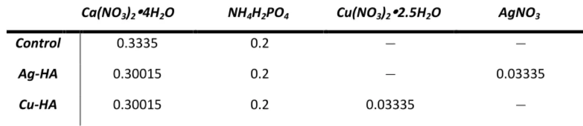
Both the Cu-doped and Ag-doped HA were synthesized using the same precipitation method as the pure HA. The one exception was the substitution of copper (Cu) and silver (Ag) for part of the calcium (Ca). The substitutions of copper and silver for calcium were done in an equal molar ratio. For the calculations of all synthesized HA mixtures, 0.3335mol Ca was considered to be pure HA with 100% of (X+Ca) being Ca.
For both 10mol% Cu and 10mol% Ag, 0.03335mol of the dopant was used in addition to 0.30015mol of the calcium source, allowing the (X+Ca)/P molar ratio to still equal 1.67.
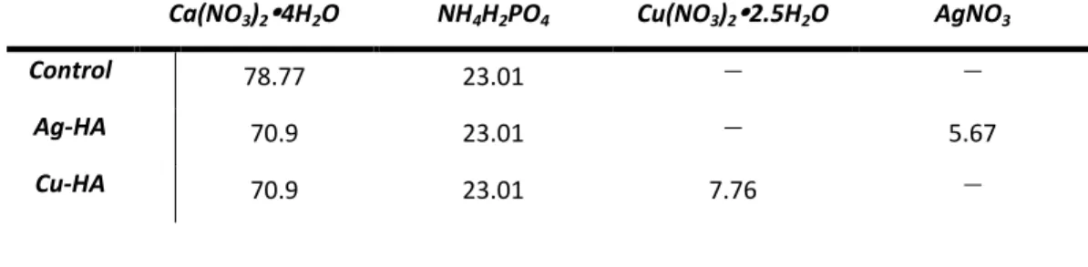
When converting moles to grams of reagents, the hydrate portion of the molecular formula was included. For each reagent, the total molecular weight was divided by the desired number of moles. Table 2 and Table 3 illustrate the total number of moles and grams respectively of each reagent used to synthesize each type of HA.
Table II. Moles of Reagents for Synthesis Reaction in 1066ml of Deionized Water
Ca(NO3)24H2O NH4H2PO4 Cu(NO3)22.5H2O AgNO3
Control 0.3335 0.2 − −
Ag-HA 0.30015 0.2 − 0.03335
Cu-HA 0.30015 0.2 0.03335 −
Table III. Grams of Reagents for Synthesis Reaction in 1066ml of Deionized Water
Ca(NO3)24H2O NH4H2PO4 Cu(NO3)22.5H2O AgNO3
Control 78.77 23.01 − −
Ag-HA 70.9 23.01 − 5.67
Cu-HA 70.9 23.01 7.76 −
(a) 10% Cu-doped HA
70.90g of Ca(NO3)24H20 and 7.76g Cu(NO3)22.5H20 were added to 600ml of deionized water and then made basic with 10ml NH4OH. The phosphate source remained the same as the pure HA. Both solutions underwent the same heating and stirring methods as the pure HA and the processing method remained the same throughout the entire synthesis.
(b) 10% Ag-doped HA
70.90g of Ca(NO3)24H20 and 5.67g AgNO3 were added to 600ml of deionized water and then made basic with 10ml NH4OH. Just as in the Cu doped HA, the phosphate source remained the same as the pure HA. Both solutions underwent the same heating and stirring methods as the pure HA and the processing method remained the same throughout the entire synthesis.
G. Sintering
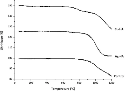
Hot Stage Microscopy (HSM) was used to determine a reference temperature for sintering each of the three HA compositions. A sample of HA powder of each composition was heated to 1200°C at a rate of 10°C/min by a Misura Heating Microscope and the data was analyzed by Misura Expert Systems Solutions 3.32 software. The temperature noted was when the sample was at 5% deformation. The pure HA was determined to start sintering at 967°C, Ag-HA at 936°C, and Cu-HA at 823°C.
Figure 6 illustrates the HSM data used to determine the sintering temperature for all disc compositions.
Figure 6. HSM data for HA, Ag-HA, and Cu-HA powders used to determine sintering temperatures of the discs.
Prior to sintering the powders in the form of discs, the powders were dried at 100°C and allowed to furnace cool. The dry powders where then hand ground with a mortar and pestle to breakup any agglomerations of powder. The discs were formed using a Carver Laboratory Press and a 4-ton die to compress 0.052g of powder for each disc. 3M Spray Silicone Lubricant was used to lubricate the die. In order to ensure all compositions were completely sintered, the three compositions were all held for 2 hours at 1100°C. The samples were placed in the furnace prior to heating and remained in the furnace until completely cool.
H. Characterization
1. X-ray Diffraction (XRD)
Prior to sintering, HA, Cu-HA, and Ag-HA powders were analyzed with powder diffraction under the measurement conditions of: 102 to 702, step size 0.022, and count time of 1 second. A Bruker D2 Phaser diffractometer was used to examine the specimen with Cu K radiation. Each powder sample was mounted as a back-loaded powder. DIFFRAC.SUITE EVA 4.0 with the 2014 database was used to perform
identification of the three powders in comparison to PDF cards. After sintering the discs, they were each examined with XRD using a zero-background sample holder and the same parameters as the powders. Changes in the all HA compositions after sintering were analyzed in DIFFRAC.SUITE EVA 4.0 with the 2014 database.
2. Particle Size: Dynamic Light Scattering (DLS)
Particle size of each of the synthesized HA powders was determined by using a Microtrac NanotracTM ULTRA DLS and Microtrac Flex 10.5.0 software. Prior to analysis, the powders were ground with a mortar and pestle to breakup powder agglomerations. A measurement was taken 3 times for each powder.
3. Surface Area: Brunauer-Emmet-Teller (BET)
Surface area was determined by using a Micrometrics TriStar II BET and TriStar II 3020 V1.04 software. Prior to measuring the powders, they were dried at 70°C for 24 hours and hand ground with a mortar and pestle. One sample of each of the 3 HA compositions was measured at a time in each of 3 ports, repeating the measurements a total of 3 times.
4. Surface Crystallization and pH: Simulated Body Fluid (SBF)
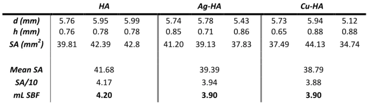
Sintered discs of each of the three HA compositions were placed in simulated body fluid and incubated at 37°C.[34] Three samples of each composition were tested for the time periods of 15, 30, and 45 days. The amount of SBF used with each disc was determined by calculating the average surface area of a sample of 3 random discs for each composition. The average surface areas were divided by 10 to convert the amount of SBF needed to milliliters. For the HA discs 4.20mL SBF was placed in each snap cap vial and for both Ag- and Cu-HA 3.90mL SBF was used. Table 4 shows the disc measurements and calculations for amount of SBF used per disc based on surface area.
To calculate surface area of the discs, only the surfaces in contact with SBF, the sides and the top of each disc, was included in the calculation. This was calculated with Equation 1.
SA = 2pi*(d/2)*h + pi*(d/2)2 Equation 1
(pi = 3.14159 d= diameter of disc h= thickness of disc)
Table IV. Measurements of Discs and Surface Area for Amount of SBF Required for Incubation
HA Ag-HA Cu-HA
d (mm) 5.76 5.95 5.99 5.74 5.78 5.43 5.73 5.94 5.12 h (mm) 0.76 0.78 0.78 0.85 0.71 0.86 0.65 0.88 0.88 SA (mm2) 39.81 42.39 42.8
6
41.20 39.13 37.83 37.49 44.13 34.74
Mean SA 41.68 39.39 38.79
SA/10 4.17 3.94 3.88
mL SBF 4.20 3.90 3.90
After each incubation period (15, 30, 45 days), 3 discs were taken out of the liquid and dried in an incubator for 24 hours at 37°C. The pH of the liquid was recorded using a Fisher Scientific Accumet XL15 pH meter. Prior to testing, the pH meter was calibrated using pH buffer solution 4.00±0.02, 7.00±0.02 and 10.00±0.02 (Fisher Scientific, Pittsburgh, PA). 500μl from each sample vial was stored in an a 1.5mL epindorph, placed under UV light for 24 hours, and stored in a -80°C freezer for future cell studies.
5. Ion Release: Inductive Coupled Plasma (ICP)
1 ml of SBF from each incubated sample was added to 9ml of deionized water for ICP. The ion release profile of each HA composition was measured using Inductively Coupled Plasma – Atomic Emission Spectroscopy (ICP – AES) on a Perkin-Elmer Optima 5300UV (Perkin Elmer, MA, USA). ICP – AES calibration standards for Ca, P, Cu, and Ag ions were prepared from a stock solution on a gravimetric basis. Three target calibration standards were prepared for each ion and de-ionized water was used as a control.
6. Scannning Electron Microscopy & Energy Dispersive X-ray Analysis (SEM/EDS)
An FEI Co. Quanta 200F Environmental Scanning Electron Microscope was used for imaging all powders and discs. Images of the powders were taken at a voltage of 15kV, spot size of 5.0, and using backscattered electrons. Additional compositional analysis was performed with an EDAX Genesis Energy-Dispersive Spectrometer (EDS).
EDS spectra were taken of control sintered discs and discs incubated in SBF for 15, 30, and 45 days. All EDS spectra were collected at 15kV. Quantitative EDS spectra were later converted into relative concentration data to determine the (X+Ca)/P ratio of each
powder. Prior to SEM imaging, all sintered discs were gold coated in order to reduce surface charging and enhance image quality. All images of the sintered discs were taken with both secondary and backscattered electrons at a voltage of 15kV and a spot size ranging from 3.0 to 5.0.
I. Bacterial Testing of Powders
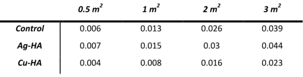
The antibacterial properties of the Ag and Cu-doped powders were tested in comparison to the pure HA powder with E. coli strain ATCC 8739 (LB agar and broth), and UAMS-1 S. aureus (TS agar and broth). Dry powders were hand ground with a mortar and pestle before being weighed and placed in a 24-well plate. The amount of powder in each well was calculated from the average surface area of each type of HA determined by BET. 0.5m2, 1.0m2, 2.0m2, and 3.0m2 of powder were used for each type of HA and tested in triplicate. The calculated amounts of powder in relation to surface area can be seen in Table 5.
Table V. Grams of Powder for Bacterial Studies Based on Surface Area Calculated by BET
0.5 m2 1 m2 2 m2 3 m2
Control 0.006 0.013 0.026 0.039
Ag-HA 0.007 0.015 0.03 0.044
Cu-HA 0.004 0.008 0.016 0.023
Prior to testing, each microbe was initially grown aerobically in liquid broth at 37°C for 24 hours and spread plated on agar plates with a sterile swab dipped in a 1/20 dilution of the appropriate 24-hour culture of bacteria. One colony of the appropriate 24- hour plated culture of bacteria was grown aerobically in liquid broth at 37°C for 24 hours. A 1/20 dilution of the bacteria was performed and 150μl of a 15ml tube of broth was replaced with 150μl of the 1/20 bacterial dilution. The total 15ml of bacterial/broth solution was divided between the 12 wells of powder and 3 empty wells. 3 additional wells were filled with 1ml each of pure broth. The plate was incubated for 24 hours at 37°C. After incubation, 100μl of broth was taken from each of the 18 filled wells in the 24-well plate and pipetted into a 96-well plate. This was repeated in triplicate.
To determine bacterial concentration of the broth, the 96-well plate was analyzed with a Bio-Tek μQuant plate reader and KCjunior software to measure absorbance with a wavelength of 490nm. The absorbance of the broth was subtracted out of each of the wells to determine relative concentration of bacterial viability off each sample compared to the control bacterial after the 24-hour period. For the Cu-HA powder, a control 24-well plate of each type of broth was made with the corresponding dry powders of concentrations 0.5m2, 1.0m2, 2.0m2, and 3.0m2 in order to account for the dying of the broth caused by the blue copper color.
The bacterial study was repeated at 1.0m2 and 2.0m2 for E. coli and S. aureus respectively at time intervals of 6, 12, 24, and 48 hours. For this study, the dying of the Cu-HA dry powder was measured at each time interval on both the TS and LB broth and subtracted out of the measured absorbance values. Liquid extracts from each time interval of the bacterial study were saved and stored in 1.5mL epindorphs in the refrigerator at 2°C to inhibit further bacterial growth and saved for future studies.
After removing the epindorphs of bacterial extract from the refrigerator, they were heated in an incubator at 37°C for 20 minutes. A sample from each epindorph was then made using 75L broth (LB for E. coli and TS for S. aureus), 50L deionized water, and 25L bacterial extract. The solutions were vortexed vigorously to ensure a homogeneity.
50L of each epindorph was plated on agar (LB for E. coli and TS for S. aureus). The plates were incubated for 24 hours at 37°C. A Synbiosis Protocol 3 colony counter was used to count bacterial colonies on each plate and image the plates.
RESULTS
A. Characterization of Powders 1. X-ray Diffraction
When matching the diffraction patterns of the synthesized pure HA and Ag-HA to PDF cards, both were identified as matches hydroxyapatite, Ca10(PO4)6(OH)2 and the empirical formula Ca5(PO4)3(OH). The diffraction pattern of the Cu-HA powder most closely resembled the PDF card of calcium copper oxide phosphate hydroxide, hydroxyapatite with the empirical chemical formula Ca5Cu0.1(PO4)3(OH)0.64. The diffraction patterns of the three powders are shown in Figure 7 and closest PDF Card match along with the identification are shown in Table 6.
Figure 7. Diffraction patterns of synthesized HA, Ag-HA, and Cu-HA powders.
Table VI. Identification and Associated PDF Card of Powder Diffraction Patterns
Diffraction Pattern Identification Associated PDF Card
Control HA Powder hydroxyapatite
Ca10(PO4)6(OH)2 00-064-0738
Ag-HA Powder hydroxyapatite
Ca10(PO4)6(OH)2 00-064-0738
Cu-HA Powder calcium copper oxide phosphate hydroxide hydroxyapatite
Ca5Cu0.1(PO4)3(OH)0.64 04-016-8198
2. Particle Size: Dynamic Light Scattering (DLS)
The mean particle diameter of each of the three powders all ranged on the order of 2,000nm with the standard deviations all on the order of hundreds of nanometers. The diameter is based on the MV measurement in which the volume distribution is used.
Table 7 reports the exact values for the mean particle diameter for each of three trials along with the standard deviations. The control powder had the largest mean diameter, followed by Ag-HA, and Cu-HA; however, the variation between the mean of the control and the mean of the Cu-HA powder was less than 200nm.
Table VII. DLS Particle Size (nm) Over 3 Trials with Standard Deviations
1 S.D. 1 2 S.D 2 3 S.D. 3 Mean
Control 2711 429.0 2810 497.0 2657 202.0 2726
Ag-HA 3220 625.0 3120 198.0 1603 122.9 2648
Cu-HA 3160 135.6 1919 64.90 2596 127.7 2558
3. Surface Area: Brunauer-Emmet-Teller (BET)
Similar to particle diameter, the calculated surface areas of the three powders all had similar results. The specific values for mean surface area of the powders as well as the standard deviation between trials is shown in Table 8. The Cu-HA had a higher calculated surface area in m2/g than both the control and the Ag-HA.
Table VIII. BET Surface Area (m2/g) Over 3 Trials
1 2 3 Mean S.D.
Control 102 64.65 65.39 77.35 21.35
Ag-HA 82.77 58.44 61.69 67.63 13.2
Cu-HA 162.97 115.26 106.22 128.15 30.49
4. Scannning Electron Microscopy & Energy Dispersive X-ray Analysis (SEM/EDS)
All three powders had the same C, O, Ca, and P peaks present in EDS analysis.
Additionally, both the Ag- and Cu-HA had small Ag and Cu peaks respectively. When imaging with SEM, it was evident that all three powders were of similar particle size and the powders agglomerate easily. Figure 8 illustrates the EDS spectra and SEM images of each powder.
Figure 8. EDS spectra and SEM images of HA, Ag-HA, and Cu-HA powders.
Quantitative EDS spectra resulted in (X+Ca)/P ratios of each powder being close to the ideal 1.67. The molar Ca/P ratio of the control HA was determined to be 1.63 while Ag- and Cu-HA had (X+Ca)/P ratios of 1.79 and 1.65 respectively. The composition of the powders determined by the spectra and the calculated (X+Ca)/P ratios are shown in Table 9.
Table IX. Composition of HA, Ag-HA, and Cu-HA Powders and Ca/P Ratios Determined by EDS
CaO P2O5 Ag2O CuO Ca/P
Control 76.52 23.48 − − 1.63
Ag-HA 77.6 21.9 0.5 − 1.79
Cu-HA 72.24 23.23 − 4.53 1.65
B. Characterization of Sintered Discs 1. X-ray Diffraction
Some change was seen in the diffraction patterns of the powders and the sintered discs. Both the pure HA and Ag-HA sintered discs were found to be biphasic, with some of the peaks matching with PDF cards of Ca3(PO4)2, known as tricalcium phosphate (TCP), and some peaks being identified as hydroxyapatite. There is an amorphous hump in the diffraction pattern of the Ag-HA sintered disc. The diffraction pattern of the Cu- HA sintered disc most closely resembled the PDF card of calcium copper phosphate with the chemical formula CuCa10(PO4)7. The diffraction patterns of the sintered discs are shown in Figure 9 and the closest PDF Card match along with the identification are shown in Table 10.
Figure 9. Diffraction patterns of HA, Ag-HA, and Cu-HA sintered discs.
Table X. Identification and Associated PDF Card of Sintered Disc Diffraction Patterns
Diffraction Pattern Identification Associated PDF Card
Control HA Sintered Disc hydroxyapatite Ca10(PO4)6(OH)2
tricalcium phosphate (TCP) Ca3(PO4)2
00-064-0738 04-010-4348 Ag-HA Sintered Disc hydroxyapatite
Ca10(PO4)6(OH)2
tricalcium phosphate (TCP) Ca3(PO4)2
00-064-0738 04-010-4348 Cu-HA Sintered Disc calcium copper phosphate
CuCa10(PO4)7 00-047-0899
2. Scannning Electron Microscopy & Energy Dispersive X-ray Analysis (SEM/EDS)
All sintered discs exhibited the same C, O, Ca, P, and Si peaks, with slight variations in peek intensity, present in EDS analysis. As seen in the EDS analysis of the powders, the Ag- and Cu-HA sintered discs had small Ag and Cu peaks respectively.
The EDS spectra of the discs incubated in SBF showed small peaks of elements present
in SBF (Mg, Cl, and Na). These peaks increased in intensity between the 15 and 45-day samples. The images of the control discs not in SBF indicate surface differences between each disc composition. Changes in surface structure are evident in all discs after incubation in SBF, with Cu-HA showing the most surface deposition. Surface cracking is evident by 45 days in SBF for the control HA disc, indicating that the disc experienced dehydration. Figure 10 depicts the SEM images of all disc compositions and time periods, while Figures 11 through 13 depict the EDS spectra over time of control HA, Ag-HA, and Cu-HA sintered discs respectively.
Figure 10. SEM images taken at 20,000x magnification of sintered discs after incubation in SBF.
(note: control HA image at 30 days was taken at 2,000x due to surface charging and inability to image at higher magnification).
Figure 11. EDS Spectra of HA sintered discs at 0, 15, 30, and 45 days incubation in SBF.
Figure 12. EDS Spectra of Ag-HA sintered discs at 0, 15, 30, and 45 days incubation in SBF.
Figure 13. EDS Spectra of Cu-HA sintered discs at 0, 15, 30, and 45 days incubation in SBF.
3. pH: Simulated Body Fluid (SBF)
An overall increase in pH was seen in the SBF liquid extracts of each disc over the 45-day incubation period. Both Ag-HA and Cu-HA discs caused increased pH of the fluid in the same trend and resulted in a mean pH of 7.98. This is slightly higher than the final mean pH of 7.90 of the extracts from the control discs. Overall, all disc compositions caused an increase in the original pH of SBF of 7.40. Figure 14 displays the pH changes of the SBF fluidextracts after 15, 30, and 45 days of discs in incubation.
Figure 14. pH changes of SBF extracts 15, 30, and 45 days of discs in incubation.
4. Ion Release: Inductivly Coupled Plasma (ICP)
Overall for all disc compositions, significant ion release was seen after incubation in SBF. Figure 15 illustrates the measured ion release seen of each element from ICP testing. Ca release increased relatively linearly for all three compositions over the 45-day period, with the highest concentration of Ca ions being released from Ag-HA and the lowest from the control after 45 days in SBF. P release decreased over the measured time period. The decrease was minimal for the Cu-HA disc and significant for both the control and Ag-HA. Both the Ag-HA and Cu-HA experienced increase with time of ion release of Ag and Cu respectively. In comparison to Ag-HA, Cu-HA experienced significantly more Cu release than Ag-HA did with Ag at all measured time intervals. By 45 days of incubation the mean ion release of Ag and Cu were 2.968 mg/L (SD 1.230) and 36.177 mg/L (SD 5.124) respectively.
Figure 15. Ion release of discs in SBF over 15, 30, and 45 days incubation a) calcium, b) phosphorous, c) silver, and d) copper.
C. Bacterial Testing of Powders
When testing the powders’ ability to inhibit bacterial growth in liquid broth, both Ag-HA and Cu-HA showed some resistance against both E. coli strain ATCC 8739 and UAMS-1 S. aureus. When testing growth of E. coli in broth over a 24-hour period with 0.5m2, 1.0m2, 2.0m2, and 3.0m2 of powder, some decreased bacterial growth was seen when exposed to Ag-HA and significant decreased growth was seen when exposed to Cu- HA when compared to both the control bacterial (no HA-powder exposure) and the control (pure HA) powder. The control HA had minimal effects on E. coli growth. 1.0m2 of both Ag- and Cu-HA showed the most bacterial inhibition of E. coli. When testing 1.0m2 of the powders during the time study (6, 12, 24, and 48 hours) bacterial inhibition
![Figure 1. Regions and components of a long bone. [1]](https://thumb-ap.123doks.com/thumbv2/123dok/10490021.0/10.918.259.708.233.567/figure-1-regions-components-long-bone-1.webp)
![Figure 5. Antibacterial mechanism of Ag nanoparticles on bacteria. [41]](https://thumb-ap.123doks.com/thumbv2/123dok/10490021.0/19.918.265.708.688.1011/figure-5-antibacterial-mechanism-ag-nanoparticles-bacteria-41.webp)