All the examples we present (except for a few real-life models at the beginning) will be drawn from scratch to demonstrate the more general and common modeling techniques mentioned above. The changes can then be applied to the model and displayed in the display area of the SAP2000 window. Use the drop-down list near the top of the form to select the table to edit.
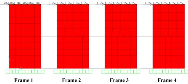
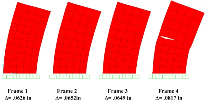
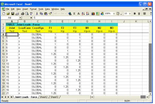
Equivalent joint loads are assigned to the 4 structures depending on the number of grid points along the vertices of the frames. Shown in Figure 1-3 below are the displacements of the upper right corner joint for each frame. This is why the deviation for Frame 4 is 33% greater than any of the other frames.
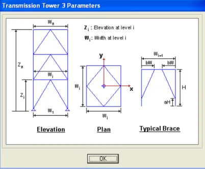
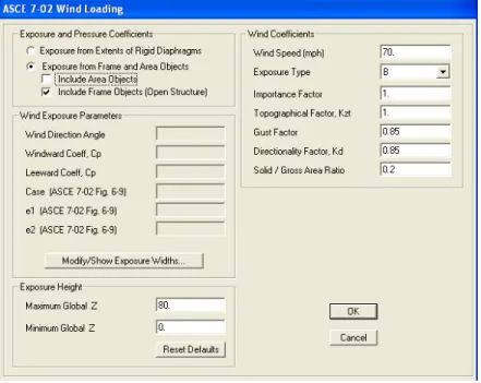
Leave all the default settings and select the parametric definition button to view the model parameters. For the wind coefficients, leave all the default values for this example (Wind Speed: 70 mph, Exposure Type: B). From the drop-down menu, select the wind load case and click the Open Structure Wind Loads option in the lower right corner of the screen.
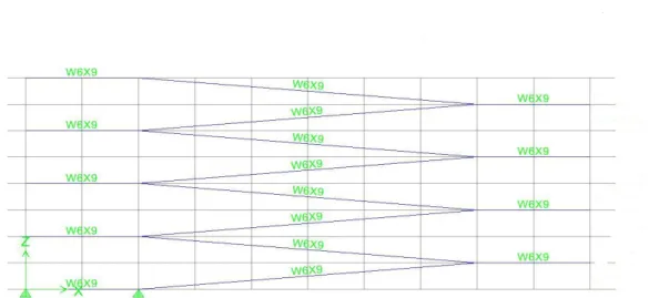
Loads will appear on all frame elements including columns and braces.
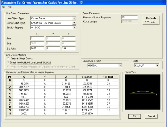
Curved Steel Truss Example
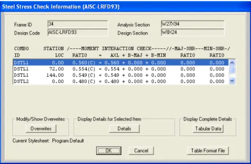
Auto-selection section lists are used in the design of steel frame, aluminum frame and cold-formed steel frame. Click the Design menu > Steel Frame Design > Set Lateral Displacement Targets command to open the Lateral Displacement Targets form, where you can specify displacement targets for different load cases. Design > Steel Frame Design > Start Design/Construction Check command starts the steel frame design process.
Therefore, the Design > Steel Frame Design > Start Design/Check of Structure command is not available if you do not run an analysis first. This command is not available if no frame elements are included with the Steel Frame design procedure in the model. Review some of the results of the steel frame design directly on the SAP2000 model (ie on the screen) using the Design menu > Steel Frame Design > Display Design Info.
Run at least one design using the menu Design > Steel Frame Design > Start. Select the Design menu > Steel Frame Design > Display Design Info command to access the Display Design Results form.
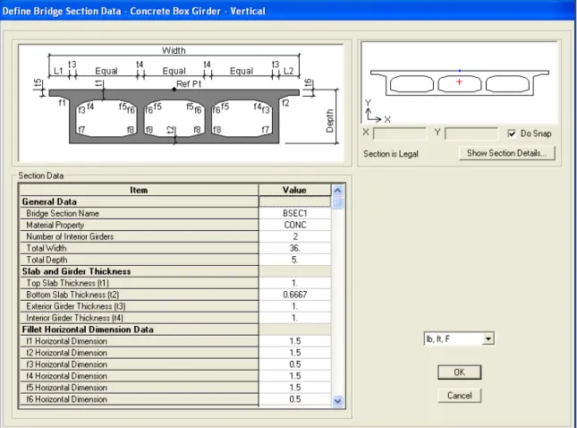
Concrete Box Girder Bridge Example
- Layout Lines
- Deck Section Definition
- Abutment Definition
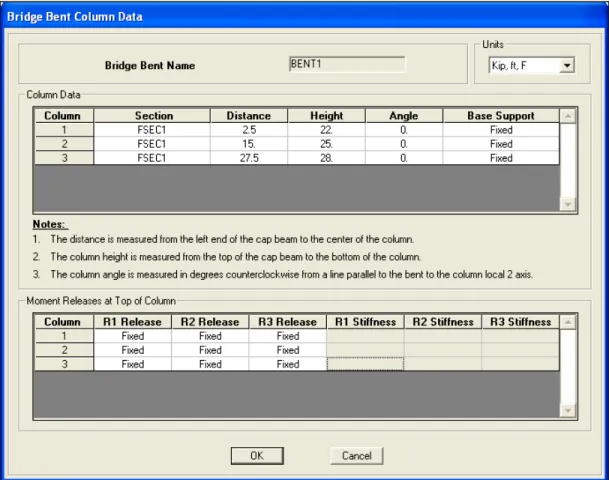
- Bent Definition
- Hinge Definition
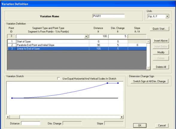
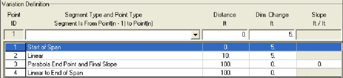
- Parametric Variation Definition
- Bridge Object Definition
- Update Linked Model
- Lane Definition
- Vehicle Definition
- Analysis Cases
Additionally, prestressed tendons can be added as part of the bridge object definition (see Step 8). After a deck section is defined, it can be assigned to a span as part of the bridge object definition (see Step 8). An abutment definition can be a specified link/support property or it can be a user-defined support condition.
A custom column support can be a specified Link/Support property or it can be a custom support condition. Once a bend is defined, it can be assigned to the bridge as part of the bridge object definition (see step 8). After a diaphragm definition has been created, it can be assigned to one or more spans in the bridge object (see step 8).
The hinge property can be a specified Link/Support property or it can be a user-defined resource. A constraint property can be a specified Link/Support property or it can be a user-defined constraint. A single hinge spring (and restraint) may be located at the reference line location, or multiple hinge springs (and restraint) may be located on each girder or spaced evenly across the width of the bridge.
Once a hinge definition has been created, it can be assigned to one or more spaces in the bridge object (see step 8). Any parameter used in the parametric definition of the deck section can be specified to change. Once a variation has been defined, it can be assigned to spaces in the bridge object (see step 8).
The update-related model command creates the SAP2000 object-based model from the bridge object definition. Spine models, area object models, and bridge solid object models can be created when the associated model is updated. The object-based model type created by the bridge object definition can be changed at any time.
Multi-step static and multi-step dynamic (direct integration time history) analysis cases can be used to analyze one or more vehicles moving across the bridge at any speed. To obtain shell tension forces on the bridge deck, go to Draw > Draw section Clip.
Eight Story Parking Garage Structure
Enter 36 ft. for dy and number of replications = 2 in the Increment Data field. Now reselect all the flat bars and the slanted bars that were not selected the first time. Draw developed height definition, type a name for the developed height in the edit box in the Developed Heights area of the form and click 'Add New Name'. Then click on the ramp edge joints in floor plan 8 until you have created a semi-circular developed elevation.
Now we are interested in creating a curved shear wall surface around the edge of the circular ramp surface which will run the full height of the structure. During compression, the cable/bracket will buckle out of the way in a more realistic representation of the true behavior. The linear property that you specify for each of the six degrees of freedom for a linear link element is an effective stiffness.
The linear properties that you specify for each of the six degrees of freedom of all connection element types except linear connection elements are an effective stiffness and effective damping. The output time step size is the time in seconds between each of the equally spaced output time steps. Use the File > Create Video > Time History Animation command to create videos in SAP2000 that show the motion of the structure during each time history analysis that is run.
The time increment controls how many different images (frames) of the deformed shape of the structure are created. For example, a time increment of 0.1 means that an image (frame) of the deformed shape is created every ten seconds of the time history. When applying the Finite Element Analysis Method, the most time-consuming task is usually the creation and modification of the system's finite element mesh.
The ETABS & SAP2000 object modeling environment clearly addresses these time-consuming drawbacks of the finite element method. In one case the mesh is uniform across the plate, and in the other case the mesh is fine on one half of the plate and coarse on the other half of the plate. In the latter case, an interpolation line constraint is automatically generated to ensure displacement compatibility between adjacent plate halves where the mesh does not match.
Displacement compatibility along the intersection lines of the ramp and the wall is automatically enforced by generating line constraints along those lines. As shown in the deformed shape of the Elevator Core, the wall mesh does not match the floor mesh in many places.