Some basic transient and analog modulation properties of the injection laser will be discussed in Chapter 3. The response of a laser diode to microwave current drive is studied theoretically by small-signal analysis of rate equations and experimentally using various lasers and standard microwave equipment. The rate equations predict the resonant peak of the relaxation oscillation in the frequency response of the laser. The absorber can be controlled by varying the pump current to the laser diode portion.

LASER KINETICS. RATE EQUATIONS AND mEIR RANGE OF APPLICABILITY
Significant simplification can be achieved if the spatial variable is integrated along the length of the laser. A more precise definition of the validity range is given below, using Moreno's approach[B]. A more precise definition of the scope of applicability of conditions (2.15). where the integrals are evaluated over the length of the laser.
TRANSIENT RESPONSE AND SMAIL SIGNAL MODUIATION CHARACTERISTICS OF SEMICONDUCTOR INJECTION LASERS
Comparision of transient responses of lasers with various structures
This type of laser has neither carrier nor optical confinement in the transverse direction (along the junction plane) and has a typical stripe width of 10 µm. This class of lasers, exemplified by the BH(Buried Heterostructure)[?] and the integrated laser[B], have both carrier isolation and optical directionality in the transverse direction. Except for those lasers that have built-in structures for limiting carriers in the lateral direction such as BH and embedded lasers, lateral carrier diffusion.

TJSY
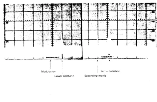
General behavior of self-pulsing lasers coupled to an external ca'rity
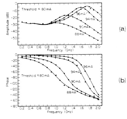
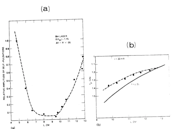
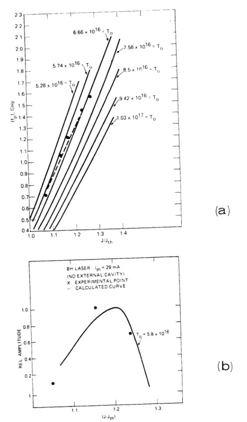
An analytical small-signal theory of laser-external cavity interaction, to be presented in the next chapter, will provide insight into how the pulsation behavior depends on the length of the external cavity, coupling coefficient, trap density, and parameters of others. The compactness of the fiber laser system makes it a very attractive method for stabilizing self-pulsing lasers in practice. A plot of pulse frequency and amplitude versus injection current is shown in Fig 4.l(a} and {b).
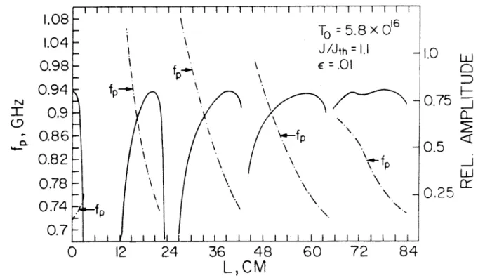
In Figure 4.4 we show the suppression of the self-pulsation using an external fiber resonator (EFR). The calculated amplitude and frequency of the self-pulsations are plotted against the length of the external cavity in Fig. The mechanism involved in the suppression of the self-pulsations is the locking action produced by the external cavity feedback.
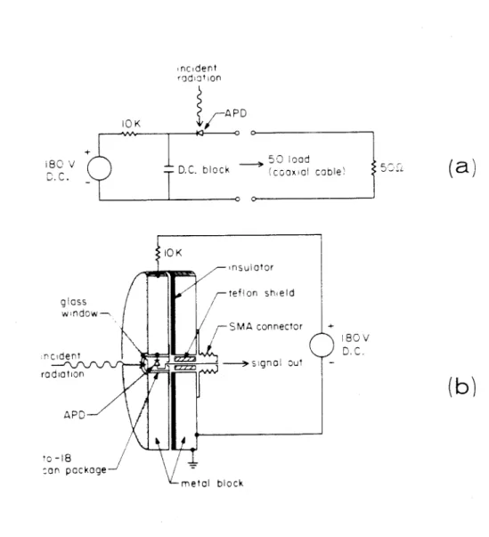
For very short cavity lengths (L < 3 cm}, the pulse width is comparable to the transit time of the light in the outer cavity and no frequency locking occurs. Light from the second side of the laser is focused into an APD and displayed in a spectrum analyzer or sampling oscilloscope Since the lens is an integral part of the external fiber resonator, alignment tolerances can be relaxed compared to a separate fiber and lens combination.
Since the laser output is polarized along the junction plane (TE), polarization conversion in the fiber effectively reduces the coupling efficiency.
Pasaive mode-lockin1 of injection laaera in an external cavity
The difference in pulse power in these three lasers can be attributed, according to the above theoretical model. The amplitude and frequency of the induced laser pulse in Fig. 4.12(c) are shown in Fig. 4.14; these results are very similar to the results shown in Fig 4.11. The effect of the external cavity is either to increase or suppress it, depending on the length of the cavity, as illustrated in Section 4.3.
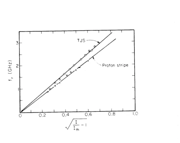
Using the equations from section 4.3 we can correlate the amplitude and bandwidth of the induced resonance with the length of the external cavity and the density of the absorber T0. Recently, Carney and Fonstad [41] fabricated an eight-section contact on a proton strip laser and, despite relatively high thresholds (>150 rnA), succeeded in achieving CW operation of the device. A possible explanation is due to the difference in the band gap of the two sections under different pumping conditions and the saturation.
To gain further insight into the dynamics of the laser-external cavity system, we will use a simple phenomenological saturable absorber in the following calculations. The effect of this additional term on the part of the locus closest to the origin is shown in Fig. As mentioned in section 4.5, such induced pulsation only occurs over a certain range of external cavity lengths.
As mentioned before, the dynamic behavior of the system is determined by the zeros off f.b. {s) {eqn. This is done in addition, resulting, for frequencies near the peak of the gain curve, in. where T is the external cavity round-trip time, and 19 is a small frequency drag term given by . We shall derive g {CJ) and the mode frequencies CJk's using the Nyquist plot - a plot from J.b. {s) in the complex plane.
NON-LINEAR DISTORTIONS IN THE MODULATION OF NON-SELF-PULSING AND WEAKLY SELF-PULSING INJECTION LASERS
Reduction of non-linear distortions by neaative feedback
First, there is a finite time delay between the onset of the current pulse and the switching on of the laser - the time required for the electrons to fill above the threshold level, as illustrated in fig. It just pushes the resonance frequency of the laser to a very high frequency by increasing the bias, and moduhtes in the small signal regime. The highest modulation bit rate achievable with the above scheme does not appear to be limited by the response of the laser diode itself.
The response of the laser can be made arbitrarily fast, provided the driving current pulse can be made. Calculated responses of the electron and photon densities to a short current pulse with a backward sweep. With the above parameters, the minimum pulse amplitude is approximately 30 times that of the cw threshold current.
This arrangement allows the laser to be driven by two consecutive current pulses of maximum available amplitude; the separation between the drive pulses can be varied by varying the relative phases of the RF drives to the SRDs. This bit rate was limited in our experiment by both the width and amplitude of the SRD drive current pulse and by the response of the APD detector. By using a shorter and more intense current pulse. a} The response of the laser to the drive pulse in fig. 7.6, corresponding to a 3.3 Gbit/sec modulation rate.
The real limitation of the transmission bit rate, then, is on the detector side of the link.
TRANSVERSE MODAL BAHAVIOR OF A
TRANSVERSE JUNCTION LASER EXCITED BY SHORT ELECTRICAL PULSES
Introduction
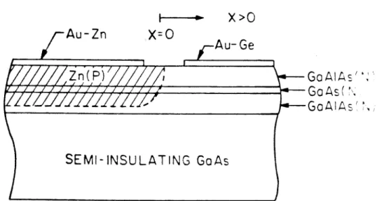
We will calculate the time evolution of the gain of the optical mode after the injection of an ion-intensive Narolf current pulse. The structure of the transverse mode of this optical pulse clearly depends on the amplitude and width of the carrier profile at the moment when the gain of the mode crosses (from below) the threshold. When using (8.3) as an initial condition, we assumed that the source impedance of the drive circuit is infinite, i.e.
However, from the equivalent circuit of a laser diode [6,12], it can be seen that the above assumption is valid for cases where the source impedance is large compared to the diode shunt resistance. The product of the width d and the amplitude A of the Gaussian gain profile is from equation {B.4}. The dependence of the position of the transverse mode on the amplitude of the pulse current predicted above was observed experimentally.
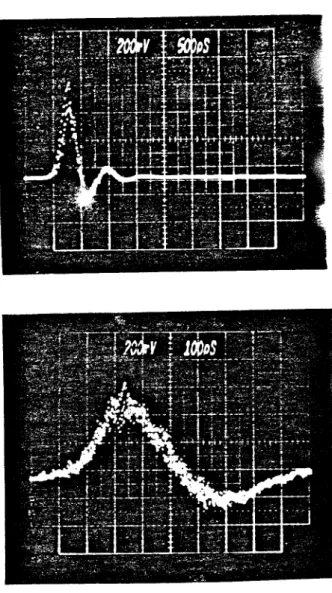
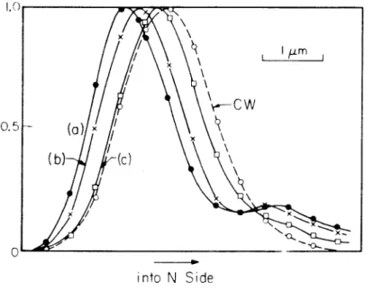
Plots of mode gain versus (a) time after a current pulse is injected and (b) width of the diffuse hole profile on the N side of the junction. for different pump current amplitudes. p1th is the minimum mode gain for lasing when no de is applied. The laser responds to the current pulse with a single sharp optical pulse whose width is very likely below 100 ps - the rise time of the APD used. As the peak current of the exciting pulse increases, the mode shifts closer to the junction.
The mode structure of the cw-driven laser, unlike what is expected from a gain-guided mode, does not shift significantly with bias current.
APO+
SCOPE
This does not happen with short-pulse excitation, because when the photons become depleted, the optical pulse is already over. At a certain fixed level of bias, the pump current pulse must exceed a certain amplitude before an optical pulse is generated. As the amplitude of the current pulse increases, the delay quickly shortens and becomes imperceptible.
Delays smaller than 100 ps, as shown in the figure, cannot possibly be detected by an APD with a rise time of 100 ps. Moreover, the delay difference for different pump pulse amplitudes can be even smaller than that shown in Fig. On the other hand, the position of the transverse mode shows a much larger variation than the time delay.
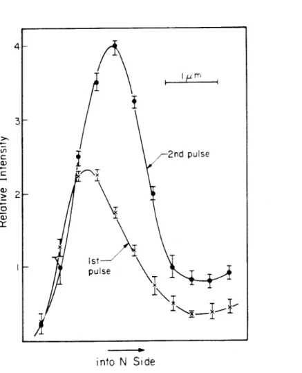
This dependence of the transverse mode structure on the pump is strongly demonstrated when the TJS laser is pulsed by two closely spaced electrical pulses of different amplitudes. The impedance of the laser presents a large mismatch with the 500 line and as a result there is a reflected electrical pulse of approximately ~ amplitude of the original pulse and opposite polarity that propagates from the TJS back to the SRD. The separation between these two pump pulses in our experiments is about 1.3 ns, which is comparable to the spontaneous lifetime of the carriers.
Although the second electrical pulse is weaker than the first, the second optical pulse can be equal to or even greater than the first due to the residual charge - the pattern effect, as shown in Figure 1.
This regime is characterized by a rapid increase in output optical power and a narrowing of the emission spectrum. This increase in modulation speed was attributed to a shortening of the carrier lifetime due to stimulated photon emission. This chapter presents the results of numerical calculations of the frequency response of small signal modulation.
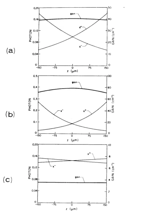
These conditions require that the reflectivity of the mirrors be less than 10-4, and that the spontaneous emission factor be less than 10-3. To investigate the modulation frequency response of the superluminescent diode, we use the usual perturbation expansion. a) Static photon output of, and (b) gain and photon distributions in a superluminescent diode. The solution is given by an appropriate linear combination of the above two solutions, such that x-(L /2) = 0.
In the case of superluminescent diodes, the spontaneous emission has a strong effect on both the damping as well as the magnitude of the resonance. However, one interesting feature of the frequency response of superluminescent diodes is that the corner frequency is invariant with gL, total unsaturated gain of the device. The following calculations are performed to illustrate the effects of a small but finite mirror reflectivity on the frequency response of the superluminescent diode.
It also serves to illustrate the actual range of validity of the conventional rate equations.